MagniSight Journey MSJ-17 User manual

MSJ-17 User's Manual

Table of Contents
SECTION 1: Unpacking and Set-Up of System...................................2
SECTION 2: Features and Operating Instructions..............................4
Turning ON the System.................................................................4
Selecting Viewing Mode................................................................4
Adjusting Magnification................................................................6
Adjusting Brightness....................................................................7
Adjusting LED Lights....................................................................7
Using the Viewing Table...............................................................8
SECTION 3: Service and Safety Information......................................9
FCC Information:
This equipment has been tested and found to comply with the limits for a Class B digital
device, pursuant to part 15 of the FCC Rules. These limits are designed to provide
reasonable protection against harmful interference when the equipment is operated in its
installation. This equipment generates, uses, and can radiate radio frequency energy
and, if not installed and used in accordance with the instruction manual, may cause
harmful interference to radio communications. If this equipment does cause harmful
interference, the user will be required to correct the interference.
1

Section 1: Unpacking & Set-Up
1. Remove User’s Manual and power adapter from top foam
compartments.
2. Next, pull UP on the rear portion of the foam, and then remove foam
packing sleeve by sliding it off of the LCD Monitor.
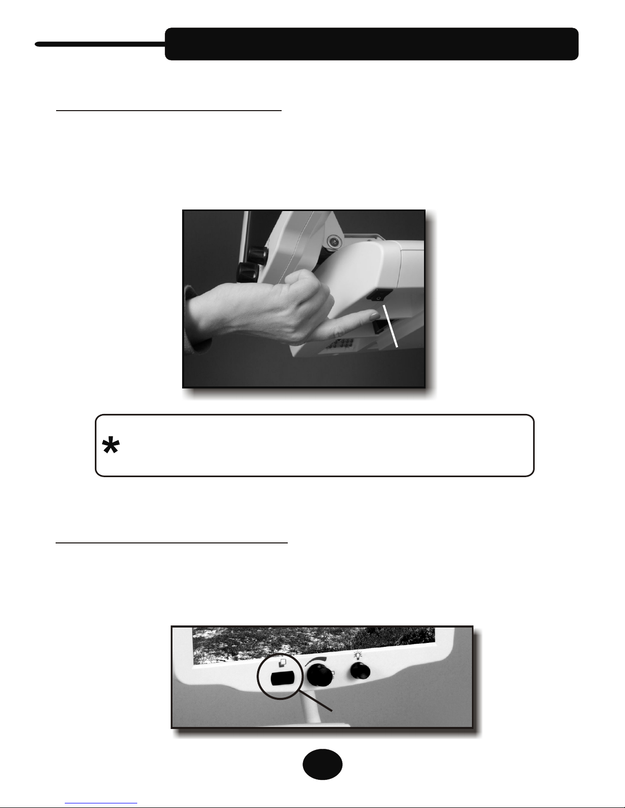
3. Gently tilt LCD monitor back to its original position. Reach below
sides of LCD monitor and firmly grab hold of each side of camera
unit and l (
ift unit out of foam packing in bottom of the carton DO
NOT pull up on LCD monitor).
IMPORTANT: DO NOT DISCARD packing carton and materials.
These should be kept in the event service or return of the
unit is required.
!
2
4. Place Unit on sturdy desk, table or
stand where it will be used. Avoid
places near any heat source or
direct sunlight. Using hand holds
on either side of the base platform,
position unit on desk surface to
your preferred location. The
bottom of the unit is equipped with
rubber pads to protect the table
surface and to prevent the unit
from sliding.
5. Next, connect the power adapter to the
camera unit by inserting the DC power
plug (small metal tip) into the Power
Jack on the rear of the camera unit.
Plug one end of the AC power cord
securely into the power adapter and
the other end into a surge-protected
power strip (recommended) or a
standard wall outlet.
Power Jack

6. Tilt LCD Monitor to a vertical position. Adjust Monitor to desired
height by gripping both sides of the LCD monitor and sliding it up
or down on its adjustable track in a smooth, even motion. After
turning the Journey ON, re-check the height position for most
comfortable viewing. The screen can also be tilted forward or
backward to angle the screen for best user comfort.
3
Set-Up (cont’d)
Up
Down
Tilt
F the system
should be at normal room temperature b
or best performance and optimal image quality,
efore turning the
system ON (see Page 4).

Section 2: Features & Instructions
Turning ON the System
Selecting Viewing Mode
Turn the unit ON using the Power Switch located on the front, right
corner of the camera housing. The LED Lighting should illuminate the
Viewing Table, and the screen should automatically come on after a
normal delay of a few seconds.
If the LED Lights do not illuminate and the screen does
not come on, please check the power adapter connections
described in the previous section.
4
Located on the panel below the Monitor Screen, the Mode Switch allows
a choice of Full Color and selected black & white or color combinations
for optimal viewing, based on your unique vision needs.
Mode Switch
Power
Switch

1. Full Color Mode (the factory default)
2. Enhanced Reverse Mode (white text on black background)
3. Enhanced B&W Mode (black text on white background)
4. Yellow/Blue Mode (yellow text on a blue background)
5. Yellow/Black Mode (yellow text on a black background)
6. Custom Color Mode (an optional feature)
Once chosen, the setting will remain permanent until you make a
different choice.
By pushing the Mode Switch to the RIGHT or to the LEFT you cycle
forward or backwards through the following viewing modes:
The Custom Color Mode allows you to choose various foreground and
background color combinations for optimal viewing, based on your
vision needs. When switched to this Mode, "Custom Color" is briefly
displayed on the screen.
To select Custom Colors, reach around the left side of the unit to the
LEFT REAR corner of the camera unit’s Rear Panel to locate the
Custom Color Rocker Switch (it is located next to the Power Jack).
Note: While in any Mode, you can return to the default Full-Color
mode by pressing and holding the Mode Switch to the LEFT for
2 seconds
Selecting Viewing Mode (cont’d)
Rock switch to the OUTSIDE (left) to change the FOREGROUND
COLOR
Rock switch to the INSIDE (right) to change the BACKGROUND
COLOR
5

Magnification, or SIZE of the image being viewed, is adjusted by
turning the Size Control (large middle knob below the screen).
Turn RIGHT to make image LARGER
Turn LEFT to make image SMALLER
The size setting is retained when turning OFF the unit and will start
with that setting when you power ON the machine.
Magnification can also be adjusted by using the programmable SIZE
PRESET feature. This feature allows you to save your favorite SIZE
setting in the camera. A default Size Preset is programmed by the
factory. It is activated by pushing IN on the Size Control (”Preset ON”
is briefly displayed on the screen).
To program your own preferred Size Preset level, first turn the
Size Control to the desired magnification level. Next, PUSH AND
HOLD IN on the Size Control until “Preset Saved” appears on the
screen (approx. 4 SECONDS).
Confirm your Size Preset is saved by turning the Size Control to
a different setting (as soon as you adjust the Size Control, the
camera will reset to manual Size adjustment and “Preset Off”
appears on screen). Now press IN once on the Size Control and
the size should adjust to your saved setting.
Adjusting Magnification
When first learning to use the camera system, place printed
material on the Viewing Table and adjust the Size Control to
the smallest magnification setting. Then begin turning the
Size Control to increase the size of the image until you are
able to read the text.
6
Size Control

Adjusting Brightness
Adjusting LED Lights
The Brightness Control is used to BRIGHTEN or DARKEN the image
being viewed. Brightness can be readjusted whenever needed, in any
mode.
Turn LEFT to Darken image
Turn RIGHT to Brighten
Brightness Control
The long-lasting LED Lights provide a warm white, non-glaring light.
The factory setting allows for the most light and best image
(decreasing the light intensity causes loss of color and reduced image
quality)
If the light is too bright, place your
hand on the underside of the camera
unit and slide you fingers straight
back from the Power Switch unit
until you feel a set of bumps behind
the back-right corner of the lens
opening. Between the two raised
bumps there is an adjustable knurled
dial.
UNCLICK and roll dial backwards to dim light intensity
Click dial forward to return to full intensity (the factory
recommended preset)
7

Using the Viewing Table
The Viewing Table (sometimes referred to an X-Y Table) is mounted on
a slide mechanism allowing it to move under the camera left to right
and also front to back. This assists you in moving the material you are
viewing under the camera.
Depending on what is being viewed, sometimes users prefer that the
Viewing Table remain steady or locked. The Table is equipped with a
Brake Lever to slow down or Lock the movement of the table. The
Lever is located below the front edge of the table as shown.
Pushing the lever all the way to the RIGHT locks the table
Releasing the lever all the way to the LEFT restores full table
movement front to back and side-to-side
Additional Table Features Include:
1. Rear Alignment Edge on the table allows you to line up pages or
envelopes. This is especially useful for writing.
2. Non-glare wipeable table surface reduces eyestrain. Its dark color
and speckled pattern helps you to distinguish the edge of a white page.
3. The indentations at the front of the Viewing Table can be used for
small pens or pencils or as finger grips.
Brake Lever
8

Section 3: Safety & Service
Safety Information and Maintenance
1. ALWAYS put the Viewing Table in the LOCKED position (Brake Lever
to the far right) and use the hand holds in the base of the unit when
attempting to move the machine.
2. Place unit on a sturdy table away from any heat source. DO NOT
place your unit on an unstable table, cart, or stand. Doing so may allow
the unit to fall causing serious damage to the unit or bodily injury.
3. Use of a surge protected power strip is recommended to protect
your unit from power outages, etc.
4. Avoid putting your hands and fingers into any opening (touching the
camera lens or mirror in the camera housing could reduce image
quality).
5. Dust the screen as needed with a soft, dry cloth.
6. Making sure that the unit is powered OFF, use a slightly damp cloth
to clean the unit’s plastic surfaces. Avoid using harsh chemicals or
cleaning liquids on the unit.
Service Information
Your Unit CONTAINS NO USER SERVICEABLE PARTS. ALL SERVICE
MUST BE DONE BY AN AUTHORIZED SERVICE CENTER.
In the event of malfunctions or questions, please contact us:
MagniSight, Inc.
3631 North Stone Ave.
Colorado Springs, CO 80907
Call (719) 578-8893
or (800) 753-4767
9

Removing the Camera Head
1. Before attempting to remove the Head Unit, raise the screen on its
track to the highest vertical position and then tilt it all the way back
over the camera unit (as shown). Hold the monitor by the outside
edges of its frame as you tilt it to avoid pinching your fingers.
2. While gripping the camera FIRMLY, push in the RELEASE buttons
that hold the sides of the camera unit on the supports arms.
CAUTION: As soon as you pull forward slightly on the head unit it will
release completely from the support arms.
3. To replace the Head Unit, carefully guide it onto the support arms
and push back until it SNAPS SECURELY onto the Frame arms. Be
careful not to pinch your fingers when replacing the Head Unit.
NOTES:
Service Information (cont’d)
In the event Service is required, you may be asked to send all or part of
the unit. The camera head (camera housing and monitor) can be
removed from the Frame and Viewing Table base for portability or for
service.
10
Push IN
Table of contents
Other MagniSight Magnifier manuals

MagniSight
MagniSight EXPLORER Classic MSE-L19 User manual

MagniSight
MagniSight MSE-L24-HD Explorer HD User manual

MagniSight
MagniSight MSE-L22 Explorer Classic User manual

MagniSight
MagniSight Explorer MSE-L22-HD User manual

MagniSight
MagniSight Explorer MSE-L19-HD User manual

MagniSight
MagniSight MSE-AC17-VS User manual