jbc RM User manual

RM
REWORK STATION
www.jbctools.com

2
RM / REWORK STATION
JTE-2A/1A/9A
CONTROL UNIT
DD-2B/1B/9B
CONTROL UNIT
MS-A
DESOLDERING PUMP
JT-SA
STAND
AD-SC
STAND
CL9885
TIPS CLEANING STAND
DR-SC
STAND
T245-A
HANDPIECE
DR560-A
DESOLDERING
IRON
T260-A
SUCTION
HANDPIECE
C245903
C245006
C560013
C560004
C560005

3
JT-T2A (230V) or
JT-T1A (100V-120V)
HEATING SET
0008752
EXTRACTOR STAND
Protector
P2220 (32)
P2230 (48)
P2235 (24)
P4000 (44)
P4010 (60)
Extractor
E2184
E2084
E2068
E2064
E2052
JN2015 ø4
JN2012 ø6
JN2020 ø8
NOZZLE
0930110
SUCTION CUPS
0932330
SUCTION TUBE
T2050 ø20
T2250 ø40
TRIPOD
0812360
0780840
0786640
0812630
0812620
0965760 0965970 0780550
0901546
STRAIGHT NEEDLES
0861660
BENT NEEDLES
0940163
CUPS
S0354
SPONGE

4
CORD X2 MANUAL MANUALMANUAL MANUAL
0780637
CONNECTION CABLE
0821830
SUCTION FILTER SET
0005966
50 FILTERS BOX
0781046
SPARE COTTON FILTERS
JBC stations intelligently manage the tool temperature:
Work mode: When the tool is used, pre-set work temperature is 350º C.
Sleep mode: When the tool is in the stand, the temperature goes down to 180º C
(depending of the configuration).
Hibernation mode: After longer periods of inactivity (pre-set i.e 30 minutes), the power is cut off and the
tool cools down to room temperature.
Heat management increase tip life which reduces cost of ownership.
HEAT MANAGEMENT
RM
REWORK STATION
www.j b c to o ls . co m

5
DD-2B
CONTROL
UNIT
JTE-2A
CONTROL
UNIT
MS-A
DESOLDERING
PUMP
0964551
Pedal (Optional)
Power cord
switch
Power cord
switch
Equipotential
connection
Equipotential
connection
DR-SC
STAND
AD-SC
STAND
DR560-A
DESOLDERING IRON
T245-A
HANDPIECE
Heating
element
Suction
Tube
Friendly
display
control
INSTALLATION & PART NAMES

6
0005966
Spare filter
0781046
Spare filter
0821830
External filter
0004710
Filter cover
0007717
O Ring
Control unit “switch on” indicator
Pump use indicator Desoldering air filter
MS ELECTRIC DESOLDERING PUMP ELEMENTS
CHANGING PUMP FILTERS

7
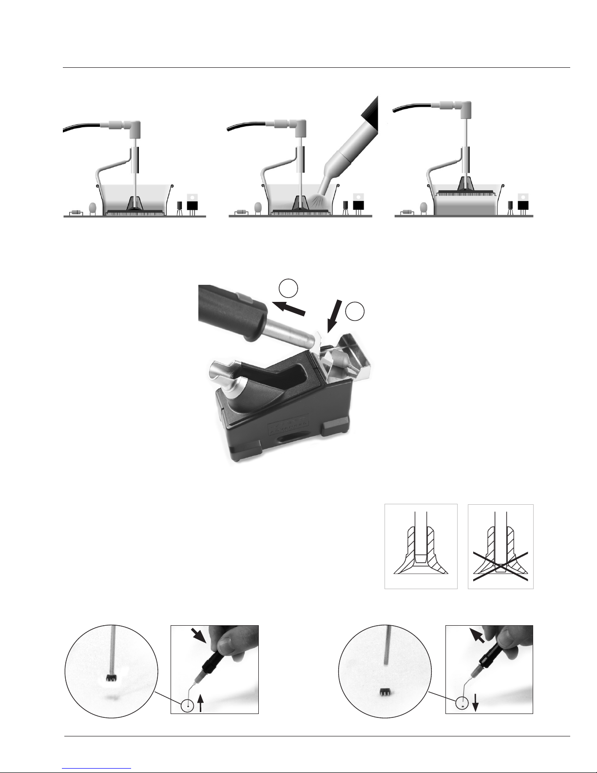
FOLLOW THIS PROCESS INVERTED TO RE-CONNECT THE HEATING ELEMENT
This step has to be performed when the tool is stopped and the heating set is cold.
1. Untighten screw.
2. Separate the heating element from the heating set’s handle.
3. Connect the new heating element, pushing it’s extreme.
4. Insert screw to avoid air-loss which could reduce the heating element’s lifetime.
0011070 (230V) or
0007565 (100V-120V)
Heating element
0009829
Handle
JT-T2A (230V) or
JT-T1A (100V-120V)
Heating set
REPLACING THE HEATING ELEMENT
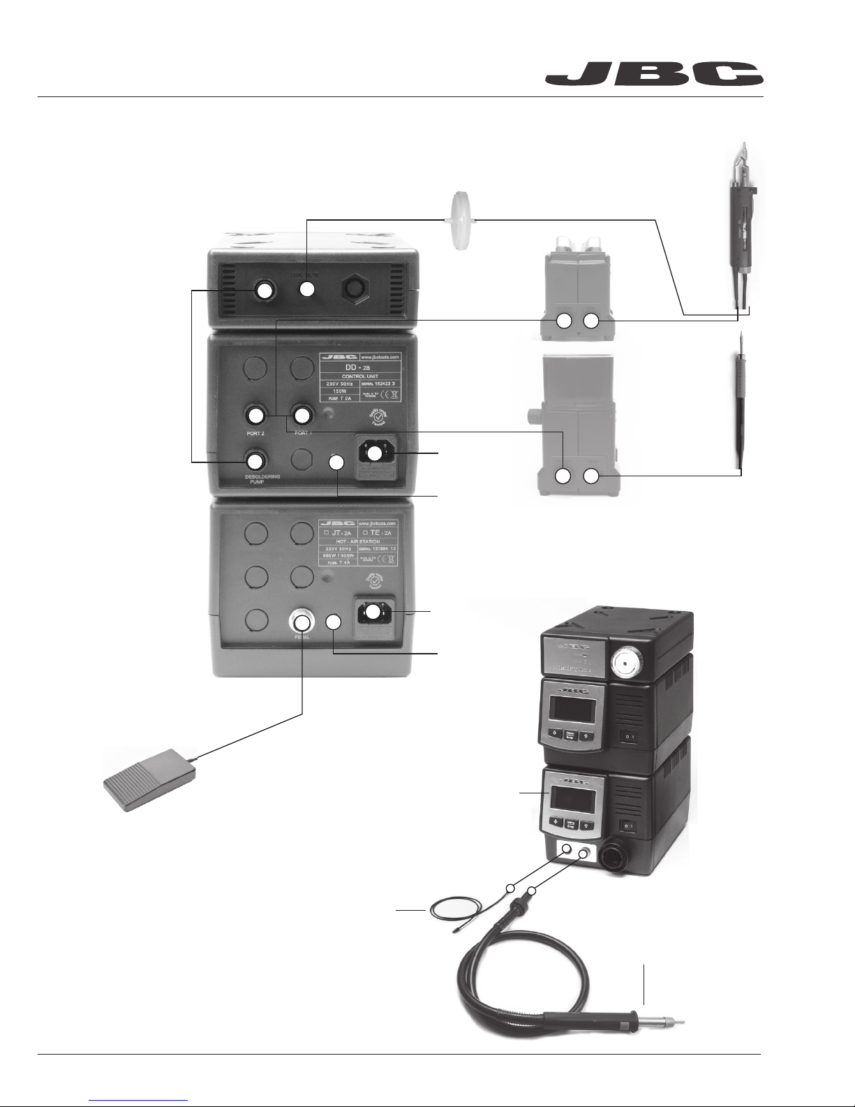
CHANGING THE HEATING SET
1. Ensure that the tool is stopped
2. Use a wrench to unscrew the cover
3. Pull back the seal
4. Pull connector from the socket to disconnect
the heating set from the station
5. Follow steps in reverse
to connect the heating set

8
1. Lock the extractor 2. Hot-air melts the solder 3. IC is removed automatically
The suction cups can be adjusted to the needles in order
to make the placement of SMD of different sizes on boards easier.
These accessories allows the adjustment to weight and size
of any type of component.
When you assemble the suction cup with the needle,
you should avoid the needle to stick out of the lower part.
HOT AIR DESOLDERING PROCEDURE
REMOVING THE NOZZLES
T260 PICK & PLACE
2
1

9
CL6205 INOX WOOL CL6220 BRUSHES TT-A TIP TINNER-CLEANER
CL6210
BRASS WOOL
S0354 SPONGE
CL0236 WIPER
Wiper can be easily removed to clean it.
TAPPING WIPPING
CL6220 Brushes
CL0354 Sponge
CL6210 Brass wool
CL6205 Inox wool
CL9885 TIP CLEANING STAND
CL0236 TIP WIPER
OPTIONAL

10
Main menu
Counters
Tool settings
Exit
1 Reset settings
2
Station settings
3
Tool settings
1
Plugged hours 0
2
Working hours 0
3
Sleep hours 0
1
Fix one temp -----
2
Temp levels set OFF
3
Sleep delay 0 min
4 Counters
5
Program version
4
Hibernation hours 0
5
No tool hours 0
6 Sleep cycles
0
7 Desold cycles
0
4
Sleep temp 180
0
C
5
Hibernation delay
3
0 min
6
Temp adjust O
O
C
Tool DR
Port 1 Port 1/2
Port 1/2
Tool DR
Port 1
Back
Back
0
c
Selected temp.
350
o
C
Power 10%
350
Decrease & move down Increase & move up
Tip temperature
% Instant power supplied to the tool
ORIGINAL PIN: 0105
Station settings
1 Temp unit
Celsius
2
Maximum temp 400
0
C
3
Minimum temp 200
0
C
4
Nitrogen mode OFF
5
Help text OFF
6 Beep ON
7 Power limit 150W
8
Change PIN
Back
Access Menu &
Confirm Selection
DD CONTROL SCREEN
SETTINGS MENU

11
ORIGINAL PIN: 0105
JT CONTROL SCREEN
MANUAL MODE
PROFILE MODE
SETTINGS MENU
Decrease &
move down
Decrease
profile number
Increase &
move up
Increase
profile number
Access Menu &
Confirm Selection
Access Menu
(pess key 2 seconds)
Temp
º
C Temp
º
C
Air %
º
C
Time to stop 45 seconds
Profile 8
Power 70%
400 380
80
Selected temperature
Current
temp.
% Instant power supplied to heater
Selected profile Current temperature
Selected flow
Graph of
selected
profile
Remining time
400ºC Select Air 100%
Time 125s.
You can switch between operating modes (Manual Mode / Profiles Mode) by pressing the “increase”
and “decrease” keys simultaneously for 2 seconds. (Only if mode profiles is ON)
Select
Profile
Step 4
Time 20
Temp 450
Air 100
º
C
º
C
Edit Profile
Edit Profile 8
8
Main menu
Settings
Counters
1 Reset settings
2 Station
Settings
3
Profile Settings
4
Counters
5 Program version
1
Temp unit Celsius
2 Maximum
temp 450
0
C
3 Minimum temp T OFF
4 Fix temp 400
0
C
5 Max air 100%
6 Min air 10%
7 Fix air 40%
8 Time to stop 120 sec
9 Beep ON
10 Pop up ON
11 Change PIN
1 Station ON hoursrs
0
2
Works hours 0
3 Works
cycles 0
Exit
Back
Back
Exit
*
* Selecting Tmin to “T OFF” allows
for blowing at ambient temperature.
Profile settings
1 Profiles
2 Edit Profile
3
Copy profile
Exit

WARRANTY
JBC’s 2 years warranty guarantees this equipment against all manu-
facturing defects, covering the replacement of defective parts and
all necessary labour.
Warranty does not cover product wear due to use or mis-use.
In order for the warranty to be valid, equipment must be returned,
postage paid, to the dealer where it was purchased enclosing this
fully filled in, sheet.
www.jbctools.com
SERIAL Nº
STAMP OF DEALER
DATE OF PURCHASE
0010493-1112
TECHNICAL SPECIFICATIONS
DD
- Temperature selection from 90ºC (190ºF) to 450°C (840ºF) (±5%).
- Output Peak Power: 150W
- Safety transformer, mains separator and double isolation.
- DD-2B 230V 50/60Hz. Input fuse: 2A. Output: 23,5V.
- DD-1B 120V 50/60Hz. Input fuse: 4A. Output: 23,5V.
- DD-9B 100V 50/60Hz. Input fuse: 4A. Output: 23,5V.
- Total weight of unit: 3.5Kg (7,7lb)
JT
- Temperature selection from room temperature to 450°C (850ºF) and cool mode
(can be used to blow air at room temperature).
- Ambient Operating Temperature: 10 to 40ºC (50-104ºF)
- Output Peak Power: 1000W.
- Air flow regulation: 6-45 l/min.
- JT-2A 230V 50/60Hz. Input fuse 4A.
- JT-1A 120V 50/60Hz. Input fuse 8A.
- JT-9A 100V 50/60Hz. Input fuse 8A.
- Total weight of unit: 2.3Kg (5.1lb)
MS-A
- Supply: 24V.
- Power: 10W.
- Weight of complete unit: 1,6 Kgs.
- Complies with CE standards on electrical safety, electromagnetic compatibility and
ESD protected housing “skin effect”.
- RoHS compliant.
- Equipotential connector and the tool tip are connected to station mains ground supply for ESD protection.
This product should not be
thrown in the garbage.
Table of contents
Other jbc Rework Station manuals