BUNNING MK4 75 - B3105 Guide

LOWLANDER MK4 MANURE SPREADER –INSTRUCTION & SPARES MANUAL
Page 1
CHASSIS SERIAL NUMBER................................................................................
SECTION & CONTENTS
1. OPERATING INSTRUCTIONS PAGE
1.1 Hitching to tractor. 4
1.2 Coupling of hydraulic hoses. 4
1.3 Hand brake. 5
1.4 Brake adjustment. 5
1.5 Floor adjustment. 5
1.6 Method of operation. 5
1.7 Slurry door. 5
2. MAINTENANCE
2.1 Lubrication of spreader. 6
2.2 Shearbolt protection. 6
2.3 Pressure relief valve to floor drive. 6
DRAWINGS AND PARTS LISTS
3. FLOOR DRIVE
3.1 Hydraulic circuit for floor drive. 7 & 8
3.2 Floor speed control unit. 9 & 10
3.3 Floor drive relief valves. 11 & 12
3.4 Floor drive gearbox MK4 75/90/105/120. 13 & 14
3.5 Floor drive gearbox MK4 150. 15 & 16
3.6 Rear floor shaft assembly MK4. 17 & 18
3.7 Front shaft and chains MK4. 19 & 20
4 AUGERS AND DRIVES
4.1 Shredding augers MK4. 21 & 22
4.2 Widebody auger MK4. 23 & 24
4.3 Gearbox STANDARD) 540 / 360 B3172. 25 & 26
4.4 Gearbox (STANDARD) 1000/420 B3170. 27 & 28
4.5 Gearbox (WIDEBODY) 1000 / 350 B3180. 29 & 30
4.6 Gearbox (SPINNER DECK –THROUGH DRIVE) 1000 / 420 B3175. 31 & 32
4.7 Gearbox (SPINNER DECK) 1000 / 520 B3190. 33 & 34
4.8 Gearbox (HORIZONTAL) 1000/520 B3192. 35 & 36

LOWLANDER MK4 MANURE SPREADER –INSTRUCTION & SPARES MANUAL
Page 2
PAGE
4.8 2 x Horizontal beater. 37 & 38
4.9 3 x Horizontal beater. 39 & 40
4.10 Transverse drive assembly horizontal beaters. 41 & 42
4.11 Transeverse gearbox horizontal beaters. 43 & 44
5. P.T.O AND TRANSMISSION
5.1 MK4 Transmission model 75. 45 & 46
5.2 MK4 Transmission model 90/105/120. 47 & 48
5.3 MK4 Transmission model 150. 49 & 50
5.4 Walterscheid P.T.O shaft. 51 & 52
5.5 Walterscheid wide angle PTO shaft. 53 & 54
5.6 Problems and possible solutions. 55 & 56
5.7 Comer series V PTO shaft assembly. 57 & 58
5.8 Comer wide angle guard complete. 59 & 60
5.9 Comer T60 underbody driveshaft. 61 & 62
5.10 Comer plastic guard assembly. 63 & 64
5.11 Comer guard safety chain fixing. 65 & 66
6. BRAKE & AXLE ARRANGEMENTS
6.1 MK4 brake arrangment 120/150/ widebody. 67 & 68
6.2 Brake parts MK4 75/90/105. 69 & 70
6.3 Axle hub and bearing parts MK4. 71 & 72
6.4 Hydraulic brake ram assembly 30mm bore MK4 75. 73 & 74
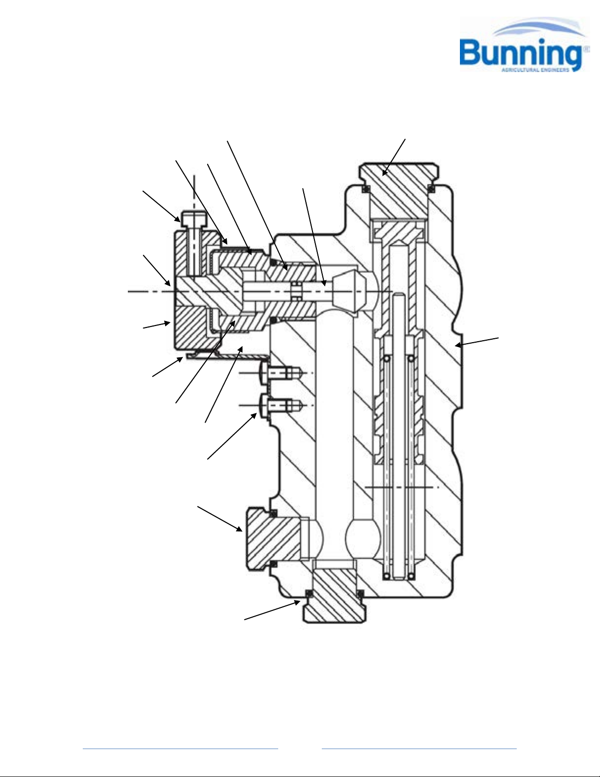
6.5 Hydraulic brake ram assembly 35mm bore. 75 & 76
MK4 90/105/120/150 and WB.
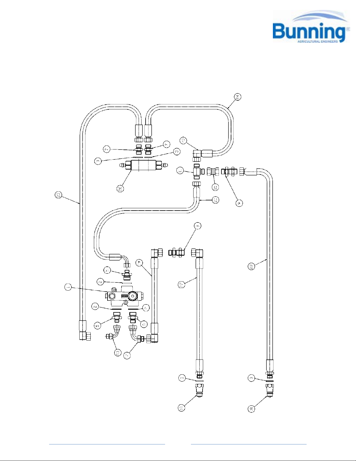
6.6 Hydraulic brake circuit –single axle. 77 & 78
6.7 Hydraulic brake circuit –rear drawbar clevis. 79 & 80
6.8 Hydraulic brake circuit - tandem axles. 81 & 82
7. AXLES & SPRUNG DRAWBAR
Safety notice. 83
General information. 84
Axle maintenance and adjustment. 85 to 96
Minimum program of maintenance sheet. 97
8. TYRES AND WHEELS
8.1 Tyre and wheel maintenance. 98
8.2 Tyre pressure settings. 99
8.3 Wheel type and torque settings. 100

LOWLANDER MK4 MANURE SPREADER –INSTRUCTION & SPARES MANUAL
Page 3
PAGE
9. OPTIONS
9.1 Sprung drawbar. 101 & 102
9.2 Rear clevis drawbar. 103 &104
9.3 Guillotine slurry door MK4. 105 & 106
9.4 Guillotine slurry door MK4 horizontal beaters. 107 & 108
9.5 Guillotine slurry door hydraulic circuit drawing. 109 & 110
9.6 Support Leg. 111
9.7 Toolbox. 112
9.8 Sludge cake kit. 113 & 114
9.9 Detachable Spinner deck kit. 115 & 116
9.10 Installation and gerenal use of detachable spinner deck. 117 & 118
9.11 Handbrake control multi-stroke MS45. 119,120 & 121
10. ELECTRICS
10.1 Wiring for 12v 7 pin plug. 122
10.2 Rear lamps. 123
10.3 Marker lamp. 124
10.4 7 pin connector 125
10.5 7 pin loom. 126
10.6 7 pin lighting circuit 127
10.7 7 pin lighting circuit for rear drawbar 128
11. HEALTH AND SAFETY & POTENTIAL HAZARDS
11.1 Hazardous machinery warning. 129
11.2 Loss of control. 129
11.3 Operation around bystanders. 129
11.4 Hydraulic fluid penetration or burning. 129
11.5 Electrocution. 129
11.6 Body entry. 129
11.7 Coupling / decoupling. 129
11.8 Machinery start up. 130
11.9 Machinery shut down. 130
11.10 Additional driver protection. 130
11.11 PTO Connection and guarding. 130
12. WARRANTY 131
13. IMPORTANT INFORMATION 131
14. NOTES 132
15. TECHNICAL DATA & SPECIFICATIONS 133

LOWLANDER MK4 MANURE SPREADER –INSTRUCTION & SPARES MANUAL
Page 4
1. OPERATING INSTRUCTIONS
The intended purpose of the vehicle is to tow and spread manure and other materials.
1.1 Hitching to tractor.
Attach spreader to pick-up hook or static hitch stub. Do not attach to swinging drawbar
or pick-up hook in extended position.
Remove screwjack from drawbar (if fitted) and locate in transport position provided at
the front of spreader.
Slide the tractor end of the PTO shaft out and fit to the tractor PTO. Lay the two halves
of the PTO shaft alongside one another and mark the required lengths, allowing for
turning. Minimum of 150mm (6 inches) engagement of the two halves. Cut to size and
clean burrs at each end of shaft KEEP SHAFT SLIDING SURFACES GREASED. Attach
chains fitted to PTO guard (to prevent rotation of guard) to suitable point on the tractor
and hole provided on metal cover over PTO shaft on spreader. Ensure that the spring
loaded pins in splined yokes are fully locked in position. Always disengage the PTO
when turning sharply to avoid damage to shafts universal joints. Where a wide angle
PTO is fitted attach this end to the tractor.
1.2 Coupling of hydraulic hoses.
Fit the two hoses for the floor drive hydraulic motor (one to feed and one for return) to
double spool valve on tractor. Choose position of spool lever for ease of control to
obtain floor movement to rear. Reversing of floor is done by selecting the opposite port
of rearward floor movement in tractor cab. Universal quick release probes are fitted as
standard to hose ends. Mark hose as required to assist in the future coupling for correct
position of feed and return. When a slurry door is fitted connect the hydraulic hoses to
a double spool valve and select the hose positions to suit the operator to open and close
the door.
Fit hydrualic brake hose to trailer brake valve on tractor (male fitting).
A universal female brake coupling is fitted as standard to the hose ends.
N.B CHECK DIRECTION OF FLOOR BEFORE LOADING.
Do not run floor in reverse with full load. Speed of floor in reverse is at MAXIMUM.
Only reverse floor for a few seconds.

LOWLANDER MK4 MANURE SPREADER –INSTRUCTION & SPARES MANUAL
Page 5
1.3 Hand brake.
The handbrake is a multi-stroke ratchet type. To apply the handbrake give the handle
short pumps (a clicking of the ratchet will be heard) until resistance occurs and
subsequent tightening of the cable. To release the handbrake give the handle one sharp
movement to the left. This releases the ratchet mechanism.
1.4 Brake adjustment.
Brake adjustment is carried out at the hydraulic brake ram unit fitted to each wheel axle
giving independent adjustment to each wheel. To adjust, jack up the spreader, slacken
the locknut in the set screw and turn the set screw clockwise. (See pages 89 & 90)
BEWARE NOT TO OVER ADJUST. Make sure the wheel can rotate freely.
1.5 Floor adjustment.
When adjusting floor chains ensure that the adjustment is carried out equally to both
sides. ( See page 19)
DO NOT ALLOW THE CHAINS TO BECOME TOO SLACK.
ADJUST CHAINS AFTER A FEW LOADS.
KEEP CHAINS ADJUSTED CORRECTLY AT ALL TIMES, A GUIDE IS TO BE ABLE TO SEE A
WHOLE LINK BELOW FRONT BOTTOM EDGE OF SPREADER i.e. FROM CENTRE TO
FRONT.
Reverse floor
The floor should only be reversed for very short periods, to clear the augers.
Do not reverse if the floor chain is slack, tighten floor chain first. (See page 19)
1.6 Method of operation.
1) Select speed of floor required on control valve.
2) Engage PTO to power the rear augers –tractor engine revs low.
3) Engage spool valve to power floor to rear.
1.7 Slurry Door
As the load height reduces lower the slurry door to cover the augers. This will help
prevent foreign objects being thrown forward.

LOWLANDER MK4 MANURE SPREADER –INSTRUCTION & SPARES MANUAL
Page 6
2. MAINTENANCE
2.1 Lubrication of spreader.
DAILY GREASE Front and rear floor shaft
Overrun clutch to front of main ‘T’ gearbox
WEEKLY GREASE All sealed bearing –2 pumps of grease gun maximum.
TAKE CARE NOT TO DAMAGE GREASE SEAL BY OVERGREASING
Sliding tube of PTO shaft.
PTO universal joints –Follow instructions as for sealed bearings.
Screwjack top (when fitted)
Shearbolt bush
MONTHLY Check gearbox oil levels
ANNUALLY Change oil to all gearbox
TYPE OF LUBRICATION GREASE Multi purpose
GEARBOXES EP90
2.2 Shearbolt Protection.
Only one shearbolt is fitted to the spreader. This is located on the spreader end of the
PTO shaft. The bolt is M10 x 60 grade 6.8 mild steel.
ON NO ACCOUNT MUST A BOLT OF HIGHER GRADE THAN 6.8 TENSILE STRENGTH BE
FITTED.
2.3 Pressure relief valve to floor drive.
This valve is cross line type and fitted to the hydraulic motor on the floor drive gearbox.
The pressure can be varied to suit the material being spread. To adjust, engage the oil
flow via the spool valve on the tractor, slacken the locknut and insert an allen key and
turn clockwise to increase pressure until the floor starts to move. Tighten the locknut.
To decrease the pressure, reverse procedure. When making this adjustment, the
spreader pressure will be set lower than the tractor PRV. A diagram in the floor drive
section of this manual shows which screw relieves forward motion and which screw for
reverse motion of the floor.
It is recommended to apply waste oil to the floor chains periodically when spreading dry
material and particularly at the end of the spreading season. This assists in the smooth
running of the machine and prolongs the working life of the components.

LOWLANDER MK4 MANURE SPREADER –INSTRUCTION & SPARES MANUAL
Page 7
3. FLOOR DRIVE
3.1 HYDRAULIC CIRCUIT FOR FLOOR DRIVE

LOWLANDER MK4 MANURE SPREADER –INSTRUCTION & SPARES MANUAL
Page 8
3.1 HYDRAULIC CIRCUIT FOR FLOOR DRIVE PARTS LIST
KEY QTY PART No. DESCRIPTION
1 1 B3000 FLOW CONTROL
2 3 51593 3/4" BONDED SEAL
3 4 51591 1/2" BONDED SEAL
4 1 51590 3/8" BONDED SEAL
5 2 51337 3/4" TO 3/8"ADAPTOR
6 1 51340 3/4" / 1/2" ADAPTOR
7 2 51336 1/2" TO 3/8" ADAPTOR
8
9 2 51464 1/2" BULKHEAD
10
11 151447 3/8" MALE TEE
12 151412 1/2" MALE/FEMALE 90 DEG
13 151414 3/8" MALE/FEMALE 90 DEG
14
15 151393 1/2" TO 3/8" FEMALE/FEMALE
16
17
18 151576 1/2" MALE PROBE
19 2 B4400 HYD HOSE 230mm
20 1 B4401 HYD HOSE 610mm
21
22 2 B4414 HYD HOSE 2500mm
B4415 EXPORT 2440mm
23 B4416 HYD HOSE FLOW 75
B4418 HYD HOSE FLOW 90
B4420 HYD HOSE FLOW 105
B4422 HYD HOSE FLOW 120
B4424 HYD HOSE FLOW 150
B4426 HYD HOSE FLOW WB
24 B4417 HYD HOSE RETURN 75
B4419 HYD HOSE RETURN 90
B4421 HYD HOSE RETURN 105
B4423 HYD HOSE RETURN 120
B4425 HYD HOSE RETURN 150
B4427 HYD HOSE RETURN WB / 230
26 1 B3068 DOUBLE CROSS LINE RELIEF VALVE

LOWLANDER MK4 MANURE SPREADER –INSTRUCTION & SPARES MANUAL
Page 9
3.2 FLOOR SPEED CONTROL UNIT –PART No. B3000
1
2
3
4
5
6
7
8
9
10
11
12
13
14
15

LOWLANDER MK4 MANURE SPREADER –INSTRUCTION & SPARES MANUAL
Page
10
3.2 FLOOR SPEED CONTROL UNIT –PART No. B3000 PARTS LIST
KEY QTY DESCRIPTION
1 1 O RING
2 1 BACK-UP RING
3 1 O RING
4 1 SET SCREW
5 1 ADJUSTER SCREW
6 1 ADJUSTING KNOB
7 1 INDEX SPRING
8 1 PLUG
9 1 CONTROL SLEEVE
10 1 SCREW
11 1 PLUG
12 1 O RING
13 1 BODY
14 1 PLUG
15 1 NEEDLE VALVE

LOWLANDER MK4 MANURE SPREADER –INSTRUCTION & SPARES MANUAL
Page
11
3.3 FLOOR DRIVE RELIEF VALVES

LOWLANDER MK4 MANURE SPREADER –INSTRUCTION & SPARES MANUAL
Page
12
3.3 FLOOR DRIVE RELIEF VALVES
To adjust relief valve pressure
No.1
Cartridge contols movement of floor to rear. To increase pressure release locknut turn
screw clockwise and retighten locknut.
To decrease pressure turn screw anticlockwise.
No.2
Cartridge controls movement of floor to front. To increase pressure release locknut turn
screw clockwise and retighen locknut.
To decrease pressure turn screw anticlockwise.
NOTE
Maximum protection can be given to moving parts by keeping relief valve pressure set
to a minimum.

LOWLANDER MK4 MANURE SPREADER –INSTRUCTION & SPARES MANUAL
Page
13
3.4 FLOOR DRIVE GEARBOX MK4 75/90/105/120 –B3105
Note:
Motor not shown Part No. B3060

LOWLANDER MK4 MANURE SPREADER –INSTRUCTION & SPARES MANUAL
Page
14
3.4 FLOOR DRIVE GEARBOX MK4 75/90/105/120 –B3105 PARTS LIST
KEY QTY PART No. DESCRIPTION
1 1 B3203 CASING
2 1 B3228 SLEEVE M50
2 1 B3229 SLEEVE M60 (W.B BEATERS)
3 1 B4099 CIRCLIP
4 1 B3231 GEAR
5 2 B3869 BEARING
6 2 B9069 CIRCLIP
7 1 B3237 PINION SHAFT
8 2 B2271 KEY
9 1 B3234 GEAR
10 2 B3863 BEARING
11 3 B4006 CIRCLIP
12 1 B3232 PINION SHAFT
13 1 B2270K KEY
14 1 B3238 CROWN BEVEL
15 1 B3478 SPACER
16 2 B3865 BEARING
17 2 B4002 CIRCLIP
18 1 B3233 PINION SHAFT
19 1 B3862 BEARING
20 1 B4019 CIRCLIP
21 2 B3997 BREATHER PLUG
22 2 B3995 SIGHT GUAGE
23 2 B3921 CAP SEAL
24 2 B3922 CAP SEAL
25 2 B3946 SEAL
26 1 B3222 GASKET
27 1 B3218 COVER PLATE
28 8 73030/1 BOLT
29 1 B3226 GASKET

LOWLANDER MK4 MANURE SPREADER –INSTRUCTION & SPARES MANUAL
Page
15
3.5 FLOOR DRIVE GEARBOX MK4 150 –B3120

LOWLANDER MK4 MANURE SPREADER –INSTRUCTION & SPARES MANUAL
Page
16
3.5 FLOOR DRIVE GEARBOX MK4 150 –B3120 PARTS LIST
KEY QTY PART No. DESCRIPTION
1 1 B3204 CASING
2 1 B3230 SLEEVE
3 1 B4030 CIRCLIP
4 1 B3236 GEAR
5 2 B3868 BEARING
6 2 B4016 CIRCLIP
7 1 B3240 PINION
8 2 509560 KEY
9 1 B3244 GEAR
10 2 B3867 BEARING
11 2 B4012 CIRCLIP
12 1 B3242 PINION
13 1509554 KEY
14 1 B3248 CROWN GEAR
15 2 B3864 BEARING
16 3 B4006 CIRCLIP
17 1 B3252 PINION
18 1 B3862 BEARING
19 1 B4019 CIRCLIP
20 2 B3997 BREATHER BUNG
21 2 B3995 SIGHT GLASS
22 2 B3922 CAP SEAL
23 2 B3926 CAP SEAL
24 2 B3948 SEAL
25 1 B3224 GASKET
26 1 B3220 COVER PLATE
27 8 73030/1 BOLT
28 1 B3226 GASKET

LOWLANDER MK4 MANURE SPREADER –INSTRUCTION & SPARES MANUAL
Page
17
3.6 REAR FLOOR SHAFT ASSEMBLY

LOWLANDER MK4 MANURE SPREADER –INSTRUCTION & SPARES MANUAL
Page
18
3.6 REAR FLOOR SHAFT ASSEMBLY PARTS LIST
KEY QTY PART No. DESCRIPTION
1 1 B2250 REAR SHAFT M50
1 B2254 REAR SHAFT M60 MK4 150 ONLY
1 B2256 REAR SHAFT M60 MK4 WITH W.B BEATERS
2 2 B2100 GYPSY WHEEL M50 MK4 75-120
2 B2301 GYPSY WHEEL M60 MK4 WITH W.B BEATERS
3 2 B2300 BEARING FLANGE M50
2 B2302 BEARING FLANGE M60
4 2 B2320 ACM BUSH M50
2 B2322 ACM BUSH M60
5 2 B2280 END PLATE M60
614 73556 NUT & BOLT M14
7 4 BOLT M12 x 35
8 1 B3105 GEARBOX 75/90/105/120
1 B3106 GEARBOX WITH W.B BEATERS
1 B3120 GEARBOX 150 ONLY
9 1 B3212 TORQUE PLATE 75/90/105/120
1 B3214 TORQUE PLATE 150 ONLY
10 1 B3060 HYDRUALIC MOTOR
1 B3070 HYDRUALIC MOTOR MK4 150 ONLY
11 2 B2274 KEY FOR M50 SHAFT
2 B2275 KEY FOR M60 SHAFT
12 1 B2277 KEY FOR M50 SHAFT
1 B2278 KEY FOR M60 SHAFT
13 1 B2348 SPACER 150 ONLY
14 4 WASHER SPRING WASHER M12

LOWLANDER MK4 MANURE SPREADER –INSTRUCTION & SPARES MANUAL
Page
19
3.7 FRONT SHAFT AND CHAIN ASSEMBLY

LOWLANDER MK4 MANURE SPREADER –INSTRUCTION & SPARES MANUAL
Page
20
3.7 FRONT SHAFT AND CHAIN ASSEMBLY PARTS LIST
KEY QTY PART No. DESCRIPTION
122 B2010 CHANNEL FLOOR SLAT MK4 75
28 B2010 CHANNEL FLOOR SLAT MK4 90/105
30 B2010 CHANNEL FLOOR SLAT MK4 120
33 B2010 CHANNEL FLOOR SLAT MK4 150
43 B2015 BOX FLOOR SLAT MK4 75
55 B2015 BOX FLOOR SLAT MK4 90/105
59 B2015 BOX FLOOR SLAT MK4 120
65 B2015 BOX FLOOR SLAT MK4 150
2 2 B2286 ADJUSTERS M24 MK4
2 B2288 ADJUSTERS M30 MK4 150 ONLY
3 2 B2202 JOINER LINK
4 2 B2126 FRONT CLEANER
5 4 73031 BOLT
6 2 B2320 BUSH M50
2 B2322 BUSH M60 MK4 150 ONLY
7 2 B2290 BEARING HOUSING M50
2 B2294 BEARING HOUSING M60 MK4 150 ONLY
8 2 B2345 SPACER M50
2 B2346 SPACER M60 MK4 150 ONLY
9 1PR B2152 FLOOR CHAIN 28FT FOR CHANNEL SLATS MK4 75
1PR B2162 FLOOR CHAIN 35FT FOR CHANNEL SLATS MK4 90/105
1PR B2172 FLOOR CHAIN 37FT FOR CHANNEL SLATS MK4 120
1PR B2182 FLOOR CHAIN 40FT FOR CHANNEL SLATS MK4 150
1PR B2154 FLOOR CHAIN 28FT FOR BOX SLATS MK4 75
1PR B2164 FLOOR CHAIN 35FT FOR BOX SLATS MK4 90/105
1PR B2174 FLOOR CHAIN 37FT FOR BOX SLATS MK4 120
1PR B2184 FLOOR CHAIN 40FT FOR BOX SLATS MK4 150
10 1 B2220 SHAFT M50
1 B2222 SHAFT M60 FOR MK4 150 ONLY
11 1 B2214 PLATE WHEEL SET OF 4
1 B2218 PLATE WHEEL SET OF 4 MK4 150 ONLY
12 250726 GREASE NIPPLE
This manual suits for next models
4
Table of contents
Other BUNNING Spreader manuals
Popular Spreader manuals by other brands

Branick Industries, Inc.
Branick Industries, Inc. 5700E Installation, Operation & Repair Parts Information

Ecolawn
Ecolawn ECO250 Operator's manual

Precision
Precision SB15000OSP owner's manual

Trynex
Trynex SnowEx SP-1575 owner's manual

PermaGreen Supreme
PermaGreen Supreme Triumph A1A Operator's manual

KUHN
KUHN PROPUSH 2000 Series Operator's manual