Neilsen CT2205 User manual

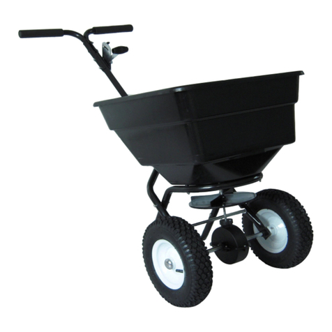
80LB WALK BEHIND SPREADER CT2205
INSTRUCTION MANUAL
SAVE THESE INSTRUCTIONS AND PRECAUTIONS.
READ ALL PRECAUTONS AND INSTRUCTIONS BEFORE USE.
Cannon Tools Limited
Address: 20 Station Road, Rowley Regis, West Midlands, B65 0JU.U.K.

1
EC DECLARATION OF CONFORMITY
We CANNON TOOLS LTD
20 Station road, Rowley Regis, West Midlands,B65 0JU.U.K.
Declare that the following machine complies with the appropriate basic safety
and health requirements of the EC Directive based on its design and type, as
brought into circulation by us.
In case of alteration of the machine, not agreed upon by us, this declaration will
lose its validity.
Product description: WALK-BEHIND SPREADER
Model: CT2205
Applicable EC Directives:
EC Machinery Directive 2006/42/EC
Harmonized standards
EN ISO 12100:2010, EN ISO 13854:2019,
EN ISO 14120:2015, EN ISO 13857:2019
20 Station Road, Rowley Regis, West Midlands, B65 0JU.U.K.
Mr. Gurcharan Tony Singh Sanghera
Managing Director
CANNON TOOLS LTD
sign
Gurcharan Tony Singh Sanghera
2021-07-05

2
1. SPECIFICATIONS
Capacity: 80LB
Spread Width: 10'-12'/3048mm-3658mm
Pneumatic Tire: 12"
Heavy duty Nylon gear
Rate setting control on handle for precise adjustments
Accessories: screen & rain cover
2. GENERAL SAFETY INSTRUCTIONS
Warning: When using tool, basic safety precautions should always be followed to
reduce the risk of personal injury and damage to equipment. Read all instructions
before using this tool!
STAY ALERT. Do not operate the machine while under the influence of drugs,
alcohol, or any medication that could affect your ability to use it properly. Do not
use this machine when you are tired or distracted from the job at hand. Be aware
of what you are doing at all times. Use common sense.
AVOID DANGEROUS CONDITIONS. Make sure there is adequate surrounding
workspace. Cluttered areas invite injuries. Keep your work area clean with
sufficient light. Keep the area around the machine clear of obstructions, grease,
oil, rubbish & other debris which could cause persons to fall onto moving
parts.
INSPECT YOUR MACHINE. Check all bolts, nuts & screws for tightness before
each use, especially those securing guards & drive mechanisms. Vibration
during use, may cause these to loosen. Replace damaged, missing or
failed parts before using. Warning labels carry important information. Replace
any missing or damaged warning labels.
CRUSH AND CUT HAZARDS. Always keep your hands and feet clear from
moving parts while operating the equipment. Always keep the work area clean
and clear when operating.

3
CONDITIONS. We recommend the machine is not used during winds. This may
affect the spreading pattern.
DRESS PROPERLY. Do not wear loose clothing, gloves, scarfs, neckties
or jewellery (rings, wrist watches), which can be caught in moving parts.
DO NOT OVERREACH. Keep proper footing and balance at all times
when using the machine. Never stand on the machine. Serious injury could occur
if the machine is tipped or if the moving parts are unintentionally contacted. Do
not store anything above or near the machine, where anyone might stand on the
machine to reach them.
AVOID INJURY FROM UNEXPECTED ACCIDENT. Keep hands & feet out of the
way of all moving parts. Do not place any part of your body or any tool e.g. in
moving parts of the machine during operation.
DO NOT FORCE TOOL. Always work within the rated capacity. Do not operate
for a purpose for which it was not intended.
MAINTAIN YOUR MACHINE WITH CARE. Clean the machine immediately after
use. Keep the machine clean to ensure it operates to its full & safest
performance. When maintaining this machine, only the manufacturer’s original
replacement parts should be used.
PROTECT THE ENVIRONMENT. Take left over materials to an authorised
collection point or follow the stipulations in the country where the machine is
used. Do not discharge into drains, soil or water.
STORE IDLE EQUIPMENT. When not in use, the machine should be stored in a
dry location. Keep the machine away from children and others not qualified to
use it.
OPERATION SPEED. Do not exceed 6 mph, to avoid personal injury and/or
equipment damage.
TYRE INFLATION. WARNING! Over-inflated tyres can explode and cause
serious injury. Avoid injury by NEVER over inflating tyres beyond the maximum
pressure printed on the side of the tyre wall. ALWAYS use FOOT or HAND pump
inflation devices.
This is a garden/domestic product, therefore extended use over abrasive
surfaces (e.g. concrete, tarmac etc.) could cause premature wear on the tyres.

4
3. CONTROLS AND FEATURES IDENTIFICATION
Read this owner’s manual before operating the equipment. Familiarize yourself
with the location and function of the controls and features. Save this manual for
future reference.
1) Flow Control – Controls the flow of material being spread.
2) Handle – Pushes and moves the spreader easily.
3) Support Leg – Stabilizes load and spreader.
4) Tires / Wheel – Do not exceed recommended rated pressure.
5) Impeller - Evenly distributes material.
6) Hopper – Do not exceed rated load capacity 80lb
7) Rain cover

5
4. ASSEMBLY AND OPERATING INSTRUCTIONS
1. HELPFUL HINTS:
READ THE INSTRUCTIONS BEFORE ASSEMBLY
If your spreader does not spread evenly, be sure the FRONT on the gear box
points to the front of the spreader. The impeller must turn clockwise.
Reversing the gear box will cause the impeller to turn counter clockwise.
Clean the impeller plate after each use. Fertilizer stuck on the impeller blades
will cause uneven spreading.
Your spreader is designed to be pushed at three miles per hour, which is a
brisk walking speed. Slower or faster speeds will change the spread patterns.
Wet fertilizer will also change the spread pattern and flow rate. Clean your
spreader thoroughly after each use. Wash between the shut off plate and
bottom of the hopper.
Gears are permanently lubricated at the factory. Do not open the gear box or
dirt may enter.
2. Remove and identify loose parts from carton and bag.

6
STEP 1: Install impeller onto the
Gear Box & Axle Assembly.
Insert Screw M4x20 through
impeller then through Gear Box
Axle.

7
STEP 2: Attach the Wheel Assembly Frame on each side of the Gear Box Axle
and Fixing Connecting Rod, insert two bolts M6x35 into the Fixing Connecting
Rod through Wheel Assembly Frame. Make sure the hole on Axle of Gear Box is
on the right side when assembly as shown. Attach Wheel Assembly Frames and
Support Leg onto Hopper using bolts M6x70, lock nuts M6 and Big Flat Washers
Ø6. Note: The bolts and nuts needn't be tightened yet.
Bolt
M6x35
M6x35
Bolt
M6x35

8
STEP 3: Insert Inner Axle Bushing into Outer Axle Bushing and make sure they
are tight neatly. Install right Wheel Assembly to right Axle using bolt M5x45 and
lock nut M5, and then install the Cap onto right Axle using a wooden or rubber
hammer. Now install left Wheel Assembly to left Axle, put a flat washer Ø16 and
install the Cap onto left Axle using a wooden or rubber hammer.

9
STEP 4: Insert Upper Handle into the Support Leg and tighten using bolts M6x40
and Lock Nuts M6. NOW GO BACK AND TIGHTEN ALL NUTS AND BOLTS
STARTING WITH FIRST STEP. DO NOT OVER TIGHTEN.

10
STEP 5: (1) Insert the Steel Wire head of control cable into the small hole on
Gauge and Lever Assembly. (2)Release two bolts M5x10 and lock nuts on Press
Plate. (3) Put the Plastic Tube into the slot of Press Plate. (4) Tighten two bolts
M5x10 and lock nuts again. (5). Insert R Pin.

11
STEP 6: ADJUSTMENTS. When you have finished all above steps, and if you
find the holes at the bottom of hopper can close and open completely by using
the handle . You don't need to do the following steps. If it do not close and open
completely, you may need to do the following steps. (1)Release two bolts M5x10
on clamp as shown. (2). Push the handle to the top position, use your hand to
adjust the adjustable plate so as to make sure the hole at the bottom of hopper
can be closed completely. (3). Push the handle to the lowest position, use your
hand to adjust the adjustable plate so as to make sure the hole at the bottom of
hopper can be opened completely. (4). And then tighten the bolts and nuts on
clamp again.
To operate this spreader, push the handle to the lowest position (downwards).
You may move the position of Wing nut on the Gauge & Lever to adjust the
space on the hole between the hopper and the adjustable plate as per your need
when spreading.

12
5. MAINTENANCE AND STORAGE
MAINTENANCE
● Rinse/dry inside and outside of the aerator spreader after each use.
●Regularly grease axle and wheel bearing area or when needed.
● Periodically check all fasteners for tightness.
● Annually clean and lightly lubricate spike assembly and shaft or when needed.
● Use a glossy enamel spray paint to touch up scratched or worn painted metal
surfaces.
● Spikes periodically need to be sharpened with a small grinder to maintain good
penetration.
● Never exceed load capacity rating of 100lbs it will damage the equipment..
IMPORTANT:
If a part needs replacement, only use parts that meet the manufacturer’s
specifications. Replacement parts that do not meet specifications may result in a
safety hazard or poor operations.
STORAGE
● Never allow material to be stored in the hopper for extended periods of time.
● Before storing make sure the aerator spreader is clean and dry for years of
trouble free service.
● Lightly lubricate all metal surfaces and moving parts to prevent rust.
● Store indoors or protected area during severe weather and winter months.

13
6. PARTS DRAWING

14
PARTS LIST
Ref#
Description
Qty
Ref#
Description
Qty
1
Carriage Bolt M6x25
1
26
Support Leg
1
2
External-tooth Washer Ø8
1
27
Wheel Assembly Frame(Right)
1
3
Gauge and Lever Assembly
1
28
Thin Washer
1
4
Adjust Handle Pole
1
29
Pneumatic Wheel
2
5
Adjust Handle A
1
30
Flat Washer Ø16
1
6
Adjust Handle B
1
31
Axle End Cover
2
7
Screw M4x18
1
32
Inner Axle Bushing
2
8
Handle Grip
1
33
Outer Axle Bushing
2
9
Spacer
1
34
Gear Box & Axle Assembly
1
10
Wing Nut
1
35
Screw M4x20
1
11
Hopper
1
36
Hex Bolt M5x45
1
12
R Pin Ø2x60
1
37
Line Clamp Press Plate
2
13
Center Cover
1
38
Control Rod
1
14
Hex Bolt M6x70
4
39
Screw M5x10
2
15
Rivet Ø5X12
4
40
Nylon Washer
1
16
Fixed Adjustable Plate
1
41
Big Flat Washer Ø6
5
17
Screw M5x16
2
42
Handle
1
18
Wheel Assembly Frame(Left)
1
43
Active Adjustable Plate
1
19
Impeller
1
44
Lock Washer Ø6
1
20
Hex Bolt M6x35
5
45
Big End Cap
1
21
Lock Nut M5
5
46
Small End Cap
2
22
Line Clamp Bottom Plate
1
47
Fixing Connection Rod
1
23
Tube End Cap
4
48
Hopper Screen
1
24
Hex Bolt M6x40
4
49
Rain Cover
1
25
Lock Nut M6
12

15
CANNON TOOLS LTD
Add: 20 station road, Rowley Regis, west midlands,B65 0JU.U.K.
Made in China
Table of contents
Other Neilsen Spreader manuals
Popular Spreader manuals by other brands

KUHN
KUHN MDS 55 Operator's manual

Egholm
Egholm City Ranger 3070 Operator's manual

Lesco
Lesco Commercial plus 705698 Parts list and instructions

CynkoMet
CynkoMet DZIK N-200 Instructions for Use and Operation

Shindaiwa
Shindaiwa HomePro 76RS owner's manual

Trynex
Trynex SnowEx SP-7550 Owner's/operator's manual

Rotomec
Rotomec Baby-Hop 50 Series Operator's manual

H&S
H&S 3131 Operator's manual

Western
Western PRO-FLO 300W Owner's manual and installation instructions

Chapin
Chapin SureSpread 80088 Assembly / operation instructions / parts

Ryobi
Ryobi OSS1800 Original instructions

Amkus
Amkus AMK-24 User's information manual