MAGUIRE MPL Series Owner's manual

MAGUIRE PRODUCTS INC.
MAGUIRE
MPL Series - ML Series
VENTURI LOADERS
INSTALLATION OPERATION MAINTENANCE
Original Instructions Manual
Revision Date: April 8, 2019
Copyright Maguire Products, Inc. 2019

M A G U I R E P R O D U C T S , I N C .
2
M P L M L S e r i e s V e n t u r i L o a d e r s

M A G U I R E P R O D U C T S , I N C .
3
M P L M L S e r i e s V e n t u r i L o a d e r s
Maguire Products Inc.
VENTURI LOADERS
MPL Models: MPL, MPL-A, MPL-AS
ML Models: ML-1, ML-2, ML-3, ML-4
-M for Micro blender Models
-A for Alarm Models
Table of Contents
Available Models ____________________________________________5
Parts Supplied ______________________________________________6
Assembly __________________________________________________7
Installation / Assembly Diagrams _______________________________9
Operation _________________________________________________16
Controls __________________________________________________17
Adjustments _______________________________________________18
Troubleshooting ____________________________________________18
Wiring Diagrams ___________________________________________19
Warranty __________________________________________________22
Technical Support and Contact Information _____________________23

M A G U I R E P R O D U C T S , I N C .
4
M P L M L S e r i e s V e n t u r i L o a d e r s
Copyright
2019 Maguire Products Inc.
The information contained within this manual including any translations thereof, is the property of
Maguire Products Inc. and may not be reproduced, or transmitted in any form or by any means
without the express written consent of Maguire Products Inc.
To every person concerned with use and maintenance of the Maguire MPL Series – ML Series
Venturi Loader it is recommended to read thoroughly these operating instructions. Maguire
Products Inc. accepts no responsibility or liability for damage or malfunction of the equipment arising
from non-observance of these operating instructions.
To avoid errors and to ensure trouble-free operation, it is essential that these operating instructions
are read and understood by all personnel who are to use the equipment.
Should you have problems or difficulties with the equipment, please contact Maguire Products Inc.
or your local Maguire distributor.
These operating instructions only apply to the equipment described within this manual.
For the latest revision of this manual, visit www.maguire.com
Manufacturer’s Contact Information
Maguire Products Inc.
11 Crozerville Road
Aston, PA. 19014
Phone: 610.459.4300
Fax: 610.459.2700
Website: http://www.maguire.com
Email: info@maguire.com

M A G U I R E P R O D U C T S , I N C .
5
M P L M L S e r i e s V e n t u r i L o a d e r s
AVAILABLE MODELS
All VENTURI LOADER MODELS use our aluminum venturi vacuum generator.
MPL series loaders:
Are built on a two inch steel bar for easy mounting to the
frame of a concentrate feeder or Weigh Scale Blender.
The air solenoid is visible on the bar.
Only ONE venturi loader can be controlled.
MPL has no separate control box.
MPL-A has a control box with ALARM Strobe light and beeper.
MPL-AS uses the same control box with an additional time delayed solenoid to activate a shut
down procedure in the event the ALARM goes unattended.
ML series loaders:
Do not use a steel bar for mounting.
The air solenoids are enclosed in the control box.
Up to FOUR venturies can be controlled from one box.
An ALARM feature is available, but no shut down function.
ML-1: Controls 1 venturi only, for loading one hopper.
The control panel accommodates ONE switch only.
ML-2, ML-3, and ML-4:
The control panel accommodates up to FOUR switches to
control FOUR venturi loaders.
The number installed determines the model number.
Add "M" to the model number:
when the unit is to be mounting on a MICRO Blender (ML-1M).
Add "A" to the model number:
when an ALARM function is required (ML-1A).

M A G U I R E P R O D U C T S , I N C .
6
M P L M L S e r i e s V e n t u r i L o a d e r s
PARTS SUPPLIED
All MODELS:
1. Aluminum VACUUM GENERATOR, mounts directly to the material pickup lance.
2. MATERIAL PICK-UP LANCE.
3. MATERIAL TRANSFER LINES:
a) Suction line (12 feet of 1 inch flexible hose).
b) Material pick-up lance (aluminum).
4. AIR LINE (Plastic) to connect the air solenoid to the Vacuum Generator.
5. HOPPER LID PARTS:
On MICRO blender series, (ML-1M), a complete new lid is provided with
filtered receiver box.
All others, a PELLET DEFLECTOR box is provided to mount inside the
hopper lid to accept the inflow of material.
6. SENSOR MOUNT (red polypropylene) installs in the hopper or lid.
7. LEVEL SENSOR, fits into the sensor mount.
8. CONTROL BOX, varies depending on model. (none for model MPL)
MPL, MPL-A, MPL-AS only:
1. Steel SUPPORT BAR with:
a) Air solenoid valve
b) Air pressure gauge
c) Low Level sensor
MPL-A, MPL-AS only:
1. Controller mounting bracket, included if loader control is attached to a WSB additive
feeder.
PACKAGED for SHIPPING:
ALL models: The PICK-UP lance is shipped in one carton.
MPL series: All remaining parts are shipped in one additional carton.
ML series: The controller is in one carton.
Parts for each venturi loader are shipped one additional carton per loader.

M A G U I R E P R O D U C T S , I N C .
7
M P L M L S e r i e s V e n t u r i L o a d e r s
ASSEMBLY (Refer to diagrams)
MPL series:
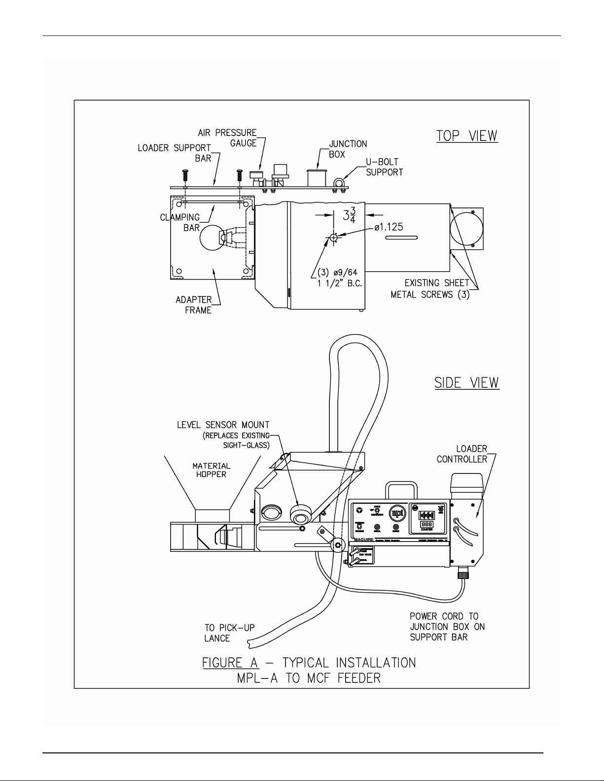
1. Attach the Steel SUPPORT BAR to the ADAPTOR FRAME as shown in Figure A. To do
so, remove one bolt, slide clamping bar behind two corner angles; re-install bolt and
tighten. On a concentrate feeder, the bar attaches to the REAR of the adaptor frame and
extends BEHIND the controller.
All Models:
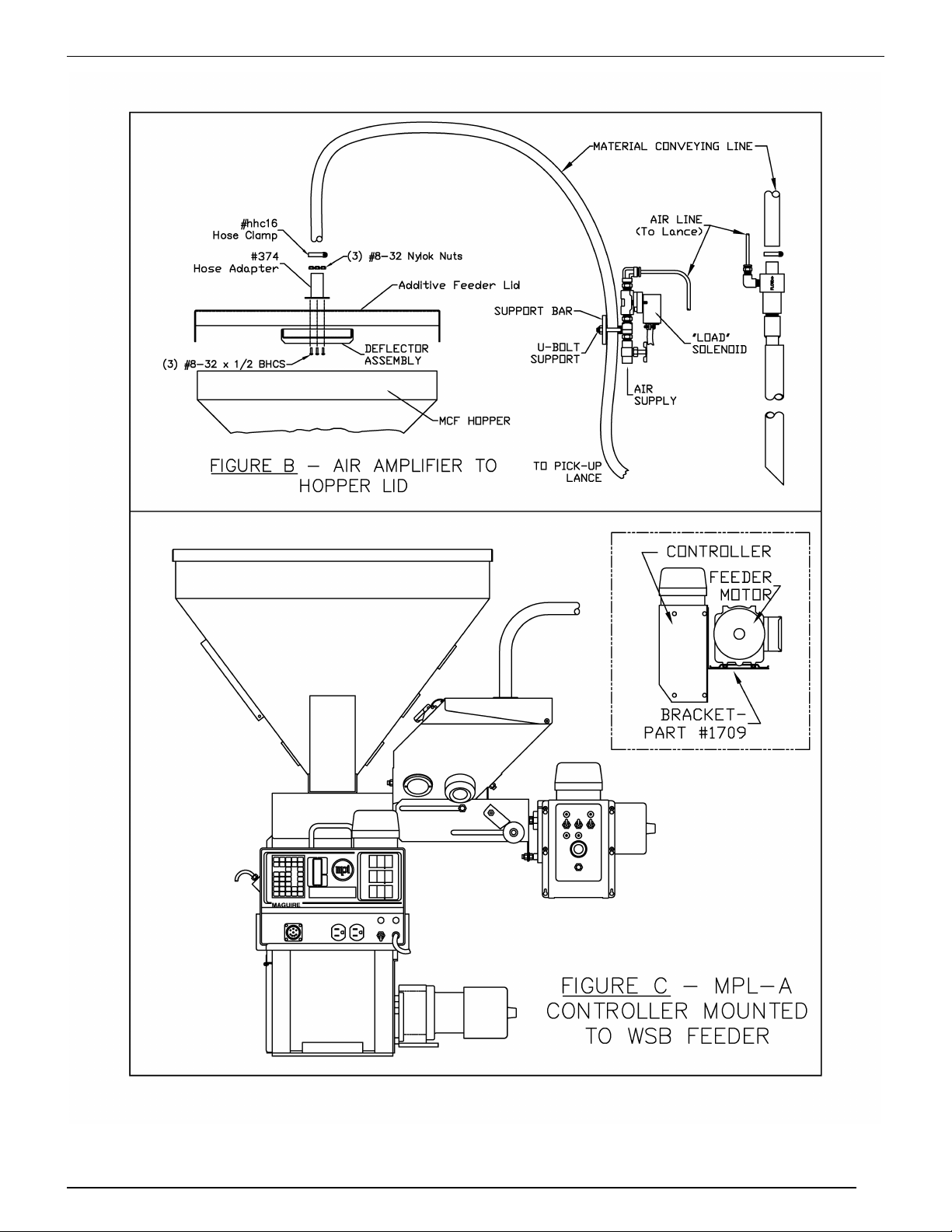
2. Mount the deflector and connection stub tube to the hopper lid as shown in Figure B.
NOTE: OLDER HOPPER LIDS:
If this unit is being added to an older hopper lid, you must first add the new hole
pattern to your existing hopper lid. The hole pattern is shown in Figure A.
NOTE: MICRO BLENDERS:
Replace the standard lid with the new lid provided.
3. Connect the red material suction hose to the top of the lid.
NOTE: MPL series models with SUPPORT BAR:
Secure this hose to the SUPPORT BAR using the "U" bolt provided. Adjust so
that there is NO STRAIN on the hopper lid.
4. Attach the other end of the red material hose to the venturi / pick-up lance provided.
5. Run the air line from the air solenoid to the venturi.
6. Install the SENSOR MOUNT into the hopper in place of one of the viewing windows. On
Concentrate feeder hoppers, with augers, remove the rear-most window on the operator
side (the same side as the controller front and nearest the controller). Use a 1/8" drill to
remove the window rivets. Install sensor mount using #6 sheet metal screws provided.
7. Install the gray (35 mm) level sensor into this mount. Secure with the rubber ring or by
tightening the hold down screw.
8. An air supply line of at least 80 PSI must be connected. A "quick disconnect" fitting is
recommended. Airflow requirement is about 16 CFM. A 3/8" I.D. supply line is adequate.
Lower pressures and smaller I.D. lines may, or may not be adequate.

M A G U I R E P R O D U C T S , I N C .
8
M P L M L S e r i e s V e n t u r i L o a d e r s
MOUNTING CONTROL BOXES (all models except MPL)
On MCF AUGER FEEDERS:
If this loader to be used with an MCF concentrate feeder, attach the control box to the end of the
Feeder control box as shown in Figure A. This can be done using the existing sheet metal screws
in the MCF controller.
WEIGH SCALE BLENDERS:
If this loader is to be used with a Weigh Scale Blender FEEDER, then a bracket is provided. Bolt
this bracket to the plate that is mounted under the auger feeder drive motor and then bolt the
loader control box to the bracket. This is shown in Figure C.
MICRO BLENDERS and OTHER EQUIPMENT:
If we have not provided a separate mounting bracket for the controller, then you should select
whatever position or location that serves your needs best.

M A G U I R E P R O D U C T S , I N C .
9
M P L M L S e r i e s V e n t u r i L o a d e r s
DIAGRAMS - VENTURI COLOR LOADER - 7 PAGES
Figure A

M A G U I R E P R O D U C T S , I N C .
10
M P L M L S e r i e s V e n t u r i L o a d e r s
Figure B and C

M A G U I R E P R O D U C T S , I N C .
11
M P L M L S e r i e s V e n t u r i L o a d e r s
Lid and lance details (wide diagram)

M A G U I R E P R O D U C T S , I N C .
12
M P L M L S e r i e s V e n t u r i L o a d e r s
ML-1

M A G U I R E P R O D U C T S , I N C .
13
M P L M L S e r i e s V e n t u r i L o a d e r s
ML 2/3/4

M A G U I R E P R O D U C T S , I N C .
14
M P L M L S e r i e s V e n t u r i L o a d e r s
ML - 2MB

M A G U I R E P R O D U C T S , I N C .
15
M P L M L S e r i e s V e n t u r i L o a d e r s
WSB-MB & ML-2

M A G U I R E P R O D U C T S , I N C .
16
M P L M L S e r i e s V e n t u r i L o a d e r s
OPERATION
When material level in the hopper drops enough to uncover the sensor, the air solenoid is turned
on. High pressure air passing through the vacuum generator creates a high volume, low
pressure, flow of air into the hopper. This flow of air pulls material from the source and conveys it
into the hopper.
A steel plate in the hopper serves to deflect the blast of pellets and slow their speed. This
prevents high speed bouncing of pellets in the hopper, keeping them from escaping under the
edges of the hopper lid. The Air stream is expected to escape from the hopper by passing under
the edge of the lid. The lid must not be gasketed.
When the sensor is covered, loading stops. It is not unusual for load times to be short. While you
may be accustomed to seeing other loaders go through lengthy load time cycles, if this loader
cycles on for only a few seconds, it is an indication that the unit is loading quite well.
ALARM models
If the letter "A" is part of the model designation on MPL-A (not the ML-A), then you have a control
box with an ALARM function. In this case a timer is running whenever the venturi is loading. If
loading continues for two minutes, the timer will turn on the strobe light and beeper alarms
automatically.
On model MPL-AS only, if five more minutes pass without the sensor being covered, a third
device is turned on. This signal will drive a shut down circuit, either a relay that is wired to stop
your process, or an air operated flow control gate, that stops the flow of pellets to the process.
At any time, if the sensor is covered for even a moment, the alarms reset and timers are reset to
zero.
Timers are preset for 2 minutes and 5 minutes, respectively. These times can be changed by
moving jumpers on the board. Note: The ML-A does not have a timer adjustment. On the ML-A .
the alarm is set for 2 minutes, meaning that if a sensor is not re-covered within 2 minutes the
controller will alarm.

M A G U I R E P R O D U C T S , I N C .
17
M P L M L S e r i e s V e n t u r i L o a d e r s
CONTROLS
MODEL MPL: has no control box. Loading is simply controlled by
uncovering the sensor.
MODELS MPL-A and MPL-AS:
1. SWITCHES:
LEFT switch is the LOADER control.
MIDDLE switch is the ALARM control.
RIGHT switch is the optional process SHUT-DOWN control. This "shut-down" function
requires an air operated mechanical shut-off device mounted to an adaptor frame
(as supplied standard with our concentrate feeders). When energized, this will
stop the flow of natural material to the process.
2. SWITCH POSITIONS:
UP for automatic operation.
MIDDLE position to prevent operation of the associated function.
DOWN position to force ON, or TEST the associated function.
3. PILOT LIGHTS:
UPPER LEFT and RIGHT indicate the associated function is ON.
LOWER LEFT indicates ALARM DELAY TIMER is running (blinking).
If the loader does not load within 2 minutes, the
ALARMS will be actuated.
LOWER MIDDLE indicates SHUT-DOWN DELAY TIMER is running (blinking).
MODELS ML-1, ML-2, etc:
1. SWITCHES:
Each venturi has an ON/OFF switch associated with it.
An integral pilot light lights when turned on.
2. ALARMS:
If an ALARM is provided, it is fully automatic. Models controlling
two or more venturies, the one ALARM activates for any single
venturi failure to load.

M A G U I R E P R O D U C T S , I N C .
18
M P L M L S e r i e s V e n t u r i L o a d e r s
ADJUSTMENTS
1. AIR FLOW CONTROL VALVE:
The idea is to use as little air as possible and still convey pellets. Conveying can occur with
as little as 20 PSI air. Read and adjust the pressure gauge WHILE CONVEYING, to
determine correct conveying pressure. If pressure drops too low for proper operation, the
diameter of the AIR SUPPLY line is TOO SMALL.
Too much air flow wastes air and may create dust problems. Pellets may bounce out of
the hopper from under the lid.
A very low flow of air may not convey pellets properly. Use just enough air to ensure a
steady continuous flow.
2. LEVEL SENSOR:
The SENSOR should be adjusted to "turn on" when about half of the sensor holder is
covered. A very small screwdriver is required for adjustments. The adjustment screw and
on/off pilot light are located in the back of the sensor. Be sure sensor is always fully seated
in the sensor holder.
TROUBLESHOOTING
FAILURE TO CONVEY MATERIAL:
1. Check that air supply is adequate.
Check the PRESSURE GAUGE while loader is ON. It should read between 20 and 80 PSI
WHILE LOADING.
2. Check for obstructions in the conveying line.
3. Disconnect the material line from the venturi loader and confirm that the venturi moves air
correctly with the material line removed.
DUST problems:
We rely on the loose fit of the lid to allow air to escape from the hopper. The loader will not
work if you gasket the lid. Over time, a small amount of dust may accumulate on the
outside of the hopper. If this is a problem, we can punch a large (3 inch) hole in the lid and
add an automotive style air filter to the top of the lid. Thin gasketing can then be added to
the underside of the hopper lid.
A draw back is that this becomes a possible source of cross color contamination and is
also an occasional maintenance item. We believe it is simpler to clean off this dust when
color changes are made, thereby avoiding the maintenance required by the addition of a
filter.

M A G U I R E P R O D U C T S , I N C .
19
M P L M L S e r i e s V e n t u r i L o a d e r s
Wiring Diagrams (3 pages)

M A G U I R E P R O D U C T S , I N C .
20
M P L M L S e r i e s V e n t u r i L o a d e r s
This manual suits for next models
13
Table of contents
Other MAGUIRE Industrial Equipment manuals