SSP EDI Series User manual

Table of Contents
Version 1.0
March 2019
EDI B | EDI C | EDI D | EDI E
Stop button | Emergency stop/Emergency stop button
EN Operating Manual
SSP Safety System Products GmbH & Co. KG
Max-Planck-Str. 21
D-78549 Spaichingen
www.safety-products.de
3 Installation ...............................................3
3.1 General installations notes .........................................3
3.2 Installation of the build-in version EDI Slimline housing ....................3
4 Technical data .............................................4
4.1 Switch elements .................................................4
5 Commissioning and Maintenance ..............................5
5.1 Function Test ...................................................5
5.2 Periodic inspection ...............................................5
5.3 Behavior in the event of a malfunction ................................5
6 Disassembly and Disposal ....................................5
6.1 Removal.......................................................5
6.2 Disposal .......................................................5
7 Electrical connection........................................5
7.1 Pin assignment..................................................5
8 Declaration of Conformity....................................6
8.1 EC conformity regulations..........................................6
1 About This Document .......................................2
1.1 Function.......................................................2
1.2 Safety instruction for the authorized skilled personnel......................2
1.3 Symbols .......................................................2
1.4 Scope of application ..............................................2
1.5 Attention: Safety Instructions .......................................2
1.6 Attention: Incorrect use............................................2
1.7 Liability Disclaimer ...............................................2
2 Product Description.........................................2
2.1 Intended Use ...................................................2
2.2 Design types....................................................2
2.3 Scope of application and mode of action...............................2
2.4 Product characteristics ............................................2
2.5 Dimensions.....................................................2
2.6 Scope of Supply .................................................3
2.7 Functions . . . . . . . . . . . . . . . . . . . . . . . . . . . . . . . . . . . . . . . . . . . . . . . . . . . . . .3
This operating manual is a translation of the original
operating manual.All rights,errors and changes reserved.
Depending on features of your device, description of
optional functions in the form of additional sheets will
be provided as a complement to this operating manual.
2
1. About This Document
1.1 Function
This operating manual provides all necessary information for the assembly, installation,safe
operation and disassembly of the emergency stop/emergency stop button EDI.The operating
manual must always be readable and available during the operating life of the device.
Read the operating manual carefully before using the device. Always hand this operating
manual over to future owners and users of the device. Add any supplement received from
the manufacturer to the operating manual.
1.2 Safety instruction for the authorized skilled personnel.
The tasks described in this operating manual may only be carried out by trained skilled
personnel authorized by the plant owner. You must read and understand the operating
manual before starting the EDI.Familiarize yourself with the applicable rules and regulations
relating to industrial safety and accident prevention. National and international legislation
apply to assembly, installation and regular technical inspections.
1.3 Symbols
Caution
If the warnings are not observed, faults or malfunctions as well as injury to
persons and/or damage of the machines can occur.
Information
Helpful additional information
1.4 Scope of application
The emergency stop/emergency off buttons EDI are electromechanical switching devices for
the protection of persons working with or near machines.They are used to stop/shut down
machines and plants in order to avoid or reduce arising or existing dangers to persons as
well as damages to the machine or workpieces. The manufacturer of the plant or machine
is responsible for ensuring the correct overall function of the system.
1.5 Attention: Safety Instructions
Observe the safety instructions in the operating manual, which are identified by an above
symbol for caution or warning. Follow national installation, safety and accident prevention
regulations. For additional technical information refer to SSP data sheets or visit our website
at www.safety-products.de.
All information is supplied without liability. We reserve the right to make technical mod-
ifications for reasons of improvement. No remaining risks are known, if the safety notes
and instructions regarding assembly, installation, operation and maintenance are followed.
Disconnect the plant and the device from the power supply before starting installation.
Emergency stop/emergency off buttons are used to protect personnel. Improper installation
or manipulation may cause serious injury to persons and must not be bypassed, removed
or otherwise rendered ineffective.
1.6 Attention: Incorrect use
Danger to persons or damages to parts of machines or installations can arise as a result of
inappropriate or incorrect use or manipulation of the process guard locking.
The emergency stop/emergency off function must not be used as a substitute for protective
measures or other safety functions, but should be designed as a supplementary protective
measure. Furthermore, the effectiveness of protective devices or devices with other safety
functions must not be impaired. Using his risk analysis, the designer must ensure that the
emergency stop/emergency off button in combination with the controller reaches the required
safety level (SIL, SILCL or PL).
1.7 Liability Disclaimer
We accept no liability for damages or operational malfunctions resulting from improper
installation or failure to comply with this operating manual. No other liability is accepted
by the manufacturer for damages resulting from use of spare parts or accessories, which
have not been approved by the manufacturer.Any unauthorized repairs,reconstructions and
modifications are not permitted for safety reasons and rule out liability of the manufacturer
for resulting damages.
2. Product Description
2.1 Intended Use
The device can only be used in industrial applications.
2.2 Design types
The EDI emergency stop/emergency off button in slimline housing with an M12 connector
(according to EN 61076-2-101) is available in various versions.
• Emergency stop button, not illuminable
• Emergency stop button, illuminable
• Emergency stop button, not illuminable with reset button, illuminable
• Operational unit with 2 buttons, illuminable red/green
• Operational unit with reset button, illuminable
This operating manual is valid for the following design types:
EDI B7B emergency stop button illuminated white 8-pole SP-G-61-000-01
EDI B7 emergency stop button standard 4-pole SP-G-61-000-02
EDI B7S stop button black head 4-pole SP-G-61-000-03
EDI C7 emergency stop button + reset button illuminated 8-pole SP-G-61-000-04
EDI E1B operational unit, 2 buttons - illuminated red/green 8-pole SP-G-61-000-05
EDI D1B operational unit with reset button illuminated 4-pole SP-G-61-000-09
2.3 Scope of application and mode of action
National and international legislation apply to assembly,commissioning and regular technical
inspections, in particular
• Machinery Directive 2006/42/EC
• Low Voltage Directive 2014/30/EU
• Safety regulations
• Accident prevention regulations & safety rules
Manufacturers and operators of machines with emergency stop/emergency off buttons are
responsible for observing the operating manual as well as applicable safety regulations
and rules.
For intended use, the relevant requirements for the installation and operation of emergency
stop/emergency off buttons must be observed.
• EN 60204-1:2006
• EN 13849-1/-2:2008
• EN ISO 13850:2015 (D)
2.4 Product characteristics
Built-in version or surface-mounted version with two-part surface-mounting housing.
Unlocking by rotary movement to the left or right or only to the right.
Connection of the contact blocks via spring-loaded terminal (quick connection), screw
connection or M12 plug connector.
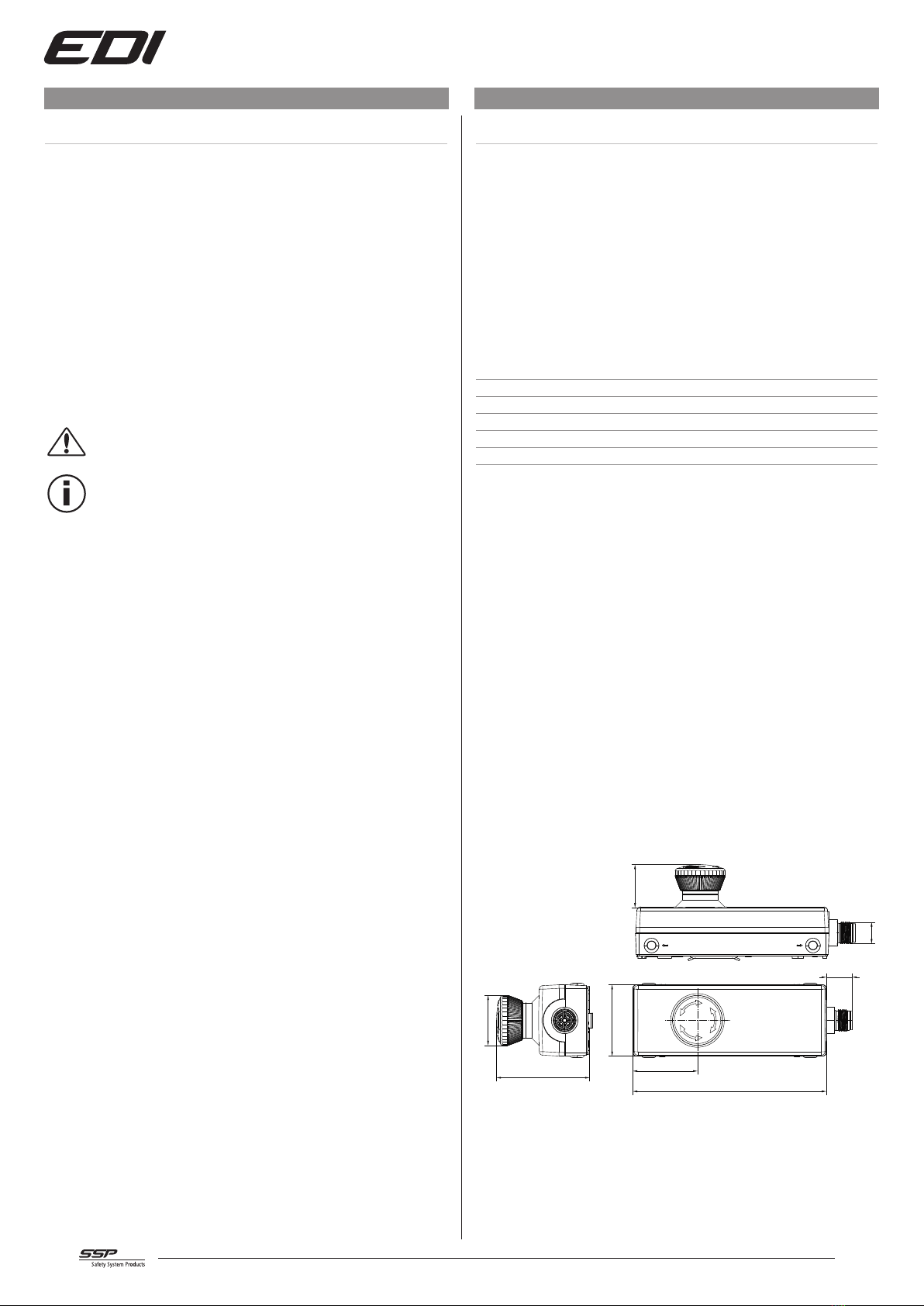
2.5 Dimensions
Dimensions in mm
108,6
40
36,3
14,6
24
M12
52,3
Ø28
EDI B7, EDI B7B

3
40
36
72
M12
20
14,5
52
Ø28
Ø28
EDI C7
36,3
108,6
14,6
40
36,3
Ø29
28,7
M12
EDI D1B
36
108,6
36
40
14,6
36,16
Ø29
28,6
M12
EDI E1B
2.6 Scope of Supply
• Emergency stop button in slimline housing and M12 plug connection
• Holding bracket
• EDI C7, D1B: Reset button, button cap & identification plate
• EDI E1B: Operating button, button cap red & green
2.7 Functions
• Confirm: Press the emergency stop button
• Unlock: Turn the emergency stop button
• Reset: Press the reset button (depending on the application)
• Two operating elements (depending on the application)
3. Installation
3.1 General installations notes
Make sure that emergency stop/emergency off button is mounted
at an easily accessible location.
The installation may only be carried out by authorized skilled personnel.
3.2 Installation of the build-in version EDI Slimline housing
The emergency stop button is intended for vertical or horizontal installation. Install the
emergency stop button as shown in the illustration.
• Tighten the holding bracket.
• Attach the housing to the side of the retaining spring, pull against the spring pressure
and press on the housing. The housing engages.
• Connect the M12 connection cable to the connector plug.
Wall installation Profile installation

4
4. Technical data
4.1 Switch elements
Item name EDI B7
SP-G-61-000-02
EDI B7B
SP-G-61-000-01
EDI C7
SP-G-61-000-04
EDI E1B
SP-G-61-000-05
EDI D1B
SP-G-61-000-09
Protection class (EN 60529) IP 65
Protection class (EN 61140) III
Operating ambient temperature –25 … +70°C
Storage temperature –25 … +80°C
Switch elements (EN 60947-5-1) 2 direct openings
2 direct openings
1 NO contact
Reset button
1 NO contact each 1 NO contact
Reset button
B10d value (EN ISO 13849-1) 250.000 switching cycles
MTTFd (mean time to failure, EN ISO 13849-1) 6849 (with switching frequency C = 1/d)
Electrical/mechanical service life (at +20°C)
Emergency stop buttons
Reset button
50.000 switching cycles (at rated load)
– 1 × 10⁶switching cycles 1 × 10⁶switching cycles
Max. bounce time < 10 mS
Min. direct opening path 3 mm
Data according to UL508
Utilisation category (EN 60947-5-1) DC13 DC13
Rated operating current Ie (EN 60947-5-1) 2 A 2 A
Rated operating voltage Ue 24 V DC (EN 60947-5-1) 24 V DC 24 V DC
Operating voltage 1 … 30 V DC 1 ... 36 V DC
Operating current 1 … 100 mA 1 ... 250 mA
Maximum switching capacity 250 mW
Housing material PBT (polybutylene terephthalate)
Contact material AgNi AgNi, gold plated 5 µm AgNi
Lighting connection emergency stop button
Operating voltage max 30V AC / DC
Operating current 4 mA (-24V AC)
Lighting connection reset button, operating button
Operating voltage max 30V AC / DC
Operating current 14 mA (at 24V DC)

5
5. Commissioning and Maintenance
5.1 Function Test
• Mechanical inspection:Emergency stop/emergency off button engages upon confirmation
• Electrical inspection: The machine stops or switches off upon confirmation of the
emergency stop/emergency off button.
Note
Damaged or defective devices must not be put into operation!
5.2 Periodic inspection
The inspection interval shall be determined by the machine designer on the basis of the risk
assessment. However, it is recommended that the emergency stop/emergency off button
is triggered at least once a year by the responsible safety officer for test purposes and to
check the correct function.
• mechanical and electrical function test in accordance with Step 5.1
• safe attachment
• manipulation and damage visible
• no loose wire connections
5.3 Behavior in the event of a malfunction
Note
Mechanical overload or external force can damage and impair the function of
the emergency stop button.
• Correct the error.
• Do a function test in accordance with Step 5.1.
6. Disassembly and Disposal
6.1 Removal
The EDI emergency stop/emergency off button must only be dismantled when the power
is disconnected.
6.2 Disposal
The EDI emergency stop/emergency off button must be disposed of properly in accordance
with national and local regulations.
7. Electrical connection
7.1 Pin assignment
Pin Assignment
EDI B7
1
4
3
2
1/2 NC contact 1 (emergen-
cy stop)
3/4 NC contact 2 (emergen-
cy stop)
EDI B7B
1
6
4
2
87
5
3
1/2 NC contact 1 (emergen-
cy stop)
3/4 NC contact 2 (emergen-
cy stop)
5 + LED (emergency stop)
6 - LED (emergency stop)
7/8 not assigned
EDI C7
1
6
4
2
87
5
3
1/2 NC contact 1 (emergen-
cy stop)
3/4 NC contact 2 (emergen-
cy stop)
5/6 Reset button
7 + LED reset button
8 - LED reset button
EDI E1B
1
4
3
2
1/2 NO contact
3/4 NC contact
EDI D1B
1
4
3
2
1/2x NO contact
3 + LED reset button
4 - LED reset button

6
8. Declaration of Conformity
8.1 EC conformity regulations
EDI emergency stop/emergency off button
Authorized representative: Johann Aulila
SSP Safety System Products GmbH & Co. KG
Max-Planck Str. 21, 78549 Spaichingen, Germany
www.safety-products.de
Date: October 2016
The designated products comply with the regulations of the directives:
• Machinery Directive 2006/42/EC
Applied standards:
• EN 60947-5-1: 2004
• EN 60947-5-5: 1997 + A1:2005 + A11:2013
• EN ISO 13850: 2015 (D)
Note
Signed EC Declaration of Conformity is available at the SSP website:
www.safety-products.de
SSP Safety System Products GmbH & Co. KG
Max-Planck-Straße 21
78549 Spaichingen, Germany
+49 7424 98 049-0
info@ssp.de.com
www.safety-products.de
This manual suits for next models
14
Table of contents
Other SSP Industrial Equipment manuals


