MAGUIRE Novatec AL-1 User manual

COMPRESSED
AIR LOADER
MODEL: AL-1
Document: AL-1 IM 10-22-2011

© 2011 Novatec Inc. All Rights Reserved
2
AL-1 IM 10-20-2011
Al-1 Compressed Air Loader Instructions
TABLE OF CONTENTS
Important Notices and Precautions 3
Quick Installation 4
Product Description 4
Principle of Operation 5
Unpacking and Inspection 5
Photoelectric Sensor Diagram 6
Installation 7
Operation 9
Maintenance 10
Troubleshooting 10
Spare Parts 11
Warranty 12

© 2011 Novatec Inc. All Rights Reserved
3
AL-1 IM 10-20-2011
Al-1 Compressed Air Loader Instructions
IMPORTANT NOTICE
Read this manual before operating equipment. Do not operate unless this instruction manual is
completely understood.
WARNING
Disconnect power and compressed air before servicing equipment. Only qualified technicians should
service equipment.
CAUTION
Check all mounts and connections to ensure that equipment is properly secured before operation. Only
qualified technicians should install and operate equipment.

© 2011 Novatec Inc. All Rights Reserved
4
AL-1 IM 10-20-2011
Al-1 Compressed Air Loader Instructions
QUICK INSTALLATION
1. Mount the chamber and filter/regulator with gauge assemblies.
2. Connect the material pick-up device.
3. Connect the compressed air.
4. Plug the power cord into a 115-volt outlet.
For full installation details, refer to the Installation section beginning on page 7.
PRODUCT DESCRIPTION
Novatec Model AL-1 loaders are automatic compressed air venturi loaders designed to convey virgin
pellets and regrind material from storage containers to drying hoppers or directly to process machines,
using compressed air.
The AL-1 is shipped complete, ready for quick set-up and use.
Novatec compressed air loaders only require a 14.0 SCFM @ 40 PSIG compressed air supply and 115
volt outlet for a typical operation.
The loader cyclone and sight glass are hopper or machine mounted with a single inlet, supplied with a
4” or 6” square blank mounting flange. The flange is normally supplied undrilled to allow the user to
drill the appropriate mounting pattern for a particular machine.
The AL-1 loader utilizes a “slip-fit” design for easy assembly. The receiving hopper slips into the sight
tube which in turn slides onto the mounting adapter; this process requires no tools and little time for
both installation and cleaning.

© 2011 Novatec Inc. All Rights Reserved
5
AL-1 IM 10-20-2011
Al-1 Compressed Air Loader Instructions
PRINCIPLE OF OPERATION
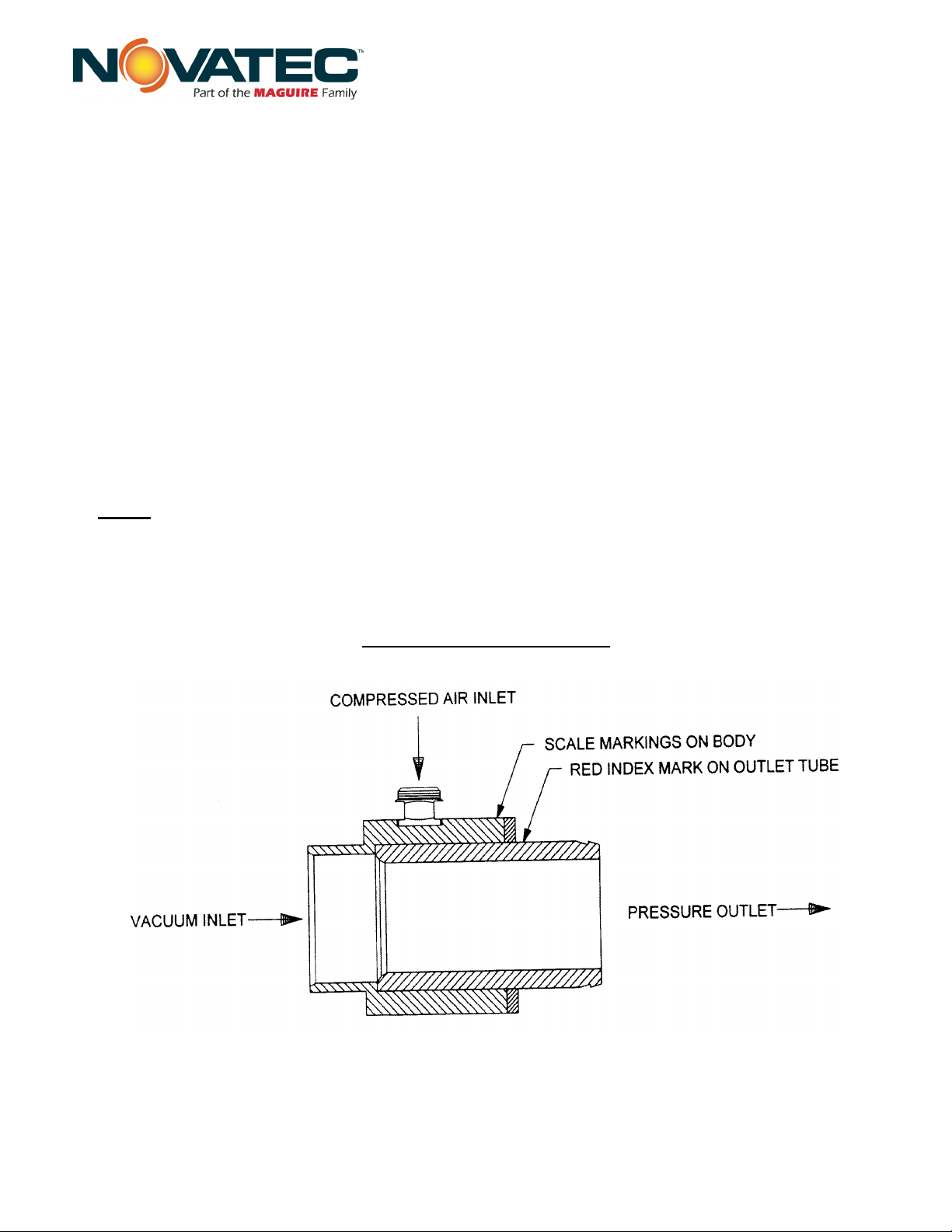
Novatec Model AL-1 loaders utilize compressed air in conjunction with an air amplifier to convey
material into a chamber. A small flow of compressed air passing through the amplifier creates a large
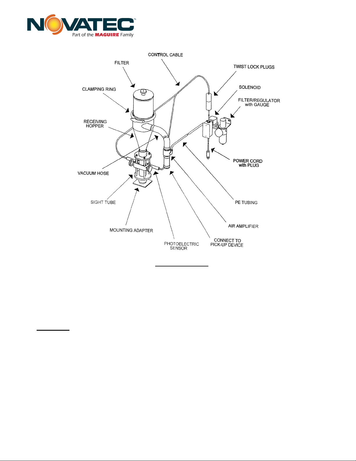
discharge flow by entraining the surrounding air. The machine or hopper mounted cyclone utilizes a
clear sight tube directly below it, and a photoelectric sensor consisting of an infrared light source and
an infrared sensor. See Figure 1 on next page for photoelectric sensor installation and configuration
details. The sensor controls loader on/off operation based upon the level of material within the sight
tube. Material is continuously drawn into the chamber as long as the dual photoelectric sensor
elements determine there is no material between them. The material level can be adjusted by sliding
the photoelectric sensor mount bracket up or down along the sight tube rods. Loading is discontinued
any time the material level within the sight tube reaches the sensor, and then is enabled again once the
material level drops. This process ensures a steady, consistent level of material.
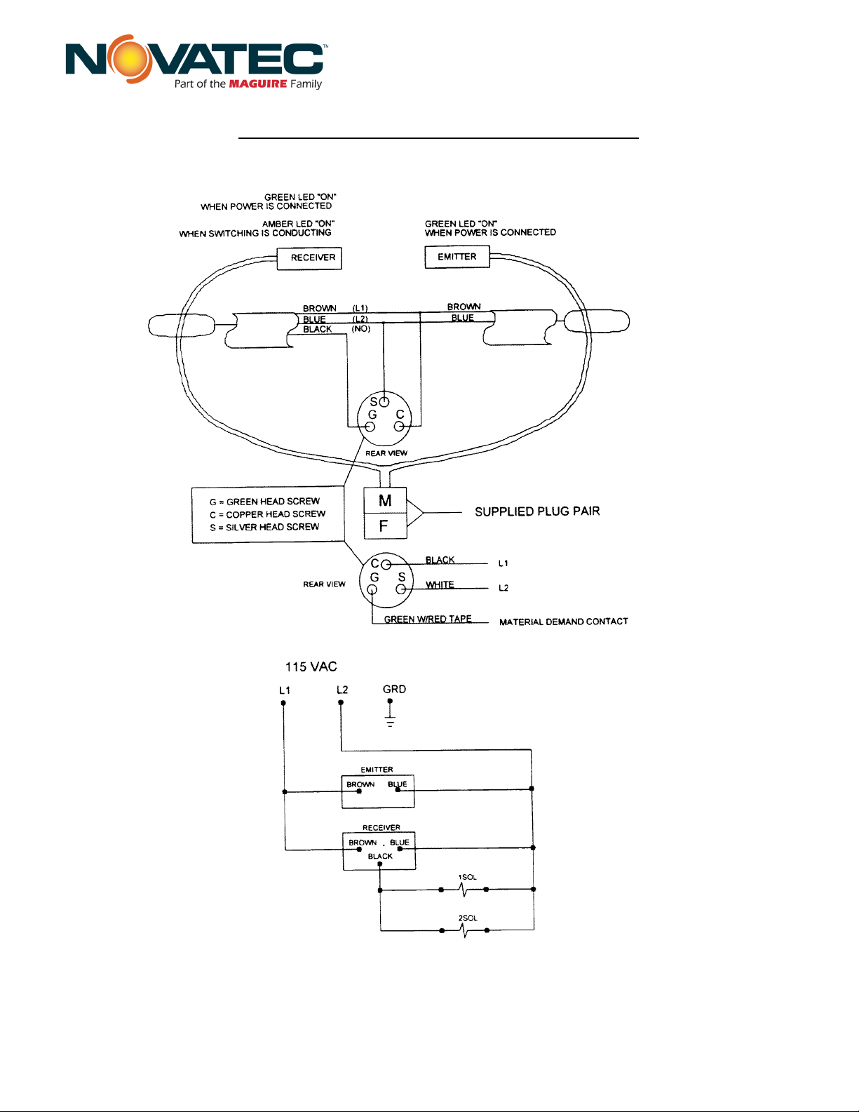
The loading operation is generated by a solenoid valve, which operates in response to the photoelectric
sensor. When material is present in the sight tube, the sensor de-energizes the solenoid valve, which
shuts off the compressed air and stops loading. Once the material level has dropped, the sensor
energizes the solenoid, allowing the compressed air to flow through the air amplifier.
Unlike capacitance types of sensors, dust build-up on the sight tube does not typically effect the
operation of the photoelectric sensor. The infrared beam of light will still pass through a layer of dust.
There are no sensitivity adjustments to be made to the sensor.
UNPACKING & INSPECTION
Caution should be exercised to see that the equipment is not handled roughly. The packaging must be
removed carefully. The equipment must not be used to pry against when removing the packaging.
Equipment is sent as completely assembled as possible so that there is little or no further attention
required prior to installation.
Once unpacked, visually inspect units for missing parts or damage received during shipment. All
electrical and mechanical connections should be checked for tightness, as vibration during transit may
cause them to loosen.

© 2011 Novatec Inc. All Rights Reserved
6
AL-1 IM 10-20-2011
Al-1 Compressed Air Loader Instructions
FIGURE 1 - PHOTOELECTRIC SENSOR DIAGRAM

© 2011 Novatec Inc. All Rights Reserved
7
AL-1 IM 10-20-2011
Al-1 Compressed Air Loader Instructions
INSTALLATION
Mount the loader so that the material inlet is directed towards the material pick-up point. Secure the
receiving hopper to ensure a safe installation as required. While mounting the receiving hopper,
adjustment of the photoelectric sensor can be done. The face of the sensor should be approximately
1/16” from the sight tube. Additionally, tighten down the filter hold-down knob and make sure the
clamping ring holding the filter is secure.
CAUTION:Do not over tighten the filter hold-down knob; excessive torque could damage the
filter element.
All connections should be vacuum tight. Use the 15 foot section of 1 1/2” OD vacuum hose to connect
the receiving hopper to the air amplifier and the 4 inch section to connect the air amplifier to the
material pick-up device; additionally, use the 3/8” OD PE tubing to connect the filter/regulator with
gauge assembly to the air amplifier. All lengths should be only as long as needed since excess hose
will reduce loader efficiency.

© 2011 Novatec Inc. All Rights Reserved
8
AL-1 IM 10-20-2011
Al-1 Compressed Air Loader Instructions
Check the air amplifier (see Figure 2, below) and ensure that the index is set at 6 (factory setting). The
index setting is marked with a red dot. The air amplifier setting should never need adjustment under
normal conditions.
The filter/regulator with gauge and junction box assembly should be mounted in a location that is
convenient for the operator, making sure that the position will take into consideration all limitations.
The filter/regulator with gauge assembly must interconnect with:
•a 115 volt supply outlet
•the twist lock plug connection for the photoelectric sensor
•the air amplifier for its compressed air connection
•the compressed air supply
Ensure that your compressed air is clean and dry; otherwise it will contaminate the material. If the unit
is used on a drying hopper, wet compressed air will cause a high dew point on the dryer. Connect the
filter/regulator to your compressed air supply.
NOTE: The compressed air supply must be 3/8” NPT, unrestricted line with a shut off valve.
Quick disconnects that restrict the flow of compressed air should not be used for this connection.
They are likely to create conveying problems.
FIGURE 2 - AIR AMPLIFIER

© 2011 Novatec Inc. All Rights Reserved
9
AL-1 IM 10-20-2011
Al-1 Compressed Air Loader Instructions
OPERATION
To begin operation, simply plug the power cord into a 115-volt outlet, turn on the compressed air
supply and adjust the regulator gauge to 60 PSI. This setting should provide a relatively good flow for
any material. The only adjustment that is needed once the unit is in operation is fine tuning the material
flow rate, using the filter/regulator with gauge if necessary. To disable the unit, simply unplug it.
Once in operation, fine-tune the adjustment until a smooth, consistent flow is obtained considering the
material characteristics, the distance from your material source and the ability of the system to easily
pickup and begin moving the material. If an adjustable pick-up device is being used, make sure the
device is set at the position where a smooth flow of material can be obtained.
Pull the knob on the regulator to adjust the compressed air setting. Turn the knob clockwise to increase
the pressure and counter-clockwise to decrease the pressure. Once the desired level is obtained, lock
the knob back in the place by pushing it down.
Observe the operation to assure it is consistent and responsive and that all components of the
installation are tight, dust free and secure.

© 2011 Novatec Inc. All Rights Reserved
10
AL-1 IM 10-20-2011
Al-1 Compressed Air Loader Instructions
MAINTENANCE
The filter element should be cleaned periodically by vacuuming or back flushing it with compressed
air.
TROUBLESHOOTING
If the AL-1 compressed air loader is not functioning correctly, the following items should be checked:
1. Check the filter. If the filter is dirty, it should be cleaned using a vacuum cleaner or compressed air.
If the filter is still dirty after cleaning or is damaged, the filter element should be replaced.
2. Ensure that all supply lines are connected. Check the power cord, compressed air supply, and the
twist lock plugs for proper operation.
3. Check the solenoid for proper operation.
4. Ensure all adjustable points are set correctly. Check the photoelectric sensor, regulator gauge, and
the air amplifier index for correct settings.
5. Check the entire system for leaks. Reconnect any material or compressed air lines, and replace any
gasket or sealant as necessary.
6. Check that the air amplifier index mark is set at 6.

© 2011 Novatec Inc. All Rights Reserved
11
AL-1 IM 10-20-2011
Al-1 Compressed Air Loader Instructions
SPARE PARTS LIST
ITEM DESCRIPTION
PART NUMBER
Cable, 18-3 SVO
08233
Cable, power cord w/ plug
08650
Hose Clamp, 1.50” OD
50049
Clamping Ring, 6.88” diameter
08883
Filter/regulator with gauge
08992
Cartridge Filter
07978
Silicone Gasket, 2.05” OD
08891
Vacuum Hose, 1.50” OD
50003
Knob, filter hold-down
08887
Knob, photo eye adjustment
07706
Photo eye Emitter
08343
Photo eye Receiver
08345
Tubing, 3/8” P.E.
08880
Sight Glass Tube, 2” OD
08894
Solenoid Valve, NC
50032
Twist Lock Plug, male
07542
Twist Lock Plug, female
07541

© 2011 Novatec Inc. All Rights Reserved
12
AL-1 IM 10-20-2011
Al-1 Compressed Air Loader Instructions
WARRANTY – NOVATEC, INC. -Effective Date 9-28-2011
NOVATEC, INC. offers COMPREHENSIVE PRODUCT WARRANTIES on all of our plastics auxiliary equipment. We
warrant each NOVATEC manufactured product to be free from defects in materials and workmanship, under normal
use and service for the periods listed under “Warranty Periods”. The obligation of Novatec, under this warranty, is
limited to repairing or furnishing, without charge, a similar part to replace any part which fails under normal use due to
a material or workmanship defect, within its respective warranty period. It is the purchaser’s responsibility to provide
Novatec with immediate written notice of any such suspected defect. Warranted replacement parts are billed and
shipped freight pre-paid. The purchaser must return the suspect defective part, freight prepaid and with identifying
documentation to receive full credit for the part returned. Novatec shall not be held liable for damages or delay caused
by defects. No allowance will be made for repairs or alterations without the written consent or approval of Novatec.
The provisions in equipment specifications are descriptive, unless expressly stated as warranties. The liability of
Novatec to the purchaser, except as to title, arising out of the supplying of the said equipment, or its use,
whether based upon warranty, contract or negligence, shall not in any case exceed the cost of correcting defects
in the equipment as herein provided. All such liability shall terminate upon the expiration of said warranty
periods. Novatec shall not in any event be held liable for any special, indirect or consequential damages.
Commodities not manufactured by Novatec are warranted and guaranteed to Novatec by the original
manufacturer and then only to the extent that Novatec is able to enforce such warranty or guaranty. Novatec,
Inc. has not authorized anyone to make any warranty or representation other than the warranty contained here.
Non-payment of invoice beyond 90 days will invalidate the warranty. A renewed warranty can be purchased
directly from Novatec.
Please note that we always strive to satisfy our customers in whatever manner is deemed most expedient to overcome
any issues in connection with our equipment.
Warranty Period:
Note: All warranty periods commence with the shipment of the equipment to the customer.
AL Series Loaders = 2 Years
Exclusions:
Routine maintenance/replacement parts are excluded from the warranty. These include, but are not limited to: hoses,
desiccant, filters, filter elements, wiper seals, gaskets, dew point sensors, infrared lamps, motors, internal solenoids,
fuses and motor brushes. Use with abrasive materials will void the warranty of any standard product. Wear resistant
options may be available to extend usable service life with abrasive materials. Novatec reserves the right to limit the
warranty if the customer installs replacement parts that do not meet the specifications of the original parts supplied by
Novatec.
*Specific Exclusions:
1. Nova Drier warranty is void if coalescing filters are not replaced on a 6-month or yearly basis (per instruction
manual) and/or membrane has been exposed to ozone.
2. NovaVac Dryer -The ability of the canisters to hold vacuum will be compromised if the vacuum seal edge is
damaged from mishandling. We do not warranty canisters damaged from improper handling. We do, however,
warranty the seals.
3. LOAD CELLS on our WSB’s are covered by Novatec standard warranty as long as they have not been damaged
from improper handling.
4. Velocity Control Valve warranty is voided if unit is placed in direct material flow.
This warranty shall not apply to equipment:
1. Repaired or altered without written approval of NOVATEC unless such repair or alteration was, in our judgment, not
responsible for the failure
2. Which has been subject to misuse, negligence, accident or incorrect wiring by others
3. Warranty is void if processing rates exceed manufacturer-recommended levels or if damage is caused by ineffective
power isolation and/or power spikes/sags or incorrect installation.
NOTE: All conditions and content of this warranty are subject to changes without notice.
Table of contents
Other MAGUIRE Industrial Equipment manuals
Popular Industrial Equipment manuals by other brands

woodmizer
woodmizer TVS-FT Series user manual

Delta
Delta HEX110QA Specification and Manual

Gema
Gema UA05 operating instructions

Sherman + Reilly
Sherman + Reilly PTR-7230 Operator's manual

HunterDouglas
HunterDouglas Luxalon 75C Installation instruction

Ice Qube
Ice Qube IQ700HE Operation and installation manual

Premier Manufacturing Co.
Premier Manufacturing Co. 1400 COUPLING Installation, Inspection, Operation & Maintenance Guide

Self Climat
Self Climat DN 50 Fitting and operating instructions

Unitrol
Unitrol PO-22 instruction manual

Entrematic
Entrematic Ditec VALHLLOK installation manual

Delta
Delta HEX080PD Series instruction manual

Cold Jet
Cold Jet IceTech R1000H user manual