MAHA MLT Series User manual

Fehler! Verwenden Sie die Registerkarte 'Start', um Name dem Text zuzuweisen, der hier angezeigt werden soll.Fehler! Verwenden Sie
die Registerkarte 'Start', um Name dem Text zuzuweisen, der hier angezeigt werden soll.Fehler! Verwenden Sie die Registerkarte
'Start', um Name dem Text zuzuweisen, der hier angezeigt werden soll.
MLT 3000
Headlight Tester
Original Operating Instructions
BA380701-en
Pos: 1 /Produktfamilien/Scheinwerferprüftechnik/MLT-SERIES/380701 MLT 3000/BA/Inha lt: 3807 Titelbild @ 55\mod_1552900817069 _0.docx @ 3126274 @ @ 1
Pos: 2 /-----Fo rmat-----/Se itenumbruch@ 0\mod_1134403577687_0.do cx @ 1277@ @ 1

2
BA380701-en
Pos: 3 /Produktfamilien/Alle Geräte/Inhalte/Inhalt: Firmen-Info rmation MAHA 2019 @ 56\mod_1557818397795_75. docx @ 3141940 @ @ 1
BA380701-en
2018-11-20
© MAHA Maschinenbau Haldenwang GmbH & Co. KG
The reproduction, distribution and utilization of this document as well as the communication of its
contents to others without explicit authorization is prohibited. Offenders will be held liable for the
payment of damages. All rights reserved in the event of the grant of a patent, utility model or de-
sign. The contents of this edition have been checked with great care. However, errors cannot be
fully excluded. Subject to technical change without notice.
Manufacturer
MAHA Maschinenbau Haldenwang GmbH & Co. KG
Hoyen 20
87490 Haldenwang
Germany
Phone: +49 8374 585 0
Fax: +49 8374 585 590
Mail: maha@maha.de
Web: www.maha.de
Service
MAHA SERVICE CENTER
Maybachstraße 8
87437 Kempten
Germany
Phone: +49 8374 585 100
Fax: +49 8374 585 491
Mail: service@maha.de
Web: www.mahaservicecenter.de
Pos: 4 /-----Fo rmat-----/Se itenumbruch@ 0\mod_1134403577687_0.do cx @ 1277 @ @ 1

3
BA380701-en
Pos: 5 /-----Fo rmat-----/Inha ltsverzeichnis - 3Ebenen @ 5\mod_1168867441046_75.do cx @ 72920 @ @ 1
Contents
1
Safety ....................................................................................................................5
1.1 Introduction..............................................................................................................5
1.2 Symbols and Signal Words ......................................................................................5
1.2.1 Personal Injury..........................................................................................................5
1.2.2 Property Damage.....................................................................................................5
1.2.3 Information...............................................................................................................5
1.3 Intended Use ...........................................................................................................6
1.4 Requirements on Operating and Service Personnel ..................................................6
1.5 Safety Instructions....................................................................................................6
2
Description ............................................................................................................7
2.1 Requirements for the Place of Installation .................................................................7
2.2 Specifications...........................................................................................................7
2.3 Design .....................................................................................................................8
2.4 Electronic Levelling...................................................................................................9
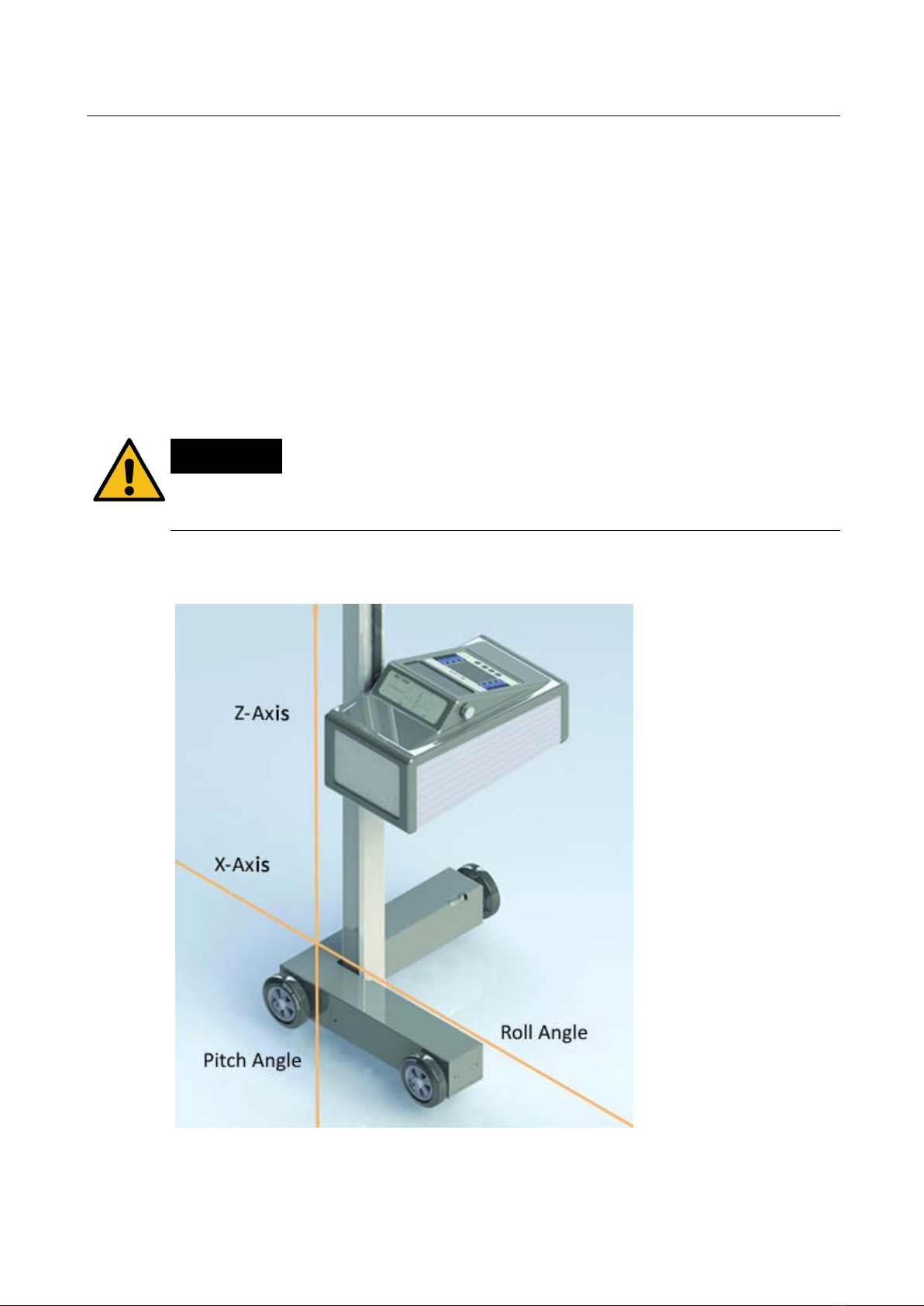
2.4.1 Compensation Coordinate Axes of MLT 3000 ..........................................................9
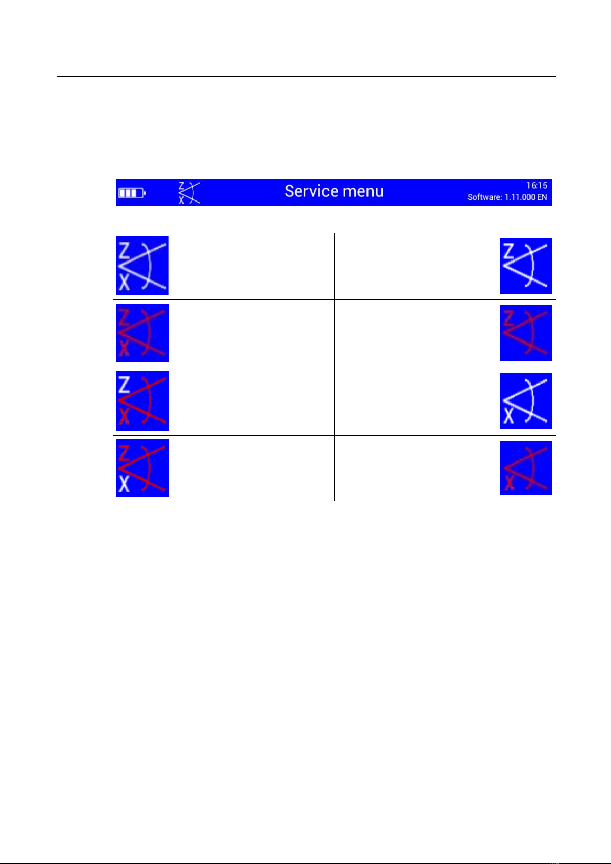
2.4.2 Angle Symbols .......................................................................................................10
2.5 Definition of Technical Terms..................................................................................11
2.5.1 Pitch Angle.............................................................................................................11
2.5.2 Low Beam .............................................................................................................11
2.5.3 High Beam.............................................................................................................12
3
Operation.............................................................................................................13
3.1 Switching On / Off..................................................................................................13
3.2 Aligning..................................................................................................................14
3.2.1 Laser Alignment Unit (Option) .................................................................................14
3.2.2 LED Adjustment Aid (Option) ..................................................................................15
3.3 Light Selection Buttons ..........................................................................................16
3.3.1 Headlight Test according to § 29 StVZO (Germany)................................................16
3.3.2 Showing the Button Labels ....................................................................................17
3.3.3 Adjusting the Pitch Angle........................................................................................17
3.3.4 Choosing the Vehicle Class ....................................................................................18
3.3.5 Browsing back through the Test Screens ...............................................................18
3.3.6 Choosing between Left-Hand or Right Hand Traffic................................................19
3.3.7 Manufacturer-Specific Test Instructions (OEM) .......................................................19
3.3.8 Navigating through the Test Levels.........................................................................21
3.4 Testing the Headlights............................................................................................22

4
BA380701-en
3.4.1 Test Phase Indication via Light Buttons ..................................................................22
3.4.2 Measuring..............................................................................................................22
3.4.3 Light Selection Buttons Disabled ............................................................................23
3.4.4 Adjusting: Setting the Headlights in Real Time ........................................................24
3.4.5 Saving the Measurement Values to PDF.................................................................25
3.5 Settings .................................................................................................................27
3.5.1 Variables ................................................................................................................27
3.5.2 User Settings .........................................................................................................29
3.5.3 Language...............................................................................................................30
3.5.4 Calibrating the Camera according to Directive ........................................................31
3.5.5 Country Specifications............................................................................................33
3.5.6 Settings with Password..........................................................................................34
3.5.7 List of Variables (Extract) ........................................................................................35
3.6 Interfaces and Software Updates ...........................................................................36
3.7 EUROSYSTEM v7.50.............................................................................................38
4
Energy Management and Troubleshooting ............................................................41
4.1 Charging the Battery ..............................................................................................41
4.2 Battery Status ........................................................................................................42
4.2.1 Battery Life.............................................................................................................42
4.2.2 Energy Saving Function..........................................................................................42
4.2.3 Protection against Deep Discharge.........................................................................42
4.2.4 Protection against Mechanical Damage..................................................................42
4.2.5 Data Recording for Error Analysis ...........................................................................43
4.3 Troubleshooting .....................................................................................................44
5
Maintenance ........................................................................................................44
5.1 Care Instructions....................................................................................................44
5.2 Spare Parts............................................................................................................44
6
Disposal............................................................................................................... 45
7
Contents of the Declaration of Conformity.............................................................45
Pos: 6 /-----Fo rmat-----/Se itenumbruch@ 0\mod_1134403577687_0.do cx @ 1277 @ @ 1

5
BA380701-en
Pos: 7 /Produktfamilien/Alle Geräte/Überschriften/Überschriften1/S/Überschrift1: Sicherheit@ 6\mod_117448239 9906_75.docx @ 76962 @ 1 @ 1
1
Safety
Pos: 8 /Produktfamilien/Alle Geräte/Überschriften/Überschriften 1.1/E/Überschrift 1.1: Einführung @ 6\mod_ 1174482219062_75.d ocx @ 76793 @ 1@ 1
1.1
Introduction
Pos: 9 /Produktfamilien/Alle Geräte/Inhalte/Sicherheit/Inhalt: Einführung Sicherheit_12pt @ 25\mod_1324455248318_ 75.docx @ 1138886 @ @ 1
Thoroughly read this manual before operating the equipment and comply with the
instructions. Always display the manual in a conspicuous location.
Personal injury and property damage incurred due to non-compliance with these
safety instructions are not covered by the product liability regulations.
Pos: 10.1 /Produktfamilien/Alle Geräte/Überschriften/Überschriften 1.1/S/Überschrift 1.1: S ymbole und Signalwörter @ 50\mod_ 1503314612825_75.docx @ 2923200 @ 2 @ 1
1.2
Symbols and Signal Words
Pos: 10.2/Produktfamilien/AlleGeräte/Überschriften/Überschriften1.1.1/P/Überschrift1.1.1: Personenschäden@ 50\mod_ 1503389040316_75. docx @ 29 23708 @ 3 @ 1
1.2.1
Personal Injury
Pos: 10.3 /Produktfamilien/Alle Geräte/Inhalte/Sicherheit/Inhalt: Symbole und Signalwörter - Personenschäden@ 50\mod_150338942747 0_75.docx @ 2923852 @ @ 1
DANGER
indicates an immediate hazard which, if not avoided, will result in death or severe
personal injury.
WARNING
indicates a potential hazard which, if not avoided, could result in death or severe
personal injury.
CAUTION
indicates a potential hazard which, if not avoided, could result in moderate or mi-
nor personal injury.
Pos: 10.4 /Produktfamilien/Alle Geräte/Überschriften/Überschriften 1.1.1/P/Überschrift 1.1.1: Produkt-, Maschinen-, Anlagenschäden@ 50\mod_1503389109661_75. docx @ 2923756 @ 3 @ 1
1.2.2
Property Damage
Pos: 10.5 /Produktfamilien/Alle Geräte/Inhalte/Sicherheit/Inhalt: Symbole und Signalwörter - P roduktschäden@ 50\mod_1503389546628_75.d ocx@ 29 23899@ @ 1
NOTICE
indicates a potentially harmful situation which, if not avoided, could result in dam-
age to the equipment or surrounding objects.
Pos: 10.6 /Produktfamilien/AlleGeräte/Überschriften/Überschriften 1.1.1/I/Überschrift 1.1.1: Informationen @50\mod_ 1503389229939_75.docx @ 2923804 @ 3 @ 1
1.2.3
Information
Pos: 10.7 /Produktfamilien/Alle Geräte/Inhalte/Sicherheit/Inhalt:Symbole und Signalwörter- Informationen @ 56\mod_ 1560326812841_75.doc x @ 3147455 @ @ 1
indicates important information notes.
Pos: 11 /-----Fo rmat-----/ Seitenumbruch @ 0\mod_113440357768 7_0.docx @ 1277 @ @ 1

6
BA380701-en
Pos: 12/Produktfamilien/AlleGeräte/Überschriften/Überschriften1.1/B/Überschrift1.1: BestimmungsgemäßerGebrauch @ 6\mod_1176734022203_75.do cx@ 88746 @ 2 @ 1
1.3
Intended Use
Pos: 13 /Produktfamilien/Scheinwerferprüftechnik/MLT-SERIES/380701 MLT3000/ BA/Inhalt: 3807 Best immungsgemäßer Gebra uch_12pt @ 26\mod_1325493887453_ 75.docx @ 1142050 @ @ 1
This device only serves to check and adjust the alignment of vehicle headlights.
This device cannot be modified without the express, written consent of the
manufacturer. Any infringement renders the conformity declaration invalid.
Pos: 14 /Produktfamilien/AlleGeräte/Überschriften/Überschriften 1.1/A/Überschrift 1.1: Anforderungen andas Bedienungs- undServicepersonal @ 34\mod_1380637 497630_75.do cx @1835413 @ 2 @ 1
1.4
Requirements on Operating and Service Personnel
Pos: 15 /Produktfamilien/AlleGeräte/Inhalte/Sicherheit/Inhalt: WARNUNG - Anforderungen an das Bedienungs- und Serviceperso nal_12pt @ 52\mod_ 1516807277486_75.docx @ 3001475 @ @ 1
WARNING
All persons employed in the operation, maintenance, installation, removal and dis-
posal of the device must
•be at least 18 years old,
•be mentally and physically suited for these activities,
•be demonstrably trained and instructed in writing,
•have read and understood the operating instructions, especially the instructions
what to do in the event of defects or malfunctions,
•be on record as having been instructed in safety guidelines,
•have practical experience in working with vehicle lifts and the hazards inherent
in such equipment.
Pos: 16 /Produktfamilien/AlleGeräte/Überschriften/Überschriften 1.1/S/Überschrift 1.1: Sicherheitsvorschriften @8\mod_ 1204545563175_75.d ocx @ 155576 @ 2@ 1
1.5
Safety Instructions
Pos: 17 /Produktfamilien/Scheinwerferprüftechnik/MLT-SERIES/380701 MLT3000/ BA/Inhalt: 3807 Sic herheitsvorsch riften @ 54\mod_1532346009263_75. docx @ 3052006 @ @ 1
NOTICE
•This device must only ever be operated within its performance limits.
•All parts of the electrical system must be protected against damp and humidity.
•All service work must be performed by service technicians employed by the
manufacturer or by authorized service partners.
•Never expose the lens to direct sunlight. The bundling of light may cause fire
damage inside the housing.
•Only ever clean the lens with a soft cloth and a glass cleaning agent.
CAUTION
Optional laser alignment unit: Never look into the laser beam (laser class 2M).
Comply with work safety and accident prevention directives (H&SW regulations) in
respect of laser radiation.
Pos: 18 /-----Fo rmat-----/ Seitenumbruch @ 0\mod_113440357768 7_0.docx @ 1277 @ @ 1

7
BA380701-en
Pos: 19 /Produktfamilien/Alle Geräte/Überschriften/Überschriften 1/B/Überschrift1: Beschreibung@ 6\mod_11744822 71453_75.do cx @ 76889 @ 1@ 1
2
Description
Pos: 20 /Produktfamilien/Alle Geräte/Überschriften/Überschriften1.1/A/Überschrift1.1: Anforderungenan den Aufstellort@ 7\mod_ 1184077643671_75.docx @ 99737 @ 1 @ 1
2.1
Requirements for the Place of Installation
Pos: 21 /Produktfamilien/Scheinwerferprüftechnik/MLT-SERIES/380701 MLT3000/ BA/Inhalt: 3807 Anforderunge n an den Aufste llort @ 54\mod_153621249 3413_75.docx @ 3086120 @ @ 1
Please observe your national guidelines and specifications.
Pos: 22 /Produktfamilien/AlleGeräte/Überschriften/Überschriften 1.1/T/Überschrift 1.1: Technische Daten@ 7\mod_11840755 26343_75.do cx @ 99711 @ 1 @ 1
2.2
Specifications
Pos: 23 /Produktfamilien/Scheinwerferprüftechnik/MLT-SERIES/380701 MLT3000/ BA/Inhalt: 3807 Tech nische Daten @ 54\mod_15361459 09641_75.docx @ 3085972 @ @ 1
Measuring range above hotspot 0…800 mm / 10 m (0…8 %)
a
b
ove pitch angle 0…300 mm / 10 m (0…3 %)
below 0…700 mm / 10 m (0…7 %)
left 0…1000 mm / 10 m (0…10 %)
right 0…1000 mm / 10 m (0…10 %)
Light intensity 0…125 000 cd
Illuminance 0…200 lx
Measuring distance 100…500 mm
Adjustment path of lens centre above floor 240…1500 mm
Deviation of intensity ±5 %
Deviation from one axle ±5'
Compensation of ground unevenness ±3 %
Temperature +5…+40 °C
Relative humidity 20…80 %
Supply voltage 100…240 V AC, 50/60 Hz
Charging voltage / Battery voltage 24 V DC / 12 V DC
Dimensions (W x H x D) 655 x 1770 x 720 mm
Net weight / Shipping weight 65 kg / 80 kg
Prototype release number TPN100110935
Pos: 24 /-----F orma t-----/Seitenumbruch @ 0\mod_11344035 77687_0.doc x @ 1277 @ @ 1

8
BA380701-en
Pos: 25 /Produktfamilien/AlleGeräte/Überschriften/Überschriften 1.1/A/Überschrift 1.1: Aufbau@ 12\mod_1232632872281_75.do cx @ 319982@ 2 @ 1
2.3
Design
Pos: 26 /Produktfamilien/Scheinwerferprüftechnik/MLT-SERIES/380701 MLT 3000/BA/Inhalt :3807 A ufbau (Bilder) @ 54\mod_ 1536150020420_0.do cx @ 3086046 @ @ 1
Pos: 27 /Produktfamilien/Scheinwerferprüftechnik/MLT-SERIES/380701 MLT3000/ BA/Inhalt: 3807 Aufb au (Legende) @ 54\mod_1536149 532463_75.doc x@ 3086009 @ @ 1
A
Mirror, with optional
laser alignment unit
E
Charging socket
B
Column
F
Casing, with adjusting handle
C
Display
G
Carriage, with spirit level
D
USB port
H
Battery compartment
Pos: 28 /-----Fo rmat-----/ Seitenumbruch @ 0\mod_113440357768 7_0.docx @ 1277 @ @ 1
A
B
D
G
H
C
E
F

9
BA380701-en
Pos: 29 /Produktfamilien/Alle Geräte/Überschriften/Überschriften 1.1/E/Überschrift 1.1: Elektronischer Niveauausgleich@ 41\mod_1417423524511_ 75.docx @ 2159642 @ 2@ 1
2.4
Electronic Levelling
Pos: 30 /Produktfamilien/Scheinwerferprüftechnik/MLT-SERIES/380701 MLT3000/ BA/Inhalt: 3807 Elek tronischer Nive auausgleich (Text) @ 54\mod_ 1531120422247_75.d ocx @ 3043575 @ @ 1
This headlight tester comes standard with an electronic position sensor which
determines the inclination angle of the device. The software compensates possible
deviations in the X- and Z-axes while calculating the position of the headlights.
The headlight tester may be set up on uneven surfaces even if the ground
unevenness is outside the permissible tolerances, provided that the maximum
unevenness does not exceed the headlight tester’s self-levelling capacity of 3%.
After enabling the respective function, the compensation values can be checked
using a dot or cross hair laser. See section “Operation > Settings > Calibrating the
Camera according to Directive”.
NOTICE
This function must be enabled exclusively by authorised service technicians and is
applicable for the respective test surface only.
Pos: 31 /Produktfamilien/AlleGeräte/Überschriften/Überschriften 1.1.1/K/Überschrift 1.1.1: Kompensations-Koordinatenach sen MLT 3000 @ 55\mod_1542017762248_75. docx @ 309 6930 @ 3 @ 1
2.4.1
Compensation Coordinate Axes of MLT 3000
Pos: 32 /Produktfamilien/Scheinwerferprüftechnik/MLT-SERIES/380701 MLT3000/ BA/Inhalt: 3807 Ko ordinatenachsen @ 55\mod_ 1542018248398_75.docx @ 3096968 @ @ 1
Pos: 33 /-----Fo rmat-----/ Seitenumbruch @ 0\mod_113440357768 7_0.docx @ 1277 @ @ 1

10
BA380701-en
Pos: 34 /Produktfamilien/Alle Geräte/Überschriften/Überschriften 1.1.1/W/Überschrift 1.1.1: Winkelsymbole @ 54\mod_1536136536153_ 75.docx @ 3085897 @ 3@ 1
2.4.2
Angle Symbols
Pos: 35 /Produktfamilien/Scheinwerferprüftechnik/MLT-SERIES/380701 MLT 3000/BA/Inhalt :3807 Wi nkelsymbole @ 54\mod_ 1536138559566_75.doc x@ 3085935 @ @ 1
Once the adjustment of the inclination sensor has been completed, an angle sym-
bol appears in the info bar to indicate the adjusted/active inclination axes.
Overview of symbols:
Both axes adjusted/active,
headlight tester ready for
operation
Z-axis active, headlight test-
er ready for operation
Both axes active, inclination
of Z- and X-axis too large,
no measurement possible
Z-
axis active, inclination too
large, no measurement pos-
sible
Both axes active, inclination
of X-axis too large, no
measurement possible
X-axis active, headlight test-
er ready for operation
Both axes active, inclination
of Z-axis too large, no
measurement possible
X-
axis active, inclination too
large, no measurement pos-
sible
Pos: 36 /-----Fo rmat-----/ Seitenumbruch @ 0\mod_113440357768 7_0.docx @ 1277 @ @ 1

11
BA380701-en
Pos: 37 /Produktfamilien/Alle Geräte/Überschriften/Überschriften 1.1/B/Überschrift 1.1: Begriffsbestimmung @ 21\mod_12833387117 24_75.docx @ 884333 @ 2 @ 1
2.5
Definition of Technical Terms
Pos: 38 /Produktfamilien/AlleGeräte/Überschriften/Überschriften 1.1.1/N/Überschrift 1.1.1: Nickwinkel@ 25\mod_1319632959141_ 75.docx @ 1067583 @ 2 @ 1
2.5.1
Pitch Angle
Pos: 39 /Produktfamilien/Scheinwerferprüftechnik/-Arc hiv -/38 Scheinwerfer-Einstell-Prüfgeräte/0501 LITE 3/BA/Inhalt: 3805 Beg riffsbestimmungNickwinkel (Bild) @ 21\mod_1283343123850_0.do cx @ 884364 @ @ 1
Pos: 40 /Produktfamilien/Scheinwerferprüftechnik/-Arc hiv -/38 Scheinwerfer-Einstell-Prüfgeräte/0501 LITE3/BA/ Inhalt: 3805 Be griffsbestimmung Nickwinkel (Te xt) @ 26\mod_132549 5352529_75.docx @ 1142312 @ @ 1
Angle of inclination of light-dark limit against the test surface.
The inclination of headlight lighting bundle against the test surface is expressed as
a percentage, using 10 m as a reference parameter:
X 100
Pos: 41 /Produktfamilien/Alle Geräte/Überschriften/Überschriften 1.1.1/A/Überschrift 1.1.1: Abblendlicht @ 25\mod_ 1319633029481_75.doc x@ 1067613 @ 2 @ 1
2.5.2
Low Beam
Pos: 42 /Produktfamilien/Scheinwerferprüftechnik/-Arc hiv -/38 Scheinwerfer-Einstell-Prüfgeräte/0501 LITE 3/BA/Inhalt: 3805 Beg riffsbestimmungAbble ndlicht(Bild) @ 25\mod_1319631975821_0. docx@ 1067463 @ @ 1
Pos: 43 /-----Fo rmat-----/ Seitenumbruch @ 0\mod_113440357768 7_0.docx @ 1277 @ @ 1

12
BA380701-en
Pos: 44 /Produktfamilien/Scheinwerferprüftechnik/-Arc hiv -/38 Scheinwerfer-Einstell-Prüfgeräte/0501 LITE 3/BA/Inhalt: 3805 Begriffsbestimmung Abblendlicht ( Text) @ 26\mod_132549 5443262_75.docx @ 1142344 @ @ 1
A
Light-dark limit
Boundary for light distribution between ‘top dark’ and ‘bottom light’ for low-
beam lights.
B
Inflection point
Synonymous with the light-dark limit for asymmetric low-beam lighting. The
deviation of the inflection point is expressed in %. 10 meters is used as the
reference dimension.
α
Yaw angle
Angle between the inflection point on the rising component of the light-dark
limit and the horizontal line for asymmetric low-beam light.
α
Rolling angle
Angle between the left component of the light-dark limit and the horizontal,
usually 0°.
Pos: 45 /Produktfamilien/Alle Geräte/Überschriften/Überschriften 1.1.1/F/Überschrift 1.1.1: Fernlicht @ 25\mod_1319 633186648_75.doc x@ 1067673 @ 3 @ 1
2.5.3
High Beam
Pos: 46 /Produktfamilien/Scheinwerferprüftechnik/-Arc hiv -/38 Scheinwerfer-Einstell-Prüfgeräte/0501 LITE3/BA/ Inhalt: 3805 Begriffsbestimmung Fernlicht (Bild) @ 25\mod_ 1319632161039_0.docx @ 1067493 @ @ 1
Pos: 47 /Produktfamilien/Scheinwerferprüftechnik/-Arc hiv -/38 Scheinwerfer-Einstell-Prüfgeräte/0501 LITE 3/BA/Inhalt: 3805 Beg riffsbestimmungFernlicht (Text) @ 26\mod_1325495528426_75.d ocx @ 1142376@ @ 1
C
Central mark
From the central mark, the deviation of hot-spot is specified in X and Y di-
rections.
D
Hot spot
Center of light beam for high-beam. The deviation of hot spot from central
mark is expressed in %.10 meters is used as the reference dimension.
Pos: 48 /-----Fo rmat-----/ Seitenumbruch @ 0\mod_113440357768 7_0.docx @ 1277 @ @ 1

13
BA380701-en
Pos: 49 /Produktfamilien/Alle Geräte/Überschriften/Überschriften 1/B/Überschrift1: Bedienung@ 6\mod_1174482 271218_75.do cx@ 76877 @ 3 @ 1
3
Operation
Pos: 50 /Produktfamilien/Alle Geräte/Überschriften/Überschriften 1.1/E/Überschrift 1.1: Einschalten / Ausscha lten@ 20\mod_1271841463134_75. docx@ 838371 @ 3 @ 1
3.1
Switching On / Off
Pos: 51 /Produktfamilien/Scheinwerferprüftechnik/MLT-SERIES/380701 MLT 3000/BA/Inhalt :3807 E in-/Ausschalten @ 54\mod_153112136144 7_75.docx @ 3043622 @ @ 1
The headlight tester is operated via touchscreen buttons. The resistive touch-
screen reacts to pressure and can also be operated while wearing work gloves.
The On/Off button is on the right-hand side underneath the touchscreen.
Press to confirm Switch Off.
Pos: 52 /-----Fo rmat-----/ Seitenumbruch @ 0\mod_113440357768 7_0.docx @ 1277 @ @ 1

14
BA380701-en
Pos: 53 /Produktfamilien/AlleGeräte/Überschriften/Überschriften 1.1/A/Überschrift 1.1: Ausrichten @ 21\mod_1283344889785_75.doc x@ 884424 @ 1 @ 1
3.2
Aligning
Pos: 54 /Produktfamilien/Scheinwerferprüftechnik/MLT-SERIES/380701 MLT3000/ BA/Inhalt: 3807 Ausr ichten Standard (Tex t) @ 55\mod_1542026006515_75.d ocx @ 3097275 @ @ 1
When using guide rails, position the device centrally in front of the vehicle.
Without guide rails, the device must be adjusted in front of each headlight. Please
observe your national guidelines and specifications.
The device is correctly aligned when two symmetrical reference points on the front
of the vehicle are located on the black line of the alignment mirror.
Pos: 55 /Produktfamilien/Scheinwerferprüftechnik/MLT-SERIES/380701 MLT3000/ BA/Inhalt: 3807 Ausr ichten Standard (Bil d) @ 55\mod_1542025471657_0.d ocx @ 3097162 @ @ 1
Pos: 56 /Produktfamilien/Alle Geräte/Überschriften/Überschriften 1.1.1/L/Überschrift 1.1.1: Laser-Ausrichteinheit (Option) @ 55\mod_15420257189 69_75.docx @ 309 7199 @ 3 @ 1
3.2.1
Laser Alignment Unit (Option)
Pos: 57 /Produktfamilien/Scheinwerferprüftechnik/MLT-SERIES/380701 MLT3000/ BA/Inhalt: 3807 Lase r-Ausrichteinheit (Text) @ 55\mod_1542024633290_ 75.docx @ 3097125 @ @ 1
The optional unit is integrated into the mirror holder. The device is correctly aligned
when the laser pointer is parallel to two symmetrical reference points on the front
of the vehicle.
Observe manufacturer’s instructions according to workshop manual.
CAUTION
Never look into the laser beam (laser class 2M). Comply with work safety and ac-
cident prevention directives (H&SW regulations) in respect of laser radiation.
The AA Mignon batteries powering the laser are located in the alignment unit and
can be easily replaced.
Pos: 58 /Produktfamilien/Scheinwerferprüftechnik/MLT-SERIES/380701 MLT3000/ BA/Inhalt: 3807 Lase r-Ausrichteinheit (Bild) @ 55\mod_1542026341536_ 0.docx @ 3097312 @ @ 1

15
BA380701-en
Pos: 59 /Produktfamilien/Alle Geräte/Überschriften/Überschriften1.1.1/L/Überschrift1.1.1: LED-Justagehilfe(Option) @ 55\mod_1542025822583_75.d ocx @309 7237@ 3 @ 1
3.2.2
LED Adjustment Aid (Option)
Pos: 60 /Produktfamilien/Scheinwerferprüftechnik/MLT-SERIES/380701 MLT3000/ BA/Inhalt: 3807 LED -Justagehilfe (Text) @ 55\mod_1542026638860_75. docx @ 3097349 @ @ 1
This optional unit is integrated into the window housing (A) above the Fresnel lens.
The colour LEDs (B) pointing toward the vehicle indicate the direction of adjust-
ment.
Green LED = Optimum setting
(corresponds to green rating in the display centre)
Yellow LED = Minor deviation within tolerance range
(corresponds to yellow direction arrows on the display)
Red LED = Outside tolerance
(corresponds to red direction arrows on the display)
Pos: 61 /Produktfamilien/Scheinwerferprüftechnik/MLT-SERIES/380701 MLT3000/ BA/Inhalt: 3807 LED -Justagehilfe (Bilder) @ 55\mod_154202719289 9_0.docx @ 3097386 @ @ 1
Pos: 62 /-----Fo rmat-----/ Seitenumbruch @ 0\mod_113440357768 7_0.docx @ 1277 @ @ 1
A
B

16
BA380701-en
Pos: 63 /Produktfamilien/Alle Geräte/Überschriften/Überschriften 1.1/L/Überschrift 1.1: Lichtauswahltasten @ 34\mod_ 1380638042998_75.doc x @ 1835457 @ 2 @ 1
3.3
Light Selection Buttons
Pos: 64 /Produktfamilien/Scheinwerferprüftechnik/MLT-SERIES/380701 MLT3000/ BA/Inhalt: 3807 Lich tauswahltasten @ 54\mod_ 1531122680567_75.do cx@ 3043669 @ 33333333 @ 1
3.3.1
Headlight Test according to § 29 StVZO (Germany)
Headlight test according to § 29 StVZO (Germany).
Use the OEM button for manufacturer-specific test instructions.

17
BA380701-en
3.3.2
Showing the Button Labels
When the Info button is activated, the button labels are shown instead of the
symbols.
3.3.3
Adjusting the Pitch Angle
The pitch angle can be increased or reduced using the Arrow buttons.

18
BA380701-en
3.3.4
Choosing the Vehicle Class
The Truck/Car button activates the appropriate settings for the respective vehicle
class.
3.3.5
Browsing back through the Test Screens
Use the Back Arrow button to browse back through the test screens one by one.

19
BA380701-en
3.3.6
Choosing between Left-Hand or Right Hand Traffic
Left-hand/Right-hand traffic can be changed under “User Settings”. Right-hand
traffic is preset by default.
3.3.7
Manufacturer-Specific Test Instructions (OEM)
OEM area! Perform the test according to manufacturer’s instructions.

20
BA380701-en
Button “ALL“ makes several test levels available.
Example: testing Volkswagen matrix headlights
OEM area! Perform the test according to manufacturer’s instructions.
Other manuals for MLT Series
2
This manual suits for next models
1
Table of contents
Other MAHA Diagnostic Equipment manuals