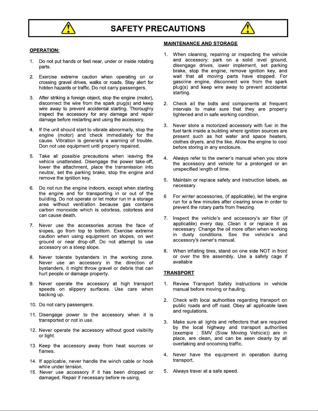
Mahindra BRCXTV44 User manual

1
READ&FOLLOWALLSAFETYRULES&INSTRUCTIONSBEFORE
OPERATINGYOUREQUIPMENT
108562_EN R
-
02162017
*ASSEMBLY *REPAIRPARTS
*OPERATION *MAINTENANCE
*108562*

2
LIMITED WARRANTY
Conditions and Products Covered:
BERCOMAC guarantees any part of the product or accessory
manufactured by BERCOMAC and found in the reasonable
judgment of BERCOMAC to be defective in material and or
workmanship will be repaired or replaced by an authorized
dealer without charge up to our maximum labor rates and pre-
established times. For replacement parts only standard ground
freight services are covered. This warranty applies to the
products bought and used in North America.
Warranty Period
(from date of the original retail purchase)
Residential, light commercial or regular commercial
(agricultural) use: 1 year
Commercial intense, industrial or rental use: 90 days
Exceptions Noted Below; the following items have a different
coverage conditions and limited time:
Tire Chains:
o90 days residential or light commercial use
oNo warranty on other application
Engines: Will vary as per the manufacturer
Please refer to the engine manufacturer’s warranty
statement included with the unit. BERCOMAC is not
authorized to handle warranty adjustments on engines.
Items and Conditions NOT Covered:
This warranty does not cover the following:
Pick-up or delivery charges or in-home services fees.
Any damage or deterioration of the unit, parts and or finish
of these due to normal use, wear and tear, or exposure.
Cost of regular use or maintenance service or parts, such as
gas, oil, lubricants, tune-up parts, and adjustments.
Any part or accessory which has been altered, modified,
misused, neglected, accidentally damaged or not properly
installed, maintained, stored or repaired not in accordance
withtheinstructionsintheowner’smanual.
Repair due to normal wear and or any wear items such as
shear pins, bolts, belts, winch cable, cutting edge, skid
shoes, etc.
Expedited freight fee services for replacement parts.
Shear bolts and shear pins are to be considered as a
preventive measure not as an assured protection, any
damages resulting from the lack of shear bolts breakage are
not covered.
NOTE: All warranty work must be performed by an authorized
dealer using original (manufacturer) replacement parts.
Owner’sResponsibilities:
BERCOMAC’s defective equipment or part must be returned
to an authorized dealer within the warranty period for repairs.
In the event that defective merchandise must be returned to
manufacturer for repairs, freight fees are prepaid and a written
authorization from BERCOMAC must be obtained by dealer
prior to the shipment. This warranty extends only to
equipment operated under normal conditions. To validate a
warranty claim, it is the user’s responsibility to maintain and
servicetheunitasspecifiedintheowner’smanualortohave
the unit serviced at their dealer at their expense.
General Conditions:
The sole liability of BERCOMAC with respect to this warranty
shall be strictly and exclusively repair and replacement as
mentioned herein. BERCOMAC shall not have any liability for
any other costs, loss or damage, including but not limited to,
any incidental or consequential loss or damage.
Taking advantage of the warranty does not in any way extend
the length or renewal of the warranty.
In particular, without being limited to, BERCOMAC shall have
no liability or responsibility for:
Travel time, overtime, after hours time or other
extraordinary repair charges or relating to repairs and or
replacements outside of normal business hours.
Rental of like or similar replacement equipment during the
period of any, repair or replacement work.
Any communicating or travel charges.
Loss or damage to person or property other than that
covered by the terms of this warranty.
Any claims for lost revenue, lost profit or any similar costs
as a result of damage or repair.
Attorney’s fees.
BERCOMAC’s responsibility in respect to claims is limited to
making the required repairs or replacement without charge up
to our maximum labor rates and pre-established times and no
claim of breach of warranty shall be cause for cancellation or
rescission of the contract of sale of any product or accessory.
In no event shall recovery of any kind be greater than the
amount of the purchase price of the product sold.
This warranty gives you specific legal rights. You may also
have other rights, which vary from state to state
.
NOTE: Bercomac reserves the right to change or improve the design of any part or accessory without assuming any obligation to modify
any product previously manufactured.
Instructions for Obtaining Warranty Services: Contact the Mahindra dealer where equipment was purchased or any other Mahindra
service dealer to arrange service at their dealership. To locate a dealer convenient to you, access our website at
www.mahindrausa.com.
Don't forget to bring your proof of purchase (sales receipt) to the Mahindra dealer.
Revised 11-23-2012

TABLEOFCONTENTS
INTRODUCTION
......................................................................................................................................................
1
SAFETYPRECAUTIONS
........................................................................................................................................
2
SAFETYDECALS
....................................................................................................................................................
4
ASSEMBLY
Assemblyinstructions
................................................................................................................................
6
Step1 Engineandbatterypreparation
....................................................................................................
7
Step2 RoughCutterassembly
...............................................................................................................
7
Step3 Installationonthevehicle
............................................................................................................
10
Step4 Controlboxinstallation
.................................................................................................................
11
OPERATION
.........................................................................................................................................................
13
ADJUSTMENTS
.......................................................................................................................................................
18
MAINTENANCE
.......................................................................................................................................................
19
TRANSPORT
.........................................................................................................................................................
22
DISMOUNTINGANDSTORAGE
............................................................................................................................
22
TROUBLESHOOTING
.............................................................................................................................................
23
PARTSBREAKDOWNANDPARTSLIST
44’’RoughCutterBRCXTV44
....................................................................................................................
27
TORQUESPECIFICATIONTABLE
.......................................................................................................................
44
PAGE

INTRODUCTION
TO THE PURCHASER
This new accessory was carefully designed to give years of dependable service. This manual has been provided to
assist in the safe operation and servicing of your attachment.
NOTE: All photographs and illustrations in the manual may not necessarily depict the actual models or attachment, but
are intended for reference only and are based on the latest product information available at the time of publication.
Familiarize yourself fully with the safety recommendations and operating procedures before putting the machine to
use. Carefully read, understand and follow these recommendations and insist that they be followed by those who will
use this attachment.
THIS SAFETY ALERT SYMBOL IDENTIFIES AN IMPORTANT SAFETY MESSAGE IN THIS
MANUAL THAT HELPS YOU AND OTHERS AVOID PERSONAL INJURY OR EVEN DEATH.
DANGER, WARNING, AND CAUTION ARE SIGNAL WORDS USED TO IDENTIFY THE LEVEL OF
HAZARD. HOWEVER, REGARDLESS OF THE HAZARD, BE EXTREMELY CAREFUL.
DANGER: Signals an extreme hazard that will cause serious injury or death if recommended precautions
are not followed.
WARNING:
Signals a hazard that may cause serious injury or death if the recommended precautions are
not followed.
CAUTION: Signals a hazard that may cause minor or moderate injury if the recommended precautions are
not followed.
Record your attachment serial number and purchase date in the section reserved below (there is no serial number on
the subframe). Your dealer requires this information to give you prompt, efficient service when ordering replacement
parts. Use only genuine parts when replacements are required.
If warranty repairs are required please present this registration booklet and original sales invoice to your selling dealer
for warranty service.
This manual should be kept for future reference.
Please check if you have received all the parts for your kit with the list of the
bag and the list of the box.
SERIAL NUMBER : ___________________________
(IF APPLICABLE)
MODEL NUMBER: ___________________________
PURCHASE DATE : ___________________________

2
SAFETY PRECAUTIONS
Careful operation is your best insurance against an accident. Read this section carefully before operating the vehicle
and accessory. This accessory is capable of amputating hands and feet and throwing objects. Failure to observe the
following safety instructions could result in serious injury. All operators, no matter how experienced they may be,
should read this and other manuals related to the vehicle and accessory before operating. It is the owner's legal
obligation to instruct all operators in safe operation of the accessory to prevent accidents or injuries.
These are common practices that may or may not be applicable to the product described in this manual.
GLOSSARY:
In this manual, right and left sides are determined by
sitting on the seat of the vehicle facing forward.
In this manual, "accessories" means attachments
(snowblower, rotary broom, blade, etc.) that you install
on the vehicle (lawn tractors, A.T.V. s etc).
TRAINING:
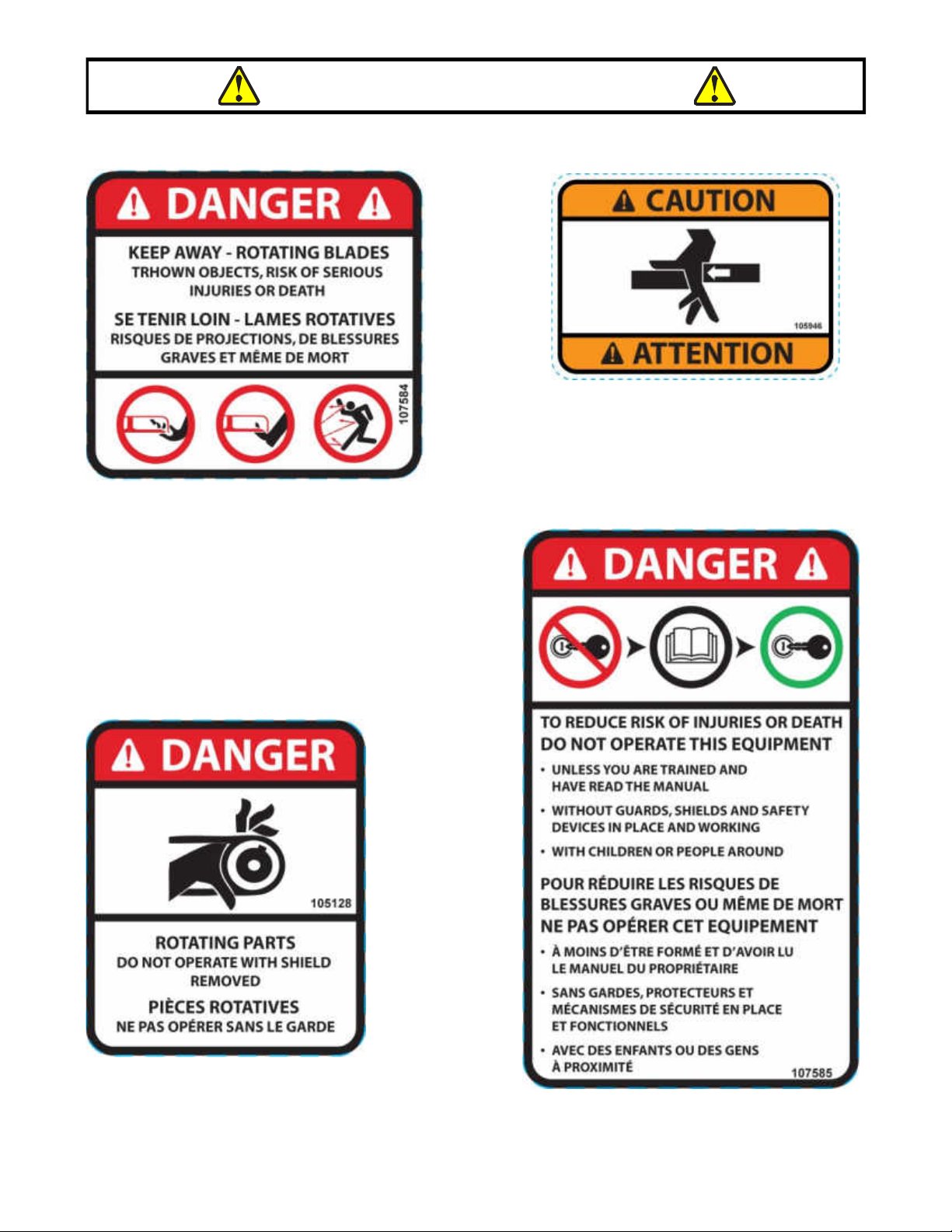
This symbol, "Safety Alert Symbol", is used
throughout this manual and on the
accessory’s safety labels to warn of the
possibility of serious injury. Please take
special care in reading and understanding
the safety precautions before operating the
vehicle and accessory.
1. Read this owner's manual carefully. Be thoroughly
familiar with the controls and proper use of the
vehicle and accessory. Know how to stop the unit
and disengage the controls quickly.
2. Never allow children to operate the vehicle nor the
accessory. Never allow adults to operate the vehicle
nor the accessory without proper instructions. Local
regulations restrict the age of the operator. Children
are often attracted to accessories. Never assume
children will stay in place where you have last seen
them. Keep children under surveillance of a
responsible adult at all times.
3. No one should operate the vehicle nor the
accessory while intoxicated or while taking
medication that impairs the senses or reactions. The
operator should, if taking over the counter drugs,
seek medical advice on whether he/she can safely
operate the equipment.
4. Keep the area of operation clear of all people,
particularly small children and pets.
5. Never start or operate the accessories except from
the operator’s station on the power unit except if
this is impossible.
PREPARATION:
1. Thoroughly inspect the area where the accessory
is to be used and remove door mats, all foreign
objects and the like which could be picked up and
projected by accessory.
2. For motorized accessories, disengage all clutches
and shift into neutral before starting engine.
3. Prepare for emergencies. Be prepared if a fire
starts. Keep first aid kit and fire extinguisher
handy. Keep emergency phone numbers (doctor,
ambulance, ect) near a phone
4. Do not operate the accessory without wearing
adequate clothing and safety equipment. Long hair,
loose clothing or jewelry can get caught in moving
parts. Wear footwear that will improve footing on
slippery surfaces.
5. Handle fuel with care, it is highly flammable and
vapors are explosive.
a) Extinguish all cigarettes, cigars, pipes and other
sources of ignition.
b) Use approved fuel container.
c) Never add fuel to a running engine or hot engine.
d) Fill fuel tank outdoors with extreme care. Never fill
fuel tank indoors.
e) Never fill containers inside a vehicle, or on a
truck or a trailer bed with a plastic liner. Always
place containers on the ground, away from your
vehicle, before filling.
f) When practical, remove gas-powered
equipment from the truck or trailer and refuel it
on the ground. If this is not possible, then refuel
such equipment on a trailer with a portable
container, rather than directly from a gasoline
dispenser nozzle.
g) Keep the nozzle in contact with the rim of the
fuel tank or container opening at all times, until
refueling is complete. Do not use a nozzle lock-
open device.
h) Never overfill fuel tank. Replace fuel cap
securely and wipe up spilled fuel.
i) If fuel is spilled on clothing, change clothing
immediately.
6. Never attempt to make any adjustments while the
engine (motor) is running (except when specifically
recommended by manufacturer).
7. Let the vehicle and accessory adjust to outdoor
temperatures before using.
8. Never use an accessory without proper guards,
plates, or other safety protective devices in place
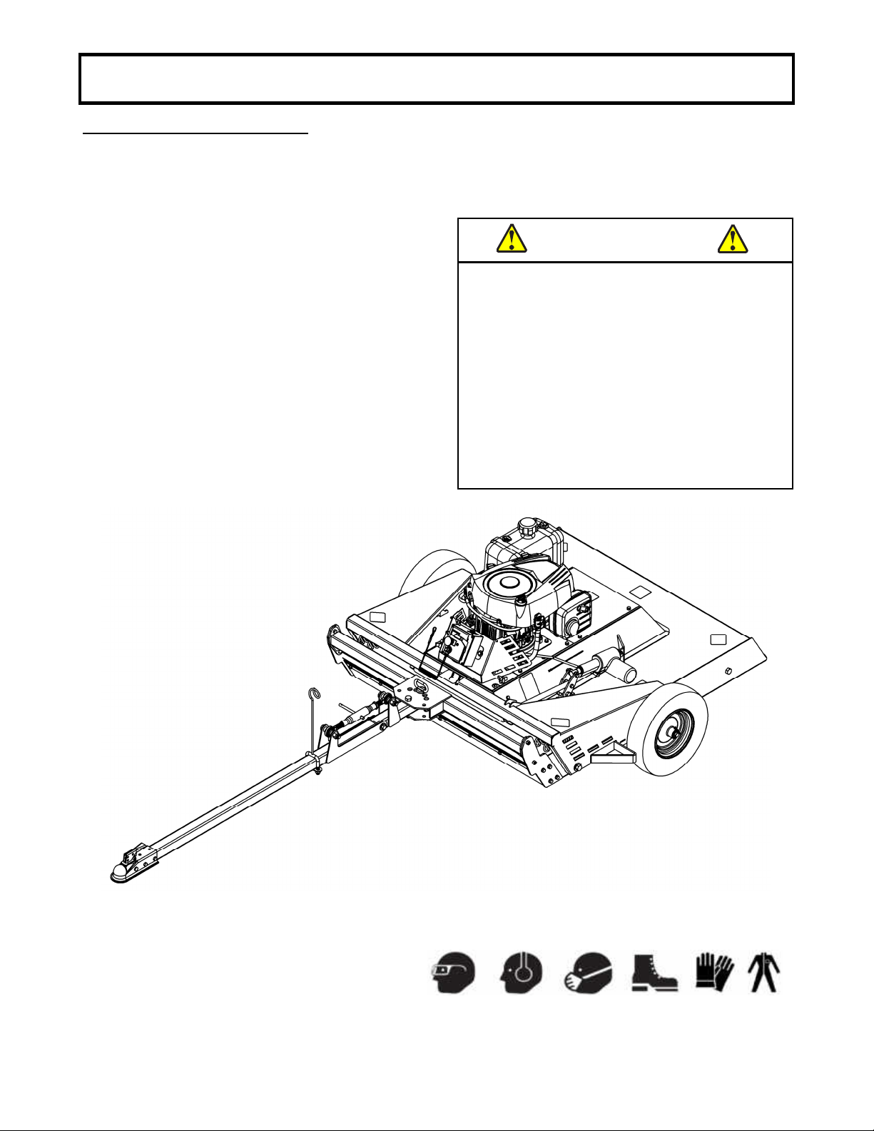
9. Always make sure to wear the appropriate safety
equipment required (glasses, muffs, mask…) for
each type of product. See operation section.
10. Always make sure of having safe traction on the
vehicle by using the recommended accessories
(chains, A.T.V. tracks, coun
terweights…). See
operation section.
11. Always make sure all components are correctly
installed. (driveline securely attached and locked at
bothends,beltsproperlyinstalled…)
12. If applicable, always handle the winch cable with
thick leather gloves.
13. Never modify the accessory or any part without
the written consent from the manufacturer.

3

4
REPLACEIFDECALSAREDAMAGED
SEEPARTSBREAKDOWNFORDECALLOCATION
Decal#107584
Decal#105128
Decal#107585
Toavoidseriousinjury:
Keepallpartsofthebodyawayfrom
movingcomponents.
Decal#105946
SAFETYLABELS

5
REPLACEIFDECALSAREDAMAGED
SEEPARTSBREAKDOWNFORDECALLOCATION
SAFETYLABELS
Decal#108301
Donotstep.
Decal#108261

6
ASSEMBLY
ASSEMBLYINSTRUCTIONS
IMPORTANT:UNLESSOTHERWISESPECIFIEDTORQUEALLBOLTSACCORDINGTOTORQUESPECI-
FICATIONTABLE(SEETABLEOFCONTENTS).REFERTOPARTSBREAKDOWNSECTIONFORPART
IDENTIFICATION.
Overallview
NOTE:Inthismanual,therightandleftsideisdeterminedbeingseatedonthedriver’sseat.
Removeallthecomponentsfromtheshippingcrate
excepttheassembledroughcutterinordertohelp
withtheassembly.
INTENDEDUSE
The 44” Rough Cutter is designed to clear dense
areasofgrassandcutsaplingsinmeadowsandon
smallestates.Itisnotintendedtocreateafinishcut
on lawns. Your Rough Cutter should be towed
behind an ATV, golf cart, lawn tractor or other
approvedvehiclewiththehelpofa2’’(50mm)reach
ball hitch. It is not recommended for speeds
exceeding5mph(8km/h).
Toolsneeded:
Ratchet
Wrench :7/16”,1/2”,9/16”,3/4”,15/16”
Socket:7/16”,1/2”,9/16”,3/4”,15/16”,3/8”
Pliers
WARNING
THISACCESSORYISHEAVY!
To avoid risk of strain injury, NEVER lift the
accessory by hand alone when handling the
components or assembly. Use proper lifting
deviceandseekassistance.
When accessory is off the ground, NEVER be
underneath the accessory. Serious injury
including possibility of death could occur if
accessoryweretodropsuddenly.
Alwayswearprotectiveshoesandappropriate
gloveswhenmanipulatingorusingthis
equipment.
Always make sure to wear the appropriate safety
equipmentrequired(glasses,muffs,mask…).

7
ASSEMBLY
STEP1
ENGINEANDBATTERYPREPARATION
Disengage spark plug wire(s) and place it where it
cannotmakeaconnection.
Add oil in the engine. Verify oil level and add if
necessary before starting engine. (See engine
owner’smanual).
U1batterymustbepurchasedlocally:
Check the battery. If the battery is put into service
afterthe“monthand year”ofthedateonthebattery,
it may need to be charged with a 12 volt battery
charger.Followthemanufacturer'sinstructionsforthe
batteryorforthebatterycharger.
Remove knobs (item 1) and the guard assembly
(item2).
Putthebattery(item3)inplace.
Attach battery cables to the battery, making sure to
attach the red wire to the positive terminal (item 4)
firstandtheblackwireto thenegativeterminal(item
5)second.
STEP2
ROUGHCUTTERASSEMBLY
A)PRE
-
INSTALLATIONOFSPRINGS
Install the hex nut 3/8” n.c. (item 1) onto the 4 eye
boltscompletelytotheendofthethreads.
Install the eye bolts in the holes indicated on the
roughcutterassembly(item3).
Insert the flat washer 7/16” hole (item 4) and tighten
looselyinplacewith4hexnut3/8”n.c.(itme5).
Positionthesprings(item6)withtheendwhichisnot
inserted. In the eyebolts points upwards to facilitate
installationtotheequipment.
Insertthesprings(item6)intheeyebolts(item2).
Donottighteneyebolts(item2)yet.
B)AXLESUPPORTINSTALLATION
Remove the assembled rough cutter from the
shipping crate so that you have access to hole ‘’A’’
over the rough cutter. If necessary, lift the rough
cutterwithajackandsecurewithaxlestands.Make
suretheroughcutterisstableandsecureatalltimes
topreventinjuries.
Insertthebushing(item1)inthehole(itemA)on
eachside.
Insertthesleeve(item2)intheaxlessupport(item
3).
Installtheaxlessupport(item3)withtwohex.bolts
5/8"n.c.x4"(item4),fourflatwashers7/16"hole
(item5)andtwonylonInsertlocknuts5/8"n.c.(item
6)asshown.
CAUTION
PINCHPOINT
TOPREVENTINJURIES:
Manipulatewithcaution.
WARNING
TOPR EVENT INJURY ORD AM AGE:
Itisveryimportanttoplacetheprotectivecover
ontothebattery’sredterminalpost.

8
ASSEMBLY
E)WHEELINSTALLATION
NOTE:Activatetheroughcutterliftsystemtohavea
betteraccesswiththeaxlessupport(item2)and
easethewheelinstallation.
Installthewheelsassembly(item1)ontheaxles
support(item2)andsecurewiththecotterpin3/16"
x1
-
1/2"(item3) .
TIP:Oncethewheelsareinstalled,activatethelift
systemwillhelptoremovetheshippingcratefrom
undertheroughcutter.
D)INSTALLATIONOFTHESPRINGS
TIP:Useacable,hookornylontiewraptoextend
thespings.
Extendthesprings(items1)oneatatimetoinstall
themintotheslotsontheaxlessupport(item2).
Tightenhex.nut3/8"n.c.(item3)oneyebolts(item
4)usingthespecialsocket9/16"(item5).
NOTE:Activatetheliftmechanismofthecutterto
betterpositiontheaxlessupport.
Forinstructionsseesection« OPERATION »
« FAMILIARIZATIONWITHTHECONTRÔLBOX ».
NOTE:Whenthecutterisnotrestingontheground
onitswheels,theactuator’srodmayberetractedby
thespringload.Thismayhappenwithanunope-
ratedactuator.
Ifthishappens,theaxlessupportwillnotbeinthe
bestpositiontotightenthenuts(item3).Thesolution
willthenbetotightentheseoncethecutterinresting
onthegroundonitswheels.
CAUTION
PINCHPOINT
TOPREVENTINJURIES:
Manipulatewithcaution.
C)LIFTLINKINSTALLATION
.
Installoneendoftheliftlink(item1)ontheliftlever
(item2)oftheroughcutterusingthehex.bolt3/8"
n.c.x21/4"(item3),thewashers(item4)andone
nyloninsertlocknut3/8"n.c.(item5).Installthetwo
spacers(item4)asshowntocentertheliftlink(item
1)betweenthetwoliftlevers.
Slightlytightenthenut.
Installtheotherendoftheliftlink(item1)onthe
axlessupport(item6)byinsertingthepin(item7)into
theholeandsecurewithhairpin2.5mm(item8).
4

9
ASSEMBLY
F)REARHITCHASSEMBLY
1) Install the hitch (item 1) to the intermediate hitch
bar(item2)usingtwohex.bolts3/8"n.c.x3"(item3)
andtwonyloninsertlocknuts3/8"n.c.(item4).
2) Install the rear hitch bar (item 1) on the
intermediatehitchbar(item2)withonehex.bolt1/2"
n.c.x3 1/2" (item3)twoflatwashers1/2"hole(item
4),thesleeve (item 5)andonenyloninsertlocknut
1/2"n.c.(item6).
Donottightenfirmlyastoletthehitchprivot.
CAUTION
PINCHPOINT
TOPREVENTINJURIES:
Manipulatewithcaution.
3) Installthetoplink(item1)tothehitchbars(item
A)usingtwohex.bolts5/8"n.c.x31/2"(item2),four
sleeves (item 3) nylon insert lock nut 5/8" n.c. (item
4).
4) Adjustthetoplink(item1)to131/2 inchescenter
tocenter.
5)Installthecableholder(item1)ontheintermediate
hitch bar (item A) with the U
-
bolt and plate (item 2)
andtwonyloninsertlocknuts1/2"n.c.(item3).
NOTE:Positionthecableholdernearthetoplink.
You may re
-
adjust this location to avoid any
interference with the control cables while towing
vehicleisinmotion.

10
ASSEMBLY
STEP3
INSTALLATIONONTHEVEHICLE
A2’’(50mm)BALLHITCHISREQUIREDONTHE
TOWINGVEHICLE.
Backthevehicleuptodesiredtowingposition.
Placethehitch(item1)onthetowhitchballand
secureinplacewithapin(item2)andahairpin
(item3).
NOTE:Correctadjustmentwillallowthehandletobe
releasedwithmoderatepressureappliedtothe
handle.
Toopen,pulluponhitchcouplerhandleandrotate
forward.
Placehitchcoupleronball.
Whenballiscompletelynestedinsocket,rotatehitch
couplerhandlebackwarduntilhandleisinlocked
position.
Alwayschecktightnessbeforeusingthetowhitch.
Lockthehandle(item1)intopositionovertheballin
thehitchcoupler.Tightenthelocknut(item2)against
thespringsothatthehitchcouplerisnotlooseonthe
ball.
Besurehitchcouplerhandleisinlockedposition.
WARNING
TOPREVENTINJURIES:
Alwayscheckthatballiscompletelyinsertedinto
hitchcouplersocketandthatunderjawissecurely
closedaroundthebottomofball.
Alwayscheckthathitchcouplerhandleisproperly
lockedbeforeitsuse.
Always examine hitch coupler and ball for damage
beforeusing,replaceifdamaged.
Adjustingthehitchcoupler
G)TOWBARINSTALLATION
Insertthesleeve(item1)intothecorrespondinghitch
barhole(item2).
Alignholesandinstall,asshown,thehitchbar
assembly(item2)withthesleeveontheroughcutter
assembly(item3)usingahex.bolt5/8"n.c.x3
1/2"(item4)andanyloninsertlocknut5/8"n.c.(item
5).
Finally,securethepositionofthehitchbarwiththe
pinwithhairpin4mm(item6).
See“ADJUSTMENT”sectiontoselecttheproper
hitchbarorientationfortheapplication.
Reconnectthesparkplugcable(s).

11
STEP4
CONTROLBOXINSTALLATION
1) Removecontrolbox(item1)fromguard(item2)
bylooseningtheknob(item3).
TIP:Replacetheknobonguardandtightensecurely
toavoidlossofknobduetovibrationwhileinuse.
2)Installtheo
-
ring(item1)ontheboxsupport(item
2)usinghex.bolt5/16"n.c.x3/4"(item3),flat
washer3/8"hole(item4)andnyloninsertlocknut
5/16"n.c.(item5).
Donotovertighteno
-
ring.
Usetheslot(itemA)onthecontrolboxtoavoidover
tighteningandtomakesureitiswellinserted.
3)Choosebetweenthetwowaysofinstallingthe
controlboxsupport(item1).
NOTE:Inordertopreventdamageduetowater
accumulation,makesuretoplacethecontrolbox
horizontally.
OptionA
Usetwohexbolts1/4"x11/2"(item2),twospacers
(item3)andtwoflangenuts1/4"(item4)toattachthe
controlboxsupporttothesupportbrackets(item5).
NOTE:Choosetherightholecombinationonthe
controlboxsupportinordertoorientthefrontofthe
controlboxtowardsthedrivingcontrolsofthevehicle.
(seeoperationsectiontoseehowcontrolboxis
oriented),Furthermore,makesuretohavefree
accessatalltimestotheequipment'scontrolsin
ordertosafelycontroltheequipment.
OptionB
Drilltwoholesof19/16’’apartonthevehicle.Secure
thecontrolboxsupportwithtwobolts1/4"x1/2"(item
6)andtwoflangenuts1/4".
Insertthecontrolboxinthecontrolboxsupport.
ASSEMBLY

12
INSTALLTHECONTROLBOXINITSSUPPORT
Putthecontrolbox(item1)initssupport(item2).
Secureonplacewiththeknob(item3).
SECURECABLES.
Insertthecables(item1)throughtheopeningofthe
cableholder(item2).
IMPORTANT:Becarefultosecurethecablesto
avoidanydamagecausedbyacontactwiththe
vehicle,equipmentitself(especiallyengineexhaust)
oranyotherobjectthatcanbefoundintheareaof
thesecables.
Attachtheelectricalcableandtheenginecontrol
cabletotheequipmentandtothevehicle,if
necessaryusecableties.
Donotforget:thecontrolboxmustbeeasily
removablefromvehicle.
Ifneeded,re
-
adjustthepositionofthecablesupport
(item 2) to avoid any interference with the control
cableswhiletowingvehicleisinmotion.
IMPORTANT:Beforeoperatingthisequipment
proceedwithalltheadjustmentsrequiredinsection
« Adjustments ».
ASSEMBLY

13
DANGER
Tragicaccidentscanoccuriftheoperatorisnotalert
tothepresenceofchildren.
Childrenareoftenattractedtotheequipmentandthe
mowing activity. Never assume that children will
remainwhereyoulastsawthem.
DANGER
ALWAYS OPERATE FROM THE DRIVER’S SEAT
AND ALWAYS INSTALL ON YOURSELF THE
EMERGENCYSWITCHLANYARDTHATISLINKED
TOTHECONTROLBOX.
NEVEROPERATEWITHOUTTHISLANYARD.
OPERATION
OPERATOR’SRESPONSIBILITY
Hazard control and accident prevention are dependent upon the awareness, concern, prudence and proper
training involved in the operation, transport, storage and maintenance of the Rotary Cutter. Therefore, it is
absolutely essential that no one operates the Rotary Cutter without first having read, fully understood and
becometotallyfamiliarwiththeoperator'sManual.MakesuretheoperatorhascompletedtheoperatingCheck
listbelow.
SAFETYINFORMATION
DANGER
TOPREVENTINJURIES:
Allguardsandshieldsmustbeinstalledandingood
workingconditionatalltimesduringcutteroperation.
DANGER
TOPREVENTINJURIES:
Keep others away while cutter isoperating. It can
discharge objects at high speeds. Therefor, the
use of front and rear safety guards is strongly
recommended when cutting along highways and in
areas where people may be present. Stop blade
rotationifabystanderiswithinatleast300feet.
DANGER
TOPREVENTINJURIES:
Never place handsorfeetunderthedeckorattempt
to make adjustments to the cutter with ELECTRIC
CLUTCH engaged. Cutter blades rotating at high
speedscannotbeseenandarelocatedclosetothe
deck housing. Body extremities can be cut off
instantly.
DANGER
TOPREVENTINJURIES:
Do not operate and/or travel across steep inclines
whereavehiclecanrolloverresultinginseriousinjury
ordeath.
Consultyourvehicle’smanualforacceptableinclines
the vehicle is capable of traveling across. Never
operateonslopesofmorethan15degrees.
DANGER
TOPREVENTINJURIES:
Do not use cutter as a fan. Cutting blades are not
properly designed or guarded for this use. Using
cutterasafancanresultininjuryordeath.
Always make sure to wear the appropriate safety
equipmentrequired(glasses,muffs,mask…).
WARNING
TOPREVENTINJURIES:
Never allow riders includingchildrenonthevehicle
orcutter.
Theycanfalland be ran overcausingserious injury
ordeath.
The operation of any mower can produce foreign objects to be thrown into the eyes, resulting in severe eye
damage.
Always wear certified safety glasses or wide
-
vision safety goggles over spectacles before starting any cutting
machineandwhileoperatingsuchamachine.
The operation of any mower produces sound waves that are damaging to the human ear. Ear protection is
recommended.
WEARYOURSAFETYGLASSESFORESIGHTISBETTERTHANNOSIGHT

14
OPERATION
Item1:Ignitionswitch.
Usingthekey:Allowstostarttheengineor youmay
turn the key to the accessory setting to activate the
controlswithoutstartingtheengine.Thelight(item7)
isonwhenthekeyisturnedtotheaccessoryorstart
setting.
Always remove the key when the equipment is left
withoutsurveillance.
Item2:Throttlelever
Push towards the front to increase engine speed,
pushcompletelytotheendto‘’start’’
Item3:Emergencyswitch
Pushtostopequipmentquickly.
Item4:Safetylanyard:
Links the operator to the control box. If the operator
leaves the driver’s seat without stopping the
equipment, the equipment will stop (the cable will
disconnectitselffromthecontrolbox).
7
3
5
8
4
2
1
6
front
back
1
Stop
Accessory
Enginestart
Enginerunning
WARNING
TOPREVENTINJURIES:
Always disengage electric clutch, engage parking
brake,shutoffvehicle,removeignitionkey,andwait
for all moving parts to come to a complete stop
beforedismountingfromvehicle.
WARNING
Itisapossibilitythatincertaincases,thesafety
lanyard may be too long and will not function
properly due to where the control box is
installedonthevehicleandwherethelanyardis
attachedtotheoperator.
ITISTHEOPERATOR’SRESPONSIBILITY
Tomakesurethatthelanyardiswellinstalledsothe
equipmentstopswhentheoperatorleavestheseat.
IFREQUIRED:
Shorten the lanyard making sure it retains its
originalandadequateresistance.
FAMILIARIZATIONWITHTHECONTROLBOX
Item5:Engagementswitch
Pulltoengage,pushtodisengagetheelectricclutch.
Thelight(item8)isonwhenequipmentisengaged.
Item6:Heightadjustmentswitch.
Allowstoadjustthecuttingheight.
WARNING
Readthevehicle'sowner’smanualcarefully.Be
thoroughly familiar with the controls & proper
use of the attachment. Know how to stop the
unit&disengagethecontrolsquickly
.

15
OPERATION
WARNING
TOPREVENTINJURIES:
Do not operate cutter with loose hardware. Loose
hardwarecan resultinabreakdowncausingserious
injuryordeath.
WARNING
TOPREVENTINJURIES:
Donotusecuttertoliftorcarryobjects;topullfence
posts, stumps or other objects; or to tow other
equipment. Doing so can damage the cutter, cause
seriousinjuryordeath.
CAUTION
TOPREVENTINJURIES:
Do not exceed rated cutting capacity of your cutter
(see«
INTENDEDUSE »
section).
WARNING
TOPREVENTINJURIES:
Clear area to be cut of debris and other unforeseen
removableobjectsbeforecutting.Markanypotential
hazards that cannot be removed such as tree
stumps, post, rocks, holes, and drop
-
offs with a
visibleflag.
WARNING
Loosebladescaneasilypiercea¼”steelplate.
Loosebladescanalsobethrownupto300feet.
TOPREVENTSERIOUSINJURIES,DEATHAND
MATERIALDAMAGE:
Periodically (and after a full day) disengage
ELECTRIC CLUTCH, shut down engine, remove
key,and:
Checkforforeignobjectswrappedaroundtherotor
shaft.
Blockcutterdeckupbeforeremovingobjects.
Frequently inspect cutter for any sign of wear or
loose bolts and nuts (especially the stump jumper
andthebladebolts).
TightenasindicatedintheTorquespecification
table.
Makesureallguardsareinplaceatalltimes.
BEFOREFIELDOPERATION:
INSPECTVEHICLE
Vehicle must respect the maintenance
specificationsaspertheowner’smanual.
Inspect vehicle safety equipment to make sure it is
installedandingoodworkingcondition.
ENGINEPREPARATION
See engine manufacturer’s recommendations for the
typeandamountofoilandfuelused.
Make sure the tow vehicle parking brake is set,
mower is level, and blades are disengaged. Engine
must be level to accurately check and fill oil. Do not
overfill.
Checksparkplugwire(s),oil,andfuel.
Checkallelectricalconnectionsfordebrisbuildup.
Opérerlemoteurselonlesinstructionsdumanueldu
moteur.
ADJUSTCUTTER
Before operating equipment refer to section
« Adjustment »andproceedwithadjustments.
ADJUSTTIREPRESSURE
Verifyandadjusttirepressureasindicateddirectlyon
tireoftheequipment.Pressuremustbeeveninboth
tires.
PRE
-
INSPECTIONOFVEHICLE&CUTTER
Makethefollowinginspectionswithcutterattachedto
a vehicle, ELECTRIC CLUTCH disengaged, and all
movingcomponentscompletelystopped:
Parkvehicleandcutteronalevelsurface.
Inspect cutter safety equipment to make sure it is
installedandingoodworkingcondition.
With cutter resting on solid supports, ELECTRIC
CLUTCH disengaged, and blade rotation completely
stopped:
Makesurethereisnothingunderthecutterthat
shouldnotbethere.
(tools,block,feet,hands,etc.)
Check for and remove foreign objects wrapped
aroundbladespindles.
Check for nicked, bent, broken, and worn cutting
blades.
Replace or sharpen blades as required.
Referto“CutterBladeMaintenance”.
Removesolidsupportsfromunderthedeck.
INSPECTWORKAREA
Makesuretheworkareacorrespondstotheintended
useofthisequipmentandissafetoworkwithin.
Do not cut in wet conditions. Allow wet grass to
dry. Wet grass will clump and collect under the
mowing deck.Wetmaterial will build up onthe deck
underside creating poor discharge and high wear. It
willalsorequireadditionalhorsepower.

16
OPERATION
WARNING
TOPREVENTINJURIES:
Stop ELECTRIC CLUTCH immediately if vibration
continues after a few evolutions during start
-
up and
anytimethereafter.Waitforallmovingpartstocome
to a complete stop before dismounting from vehicle
to check for probable causes. Make necessary
repairsandadjustmentsbeforecontinuing.
WARNING
TOPREVENTINJURIES:
Start the engine, engage and disengage the
electric clutch to be sure it functions normally.
Make sure the emergency switch is working
perfectly.Makesureallthecontrolsareworking
well.
IMPORTANT:
If excessive vibrations continue after 3seconds atfullenginespeed, disengage the blades immediately,
shutdownengine,andremoveswitchkey.
Checkbladesforalock
-
upsituation.Blockcutterdeckupbeforeworkingundertheunit.Unlockblades,
removesupportblocks,andrepeat“BladeEngagement”instructions.
BURNISHINGPROCEDURE
Theburnishingproceduremustbeperformedbeforethefirstutilisationoftheaccessoryandafteraprolonged
periodofinactivity.Burnishingtheengagingsystemwillensureproperperformanceandwillhelpavoid
damages.
1. Makesurethebladesarefreeofanyobstruction.Starttheengine.
2. Engageelectricclutch.
3. Disengageelectricclutchandwaitforallmovingpartstostop.
4. Repeatprocedure(steps2&3)10timeswithin30secondsintervalstoavoidoverheatingtheclutchwhich
mayresultindamage.
STARTINGTHEENGINE
Before starting to work, sit on the driver’s seat and always install on yourself the emergency switch
lanyardthatislinkedtothecontrolbox.
NOTE:Donotattempttostarttheunitwithengagementknobpulledupinthe“ENGAGED”position.
Usingthecontrolbox,followthesesteps:
Setthethrottleeveronthecontrolboxto“START”position.
Turnkeytothe“ACCESSORY”setting,thentothe“START”setting.
SetthrottlelevertominimumRPM.
Allowenginetoidleafewmomentsbeforeengagingtheblades.
BLADEENGAGEMENT&DISENGAGEMENT
Theremaininginspectionsaremadebyengagingthebladestocheckforvibrations.
Cutterbladescanlock
-
upagainsteachotherduringstart
-
upandshut
-
down.
FollowingBladeEngagementandBladeDisengagementinstructionsbelowwillhelpeliminatebladelockup.
BLADES(ELECTRICCLUTCH)ENGAGEMENT
a)Make sure the engine is running at idle or slightly
above.
b)While engine is running at idle, engage the blades
bypullinguptheengagementswitch.
NOTE: Initialstart
-
up vibration is normal and should
stopafterafewrevolutions.
c)Once cutter is running smoothly, slowly increase
enginespeed.
IMPORTANT: Afterrampinguptoenginefullthrottle,
ensure that rough cutter is not vibrating excessively
foratleast3seconds.
BLADES(ELECTRICCLUTCH)DISENGAGEMENT
a)Slowly decrease throttle speed until engine idle
speedisreached.
b)Then, push down the engagement switch to
disengagetheblades.
c)Engagevehicleparkbrake,shutvehicleengineoff,
andremoveswitchkey.Stayonvehicleuntilblades
arecompletelystopped.
STARTINGTHEENGINE,INSPECTIONSANDBURNISHINGTHECLUTCH

17
OPERATION
BREAKINGINYOURCUTTER’sBELT
Set the vehicle parking brake and chock the
wheels.
With the engine running at minimum rpm, slowly
engagetheblades.
In a safe environment, (i.e. no children or pets)
allow blades to rotate and engine to idle for 5
minutes,breakinginthebeltforalongerlife.
Stopcutter.
STOPPINGTHEENGINE
Makesurethetowvehicleparkingbrakeisset.
Disengagecuttingblades.
Reduce engine to idle speed and allow engine to
runmomentarilyforcooling.
Turnthekeytothe’’OFF’’setting.
STARTINGTOCUT
Adjust the cutting height using the height
adjustmentswitchonthecontrolbox.
Doublecheckthatcutteriswellattachedtovehicle.
Always follow the “starting the engine” instructions
on the preceding page, start the rough cutter
engine.
Engagethebladesfollowingtheinstructionsonthe
precedingpages.
Startmowingataslowtravelspeed.
IMPORTANTDURINGFIELDOPERATION
Donotuseequipmentdrivingbackwards.
Your cutter is equipped with free swinging cutting
bladestoreduceshockloadswhenstrikingobstacles.
However, it is best to avoid striking obstacles to
extendcutterandbladelife.
Periodically disengage ELECTRIC CLUTCH, turn
off engine, remove key & check for objects wrapped
aroundbladespindle.Blockdeckupbeforeremoving
objects.
Frequently inspect cutter for loose boltsand nuts.
TightenallloosehardwareasindicatedintheTorque
specificationtable.
STOPPINGTHECUTTINGSESSION
Bringtowvehicletoacompletestop,settheparking
brakeanddisengageblades.
Turnkeyswitchtothe“OFF”setting.
Always remember to remove keys to avoid
accidentalstartorirresponsibleusage.
TRANSPORTINGCUTTER
StopTrailCutter.
PlaceTrailCutterdeckinitshighestposition.
See section « Transportation » to transport
equipmentsecurely.
SUGGESTEDCUTTINGPRACTICES
Maintaincorrectenginespeed.
Loss of engine speedwillallowbladestoswing
backresultinginragged,unevencutting.
Correct engine speed willassurethebestcutting
performanceandmaximummaterialdischarge.
Excessive engine speed will increase the
vibrations and the risk to cause faster damage to
thepowertraincomponents.
Afterthefirst50feetofcutting:
Stoptravelinganddisengagetheelectricclutch.
Checkcutterlevelnessandcuttingheighttomake
certainitisadjustedproperly.
Optimumgroundspeed:
It depends on density of material being cutand
terrain.
The rough cutter should be started with tow
vehicle at low seep and increased only as safe
mowingconditionspermit.Cuttingspeedshould
notexceed5mph(8km/h).
Optimumgroundspeedmayvarybetween2to5
mph (3 to 8km/h) to allow the cutter to make a
smoothcutwithoutluggingtheenginedown.
Cuttingconditionsandthetypesofgrassorbrushwill
vary from place to place. You mayfind when cutting
dense areas that the pressure of the wheel tracks
may cause the grass to be pushed down and not
effectively mowed. If this happens you may want to
mowthe areatwice.Once withthecutterraisedand
thesecondcuttingatthedesiredheight.Thesecond
cuttingshouldbeatarightanglefromthepreviousfor
bestresults.
Reducingthetravelspeedwillhelpcutdensegrowth.
Thisallowsthebladesthetimenecessarytomakeits
initial cut, and regain momentum to continue cutting
anddischargingdebrisproperly.Theenginemaystall
ifyouaremowingtoofast!
Do not attempt to cut areas that the tow vehicle
cannot maneuver through and/or slopes that you do
notfeelcomfortableriding.
BRAKINGYOURCUTTER’SBELT&FIELDOPERATION
Table of contents
Popular Cutter manuals by other brands

Simplex
Simplex CCD0075 instruction manual

Atlas Copco
Atlas Copco DC 200 Safety and operating instructions

flexbar
flexbar ReproCut 16139 Operation manual

SignWarehouse.com
SignWarehouse.com Bobcat BA-60 user manual

Parkside
Parkside PFSM 500 A1 Translation of the original instructions

Jula
Jula 556-004 operating instructions