MAHLE ACX150 User manual

MAHLE ACX150/250
SERVICE MANUAL
RHLE

EN | 1 | ACX150/250 | Contents
© MAHLE
1Contents
1Contents 1
2General instructions 3
2.1General Notes 3
2.2General instructions 3
2.3Manufacturer identification 3
3Safety conditions 3
3.1Personal safety information 3
3.1.1Definitions 3
3.1.2Personal safety
information 4
3.1.3Important information on
service equipment safety 7
3.2Safety devices 7
3.3Environmental precautions 7
4Layout of the manual 8
4.1Use of the manual 8
4.2Symbols 9
4.2.1Safety 9
4.3Glossary 9
4.4Guidelines for the handling of
refrigerant 10
4.4.1Precautions for
refrigerant storage 10
4.4.2Conditions of refrigerant
and system 10
4.4.3Recycling capacity 10
5Installation 11
5.1Equipment installation 11
5.1.1Unpacking ACX150/250
11
5.1.2Refrigerant scale
unlocking 12
5.1.3Positioning and
connection 12
5.1.4Setup 12
6Maintenance 14
6.1Report exporting 14
6.2Internal cylinder fill 14
6.3Self leak test 15
6.4Cylinder pressure check 15
6.5Cylinder refrigerant view 15
6.6Air purge system 16
6.7Air purge 16
6.8Pressure zero 16
6.9Counters 16
6.10E³ PUMP - vacuum pump oil
change 16
6.10.1Oil pump visual check 17
6.11Dryer filter replacement 17
6.12System info 18
6.13System update 18
6.14Maintenance of printer
(optional) 19
6.15Periodic checks 19
7Calibration 20
7.1Service KIT 20
7.2Pressure calibration (service
kit) 20
7.3Gas weight calibration
( service kit) 21
7.4Oil weight calibration (service
kit) 22
8Update 23
8.1Software update 23
8.2New database 23
9Equipment and simulator 24
10Refrigerant fluid circuit 24
10.1Refrigerant fluid circuit 24
10.2Operational cycles 24
10.3Receiving tank 24
10.4Manifold chart 25
10.5Suction unit chart 26
11Non-permanent junction 26
12Electrical connections 27
13Spare parts 27
14Replacement interventions 27
14.1Extraordinary maintenance list
27
14.2Extraordinary maintenance 28
14.2.1Replacement of
component connected to refrigerant
circuit 28
14.2.2Replacement of logic
electronic board with display 28
14.2.3Replacement of
electronic power board 29
15Trouble shooting 30

EN | 2 | ACX150/250 | Contents
© MAHLE
16Diagnostic 30
16.1Failure list 30

EN | 3 | ACX150/250 | General instructions
© MAHLE
2General
instructions
2.1 General Notes
All rights reserved.
This manual may not be reproduced, in
part or entirely, either in printed or digital
form.
It may be printed out solely for use by the
user and operators of the equipment to
which it refers.
MAHLE and resources used for the
drawing up of this manual will not be held
responsible for the incorrect use of the
manual while they guarantee that
information in the manual have been duly
checked.
The product can be subject to changes
and improvements. MAHLE reserves the
right to change without notice the
information contained in the manual.
2.2 General instructions
Pressure equipment undergoes checks
before commissioning and periodical
checks during operation, in compliance
with rules and law provisions in force in
the country where the tool is used.
The operator is responsible for operating
the equipment in conformity with local
legislation.
ACX150 is designed for recovering and
recycling R134a refrigerant fluid from
automotive A/C plant (it is possible to
switch for R1234yf refrigerant by an
authorized Mahle Service Centre).
ACX250 is designed for recovering and
recycling R1234yf refrigerant fluid from
automotive A/C plant.
The equipments are intended to be used
by automotive and similar repair and
service workshops.
This equipment is intended solely for use
by professionally trained operators
familiar with the basics of refrigeration,
refrigeration systems, refrigerants and the
hazards associated with pressurised
equipment. Careful reading of the present
manual by the owners, the users and the
operators is required for a correct and
safe use of the tool. The user shall not be
entitled to open the product since
maintenance operations are reserved to
the authorised service centre.
2.3 Manufacturer
identification
The ACX equipment is manufactured by:
MAHLE Aftermarket GmbH
Service Solutions Europe
Pragstr. 26 - 46, 70376 Stuttgart,
Germany
Phone: +49 711 501-14003
3Safety conditions
3.1 Personal safety
information
3.1.1 Definitions
DANGEROUS AREAS:
Any area within or close to the equipment
implying risk for the safety and health of
exposed persons.
EXPOSED PERSON:
Any person completely or partially
standing in a dangerous area.

EN | 4 | ACX150/250 | Safety conditions
© MAHLE
OPERATOR:
The person/s charged with operating the
machine for its intended purpose.
CLASSIFICATION OF OPERATORS
The operator can be classified according
to two main categories, which, in some
cases, refer to one single person:
The operator charged with the
equipment operation has the
duty to:
oStart up and monitor
the machine's
automatic cycle;
oCarry out simple setting
operations;
oRemove the causes of
equipment stop not
implying breakings of
members but simple
operating anomalies.
Maintenance technician a
technician trained by an
authorised MAHLE centre,
capable of working on the
machine’s mechanical and
electrical components with its
guards open to make
adjustments and to service and
repair it.
USER
Body or person legally responsible for the
equipment.
3.1.2 Personal safety information
The MAHLE ACX150/250 A/C service
station is particularly simple and reliable
due to its adjustments and functions.
When used correctly it presents no
hazard for the operator, provided he
observes the following general safety
instructions and that the service station is
regularly serviced (incorrect
maintenance/use compromise the
equipment's safety).
Before operating the service station for
the first time, read these instructions
carefully. If any part of the instructions is
unclear, contact your reseller or MAHLE.
This service station may be used by only
one equipment operator, familiar with A/C
and refrigeration systems and the hazards
associated with refrigerants and high
pressure equipment.
WORKPLACE: ACX150 can work with
R134a or R1234yf (after gas switch
procedure/transformation by Mahle
Authorized Service Centre). ACX250 can
work with R1234yf.
Refrigerant R1234yf is defined as
flammable refrigerant.
Nonetheless, although refrigerant R134a
is not defined as flammable, mixtures of
air or oxygen with R134a may become
flammable under very particular
conditions.
The equipment must be operated
outdoor or in a well-ventilated location
(at least 1 air change per hour). The
workshop has to be equipped with
ventilation systems able to ensure air
change in every environment area or
carry out periodical ventilation by
opening the areas.
Use the equipment away from heat
sources or hot surfaces. The equipment
must not be used in explosion risk
environments (potentially explosive
atmospheres). Before using it, put the
equipment on a leveled plane and secure
position, blocking it with suitable wheel
stops.

EN | 5 | ACX150/250 | Safety conditions
© MAHLE
Do not expose the tool to direct sunrays,
heat sources, rain and jets of water. Do
not smoke near the equipment and during
operations (keep at a distance of at least
1 m).
The work area must be monitored by the
operator while the equipment is operating.
ATTENTION: R134a and/or R1234yf
refrigerant fumes/gases are heavier than
air and can gather on the floor or inside
cavities/holes and cause choke by
reducing the oxygen available for
breathing.
At high temperatures, the refrigerant
breaks down releasing toxic and
aggressive substances, harmful for the
operator and the environment.) Avoid
inhaling the system coolants and oils.
Exposure can irritate eyes and the
respiratory tract.
ELECTRICAL CONNECTION: Connect
the power cord solely to a mains supply
which conforms to the ratings on the
machine's nameplate (mounted on its
side). Make sure the mains socket is
grounded.
Maximum impedance allowed in the point
of connection to the mains shall comply
with standard EN 61000-3-11. Starting
currents can cause short voltage drops,
which may affect other equipments under
unfavourable conditions. If impedance in
the point of connection to the mains is
not compliant, this may lead to
interference so please consult the
electrical power network operator before
connecting the equipment.
Never use the service station with a
defective power cord or a different one
from that supplied with the machine. If
damaged, immediately have it replaced
with an original spare part or equivalent
by a MAHLE centre. Before opening the
service station, extract completely the
supply cable from the plug, or you can
get an electric shock.
Do not tamper with or bypass the safety
equipment and settings.
Do not leave the machine powered up
when not in use; shut off the power
supply before leaving the equipment
unused for a long time. Do not forget that
the tool (pressure tool) must always be
protected.
REFRIGERANTS AND LUBRICANTS -
PERSONAL SAFETY EQUIPMENT AND
PRECAUTIONS: The refrigerants and the
pressure cylinders have to be handled
with care, otherwise there will be possible
health risks.
The operator must wear safety glasses,
gloves and protective clothing suitable to
the work. Contact with the refrigerant can
cause blindness (eyes) and other physical
damages (freezing) to the operator. Avoid
contact with the skin; the refrigerant's low
boiling point (approx. –26 °C for R134a
and approx. -30 °C for R1234yf) can
cause freezing burns.
Further information about safety can be
obtained from the safety sheets of
lubricant and refrigerant producers.
Do not inhale refrigerant or oil vapor.
Keep away from the vent valves and
ventilation coupling, especially when non-
condensable gas is being vented.
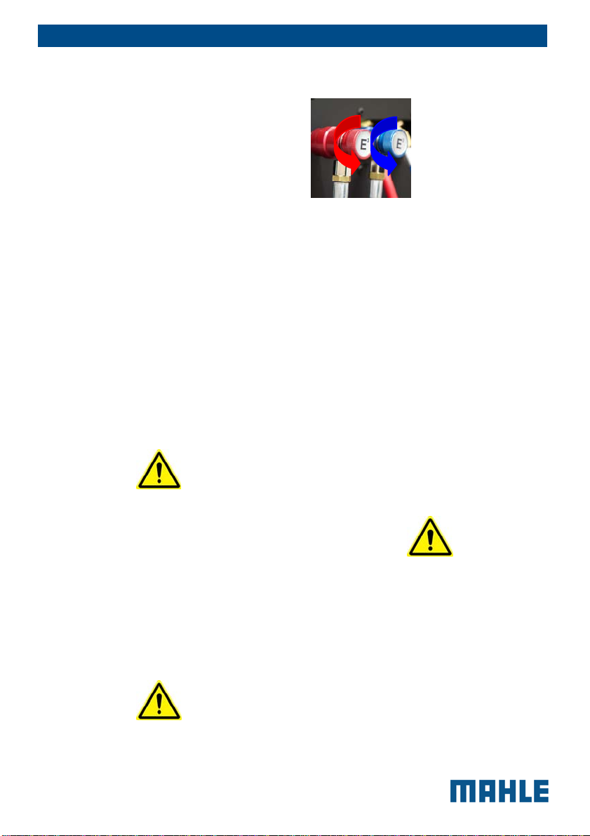
Never direct the quick couplings (taps)
towards your face or other persons or
animals.

EN | 6 | ACX150/250 | Safety conditions
© MAHLE
OTHER PROHIBITIONS AND USE
LIMITATIONS: Only use pure R134a or
R1234yf refrigerants, refrain from using
on vehicles containing other types of
refrigerants or mixtures of the two
refrigerants or other refrigerants.
Mixture with other types of refrigerant
produces serious damage to the
conditioning and cooling systems. Mixed
refrigerants have to be disposed of
according to the current regulations.
Never use ACX equipment with systems
containing compressed air; mixtures of
R134a or R1234yf with air or oxygen may
be potentially flammable.
Do not modify calibration of safety
devices. Do not remove seals of safety
valves and of control systems. Do not use
external tanks or other storage containers
that are not type-approved or without
safety valves.
Make sure the equipment's aeration and
ventilation ports are not obstructed or
covered while the equipment is operating.
HOSE CONNECTIONS: Hoses may
contain pressurized refrigerant. Before
changing the service couplers, check the
respective pressures in the hoses
(pressure gauge). Before connection to a
car A/C system, to an external
tank/cylinder, check that the quick
couplers are closed (unscrewed HP and
LP valves). Scrupulously follow the
instructions on the equipment's display.
QUICK COUPLERS
CLOSING/OPENING:
MAINTENANCE/GENERAL CLEANING:
The equipment has to be serviced at the
intervals indicated by the equipment itself.
The service station maintenance has to
be performed according to the
procedures described in this manual and
to the current safety regulations.
Use only MAHLE original parts.
When the equipment requires the drier
filter and the vacuum pump oil to be
changed, you have to be careful in the
replacement.
A/C service station maintenance can be
carried out exclusively by a trained
operator or by a service man of a MAHLE
certified seller.
Do not use chemical agents for the
service station cleaning as they could
attack the material or the surface.
STOP FOR LONG PERIOD: Store the
equipment in a safe place, disconnected
from the mains, away from excessive
temperatures, humidity and the risk of
damaging impact.
Contact the Technical Service to run a
safety shutdown of the equipment, and if
scrapping the unit, to drain and recycle
the R134a or R1234yf refrigerant as
required by local legislation.
To resume operation, repeat the
installation (there is no need to register
the unit anew on the website) and run the
Closing (detach from
the vehicle):
counter clockwise
Opening (connect to
the vehicle):
clockwise

EN | 7 | ACX150/250 | Safety conditions
© MAHLE
commissioning trials and regular
operational checks as required by local
legislation.
3.1.3 Important information on
service equipment safety
When using the equipment, the following
operations are not allowed as they might
cause, under certain circumstances,
danger for persons and cause permanent
damage to the equipment itself.
- Do not remove or make
unreadable labels, signs
and/or dangers signs placed
on the equipment and in the
area nearby.
- Do not disable the unit's
safety equipment.
- Use only fuses identical to
the originals as specified on
the nameplate; do not tamper
with or attempt to repair the
fuses.
If the power supply is known
or can be expected to vary
beyond the limits specified
for the service equipment,
immediately disconnect it.
- The electrical system to
which the service equipment
is connected must be
configured as provided by
local legislation.
- Only operators or qualified
staff instructed or certified for
the equipment maintenance
can open the equipment. The
equipment contains parts
which can cause
electrocution: shut off power
to the equipment before
servicing/repairing it.
3.2 Safety devices
ACX150/250 is equipped with the
following safety devices:
SAFETY PRESSURE SWITCH:
It stops the compressor in case
of excessive pressure.
SAFETY VALVE: The safety
valve opens when the pressure
inside the system reaches a
level higher than the fixed limits.
MAIN SWITCH: Switches the
equipment off by interrupting
the power supply. It is advisable
to pull the power cord plug out
of the mains socket in any case
before starting maintenance
work.
ANY TAMPERING WITH THE
ABOVE-MENTIONED SAFETY
DEVICES IS PROHIBITED.
Failure to observe any of the above
safety instructions voids the
equipment's warranty.
3.3 Environmental
precautions
Any service operation on the equipment
must be carried out being careful not to
disperse R134a gas into the environment,
in order to prevent the greenhouse effect
and the subsequent global warming of
the planet. The release of refrigerant gas
R134a into the atmosphere is forbidden
by laws that were enacted within the
framework of the Kyoto protocol.
For information only, we will mention in
particular, for the European Union, REG.

EN | 8 | ACX150/250 | Layout of the manual
© MAHLE
(EU) No 517/2014 of the European
Parliament and of the Council of 16 April
2014 on fluorinated greenhouse gases
and repealing Regulation (EC) No
842/2006. (Regulation on F-gases).
Any service operation on the equipment
must be carried out by being careful not
to disperse R1234yf gas into the
environment, in order to avoid the
formation of potentially explosive
atmospheres and to avoid inhalation by
people or animals.
The waste coming from the service
activities must be placed in collection
centers foreseen by the enforced laws,
they must not be dispersed in the
environment and they must not be
disposed of with urban waste.
At the end of its service life, this
equipment must be disposed of as
follows:
contact the service center to
have the refrigerant in the unit
recovered and recycled.
Consign the unit to an authorized
collection center according to local
legislation.
4Layout of the
manual
4.1 Use of the manual
This manual is an integral part
of the equipment and must be
kept in the equipment's
immediate vicinity by the
purchaser
This manual shall accompany
the equipment in case this is
passed on to a new user.
The content of this manual has
been drawn up in compliance
with the guide lines of the UNI
standard 10893:2000.
Diffusion, modification or use of
this manual for own aims is
forbidden.
The manual uses symbols which
call the reader's attention to
specific points to facilitate its
use.
It includes all technical,
operating, shutdown,
maintenance, spare parts and
safety information.
In case of doubts on the correct
interpretation of the instructions,
please contact our technical
service to obtain the required
clarifications.
Operations which are
potentially hazardous for the
operator are highlighted with
this symbol.
Such operations can cause
serious injury.
Operations requiring special
attention are highlighted with
this symbol.
Such operations shall be
carried out correctly to avoid
causing damage to objects or
to the surrounding
environment. This symbol also
highlights information to which
special attention must be paid.
Operations which require
careful reading of the manual's
instructions are highlighted
with this symbol.

EN | 9 | ACX150/250 | Layout of the manual
© MAHLE
4.2 Symbols
This paragraph describes the safety
symbols which may be posted on the
service equipment.
4.2.1 Safety
ALTERNATING
CURRENT
SAFETY GROUNDING
CONSULT THE
INSTRUCTIONS
MANUAL
ATTENTION!
ELECTROCUTION
HAZARD
CAUTION !: DO NOT
REMOVE THE COVER
(maintenance
technicians only)
USE PROTECTIVE
GLOVES
WEAR PROTECTIVE
GOGGLES
USE ANTI-SMASH
SAFETY SHOES
4.3 Glossary
To make the reading of this manual
easier, we have prepared the list of the
most important technical terms used in
the manual.
Refrigerant: Refrigerant fluid used in
advanced motor vehicle A/C systems.
The following refrigerant fluids may be
used:
R-1234yf CH2CFCF3 2,3,3,3-
Tetrafluoropropene.
R-134a C2H2F4 - 1,1,1,2-
Tetrafluoroethane
A/C system: air conditioning system.
Equipment:
ACX150/250
service station
for recovering, recycling, draining and
charging the A/C system.
External tank: Refrigerant bottle used to
fill the internal tank.
Internal cylinder: cylinder for refrigerant
storage.
Phase: Performance of a single function.
Cycle: Sequence of steps.
Recovery: Extraction of refrigerant from
the vehicle.
Recycling: Cleaning of refrigerant,
includes: separating out oils, removal of
non-condensable gas and
single/multiple pass through filters to
reduce humidity, acidity and particulate
content of the fluid.
Disposal: disposal of refrigerant for
storage followed by
destruction/scrapping by an authorised
waste management centre.
Vacuum cycle: Draining out of a motor
vehicle A/C system and separation out of
condensed matter and humidity, using
only the vacuum pump.
Oil charge: Charge of oil into an A/C
system to ensure the correct charge as
specified by the vehicle's manufacturer.
Charge: filling of refrigerant into the A/C
system in the amount specified by the

EN | 10 | ACX150/250 | Layout of the manual
© MAHLE
manufacturer.
System flushing: Cleaning phase for the
removal of possible polluting substances
from the A/C system or parts of it.
Non condensable gases: Refrigerant
stored in gaseous phase, including air
and nitrogen.
4.4 Guidelines for the
handling of refrigerant
4.4.1 Precautions for refrigerant
storage
The refrigerant removed from the A/C
system must be handled with care to
prevent or minimize the risk of mixing with
other refrigerants.
This machine is suitable for treating
R134a or R1234yf refrigerants,
individually (not simultaneously).
The external cylinders used to store the
refrigerants must be clearly marked to
prevent mixing different refrigerants.
Cylinders shall be free from oil or other
contaminants and clearly marked so as to
identify the refrigerant contained.
ATTENTION: when handling,
using and storing R-134a or R-
1234yf refrigerant and dealing
with emergency situations,
MAKE SURE to refer to the
product’s safety sheet.
GET THE SAFETY SHEET
FROM YOUR REFRIGERANT
SUPPLIER AND FOLLOW ITS
INSTRUCTIONS.
REFRIGERANT R1234YF IS
DEFINED AS FLAMMABLE
REFRIGERANT.
4.4.2 Conditions of refrigerant
and system
The condition of the refrigerant is critical
to the operation of the vehicle's A/C
system. Running repairs properly
following failure or damage safeguards
the quality of the refrigerant itself
(particulates, acids and water).
4.4.3 Recycling capacity
The service equipment's filtering systems
must be replaced regularly (see
maintenance messages) to ensure
effective recycling.

EN | 11 | ACX150/250 | Installation
© MAHLE
5Installation
5.1 Equipment installation
5.1.1 Unpacking ACX150/250
RISK OF OVERTURNING
The manufacturer disclaims all
responsibility for damage to objects
and/or persons resulting from the
equipment being wrongly removed from
the pallet, or from the operation being
made by unsuitable personnel, with
improper means/protections and
without complying with the existing
laws on manual handling of loads and
with the operations described in this
manual.
Cut the strap and remove the carton.
Cut the straps securing the unit to the
pallet.
Remove the equipment from the
pallet (2 operators required)
Lift both front
wheels by
levering with the
handle and on
rear wheels (this
way the operators
must not lift the
full weight of the
unit)
Slowly lower
the unit from the
pallet by means
of the rear wheels
Keep the pallet, carton and scratch
protection film for use when returning the
unit. The unit rolls on wheels; the two
smaller wheels can be locked.
ACX150/250 is supplied with the
accumulation tank empty. This prevents
problems in shipping the unit.

EN | 12 | ACX150/250 | Installation
© MAHLE
5.1.2 Refrigerant scale unlocking
The tool is transported, with the scale
blocked by a locking screw to avoid the
load cell damage. The scales locking
screw is placed on the equipment
bottom/right side (see the box shown
above) and is formed by a bolt. For
commissioning, unscrew the screw.
5.1.3 Positioning and connection
HANDLING: During handling, the
minimum devices required for
correct handling shall be ensured,
as provided for by accident
prevention provisions.
POSITIONING: Place the unit in a
stable place. The location must be
well ventilated, with a good rate of
change of air. The unit must be
located at least 10 cm from any
potential obstacles to its internal
ventilation. Keep the unit away
from rain and excessive humidity
as they can irreparably damage it.
In addition, the equipment must
never be directly exposed to the
sunrays or to excessive dust.
INSTALLATION: the unit must be
installed by a specialized
technician in scrupulous
observance of in accordance with
electrical engineering principles.
The use of the equipment in
explosive atmosphere is
forbidden.
CONNECTIONS: since the unit is
connected to the main power
supply, it must be properly
grounded with its power plug
GND pin. Failure to ground the
unit can damage it and
constitutes a risk of fatal injury to
the operator. Position the unit so
that the power plug is easy for the
operator to access.
ATTENTION: Leave the quick
coupling taps closed when the
unit is not in use and at the end of
vehicle service operations.
5.1.4 Setup
From the SETUP menu it is possible to
select parameters and activations before
starting cycle:
ELECTRIC COMPRESSOR FUNCTION
by selecting this entry, one may
change the type of Oil to charge into
the A/C system. Attention: the
HYBRID KIT PRO (optional
accessory) is required in order to run
this function
Power mains
connection
Vehicle A/C system
connections

EN | 13 | ACX150/250 | Installation
© MAHLE
E³ CONNECT
by selecting this entry, you can
enable the E³ CONNECT function.
E³ FILL
by selecting this entry, one may
decide whether to enable use of the
Quick Mode or Zero Tolerance
charge method
OIL CHARGE MODE
by selecting this entry, one may
decide the oil charge mode during
the charge cycle.
oAutomatic: during the
charge cycle, the user will
be prompted to enter the
quantity of oil to be charge
(ml) as well as the oil type,
PAG (ISO-46/100/150) or
POE.
oManual: During the charge
cycle, the user will be
prompted to select YES in
case he wants to proceed
with the oil manual charge
before the refrigerant charge
phase, or NO in case he
doesn’t want to charge oil
during the charge cycle.
A/C PERFORMANCE TEST
by selecting this entry, one can
enable or disable the pressure check.
AIR PURGE SYSTEM
by selecting this entry, one can
enable or disable the AIR PURGE
SYSTEM function. If enabled, on a
weekly basis, the station, when
switched on, will suggest the user to
run the procedure. If disabled,
execution of the procedure will no
longer be suggested.
REFRIGERANT CLEAN
by selecting this entry, one may
decide whether or not to enable the
refrigerant clean function, which
enables an additional recycling,
within the station itself, started in
automatic when it is switched on but
not in use. This function ensures a
higher level of purity of the recycled
refrigerant to the advantage of the
service quality.
RECOVERED REFRIGERANT AND OIL
PRINTING (ONLY WHEN PRINTER IS
INSTALLED)
selecting this entry, you can choose
whether you want to enable
displaying and printing of the
recovered refrigerant quantity.
Setting available only with printer
installed.
REPORT SAVING MODE
by selecting this entry, you can save
the reports of the performed charges
(automatic cycle or Reg. 842/2006).
HOSES LENGTH
by selecting this entry, it will be
possible to change the length of the
charge hoses.
UNIT OF MEASURE
selecting this entry, you can modify
the pressure unit of measurement
(switching from Bar to PSI)
CLOCK ADJUSTMENT
by selecting this entry, date and time
of the station may be changed.

EN | 14 | ACX150/250 | Maintenance
© MAHLE
GARAGE DATA
by selecting this entry, one can enter
the garage data to be printed on the
end of cycle report.
LANGUAGE
by selecting this entry, any language
present in the database may be set.
In case you choose a language with
unintelligible characters, hold down
the green ENTER button in the
starting screen-page and you will
directly return to the language setting
menu.
RIGHT / LEFT-HAND DRIVE
It allows setting the database for
operations on A/C systems of
vehicles with right-hand or left-hand
drive and return the exact value of
refrigerant and oil to be charge.
STARTUP SCREEN
By selecting this entry, you can
decide whether the startup screen of
the unit will be the databank page or
the main menu page.
DATABASE ACTIVATION
by selecting this entry, you will
receive the “database activation
request code” to be provided to your
distributor in order to be able to buy
the database activation/update and
subsequently receive the “ACX
activation key”.
DEFAULT SETUP
By selecting this entry, you can
restore the unit default settings.
MAHLE reserves the right to add
new parameters to make the
equipment increasingly versatile
and adaptable to market’s needs.
6Maintenance
ACX150/250 is a remarkably reliable unit,
manufactured using the highest quality
components, making use of the most
advanced production techniques.
Please contact an authorized technical
service centre for purchasing original
spare parts. The access to manual cycle
can be achieved selecting the functions in
the Maintenance menu.
INTERVENTIONS ON SERVICE
STATION COMPONENTS
WHICH ARE NOT MENTIONED
IN THE FOLLOWING
PARAGRAPHS ARE
PROHIBITED.
MAKE SURE THE TOOL IS
UNPLUGGED FROM THE
POWER MAINS BEFORE
OPENING.
6.1 Report exporting
In the main menu select MAINTENANCE
and press “REPORT EXPORTING”.
By selecting this function, is possible to
export the report on USB Key and
manage it on PC with ACX Manager.
6.2 Internal cylinder fill
In the main menu select MAINTENANCE
and press “INTERNAL CYLINDER FILL”.
Set the quantity of refrigerant to fill and
follow the guided procedure shown on
the display.
The set value is limited to avoid to fill too
much the internal cylinder.

EN | 15 | ACX150/250 | Maintenance
© MAHLE
Only when the message appears asking
to connect the charge tank, connect the
LP quick coupler (colour blue) of the unit
to an external refrigerant tank using the
supplied adaptor.
When the message occurs open the
coupler by turning the knob clockwise.
Open the valve on the external tank.
Just right before reaching the planned
quantity of refrigerant, the unit will stop
and ask the user to close the external
refrigerant tank. Then, the device will
continue the recovery from the hoses and
ends when these are empty. Hence, it is
necessary to open the LP quick-coupler
and disconnect it from the external tank.
Thanks to the E³ CONNECT function, the
refrigerant - usually kept between the
cylinder fitting and the hose quick-coupler
until the end of the process - will not be
released in the environment.
There may be two types of source tanks:
with plunger and without plunger.
Tanks with plunger shall remain upright
to be able to transfer liquid refrigerant; for
this type of tanks connect to the L (liquid)
coupler.
Tanks without plunger have only one
valve, so they must be turned upside
down to transfer the liquid refrigerant.
The LP gauge indicates the pressure
inside the external tank.
After some minutes the unit will
automatically end the function.
At the end the weight of the charged
refrigerant will be displayed.
6.3 Self leak test
In the main menu select MAINTENANCE
and press “SELF LEAK TEST”.
A leak test is carried out on the internal
components of ACX150/250.
This phase includes:
Hoses emptying
Vacuum test
This test allows to check the tightness of
the internal circuits of the equipment from
the solenoid valve, allowing the fluid
outflow from the internal cylinder, to the
manifold, (metallic component housing
the check solenoid valves) to the
compressor infeed, including the dryer
filter leak test.
In case of failed leak test, it is necessary
to check the charge hoses conditions
and the quick couplers leak, and make
the possible repair and then repeat the
test.
6.4 Cylinder pressure
check
In the main menu select MAINTENANCE
and press “CYLINDER PRESSURE
CHECK”.
Inside the equipment the internal tank will
be connected to HP gauge to allow the
reading of the refrigerant pressure.
6.5 Cylinder refrigerant
view
In the main menu select MAINTENANCE
and press “CYLINDER REFRIGERANT
VIEW”.
The available refrigerant for next
recharging is 2 kg less than the total
contents of the cylinder.

EN | 16 | ACX150/250 | Maintenance
© MAHLE
Two kg is the minimum quantity that
should be always left in an operating
ACX150/250.
6.6 Air purge system
In the main menu select MAINTENANCE
and press “AIR PURGE SYSTEM”.
If the station detects non-condensable
gas in the tank, when it is necessary or
when not mandatory but accepted by the
user, it will automatically run the non-
condensable gas discharge procedure.
The procedure will take a few minutes,
and its duration may vary according to
the amount of non-condensable gas
within the tank.
6.7 Air purge
In the main menu select MAINTENANCE
and press “AIR PURGE”.
By selecting this function, you can check
the non condensable gas condition (high
level red area, low level green area ) and if
necessary you can start manually the
discharge.
6.8 Pressure zero
In the main menu select MAINTENANCE
and press “PRESSURE ZERO”.
This function allows to determine and
store the atmospheric pressure value.
We recommend running this procedure
every time the ACX150/250 will be moved
from a location to another with a different
altitude.
6.9 Counters
In the main menu select MAINTENANCE
and press “COUNTERS”.
In the COUNTERS page, at any time, the
vacuum pump and compressor hours of
life can be displayed; besides, remaining
time before replacement of vacuum pump
oil and dryer filter can also be displayed.
This is useful to understand if some
maintenance activity should be performed.
6.10 E³ PUMP - vacuum
pump oil change
The ACX150/250 is equipped with a
special function named E³ PUMP that
enables to optimize the vacuum pump oil
use by avoiding the replacement every 60
hours of operation.
E³ PUMP is a special function allowing to
extend even to 1000 hours the life of the
pump oil used in the station.
E³ PUMP function performance is
suggested at the end of 60-hour
operation intervals of the vacuum pump
and can be manually activated in the
MAINTENANCE menu pressing E³ PUMP.
E³ PUMP procedure has to be started
only after checking and, if necessary,
topping up the pump oil level and lasts 1
hour: during this time the tool cannot be
used.
During the procedure the oil is
automatically purified from the gaseous
polluting residues absorbed during the
emptying operations of vehicles air
conditioning systems.
At the end of the procedure, the vacuum
pump performance check is carried out
and a result to the operator is signalled. In
case of negative result you have to
replace the vacuum pump oil.
After 1000 hours of vacuum pump
operation since the last oil change, the E³
PUMP procedure cannot be activated
anymore and you have to replace the oil
according to the following instructions.

EN | 17 | ACX150/250 | Maintenance
© MAHLE
Required tools:
1 Hex screwdriver (2.5 mm)
1 Medium-sized flathead
screwdriver
1 Hex key (10 mm)
For replacement, comply with the
instructions outlined below:
1. Disconnect the unit from the
mains.
2. Remove the six screws that fix
the front door of the unit and
remove it.
3. Place a bowl underneath the
machine, right under the pump
oil drain hole. Open the upper
plug and then the lower plug to
drain the exhausted oil
contained within the vacuum
pump.
4. Once the pump has been
emptied, screw the lower plug
again.
5. Fill the pump with new oil
through the upper opening,
using a funnel if needed. Bring
new oil level halfway through
the oil inspection window.
6. Once the pump has been filled,
close the upper plug.
7. Once oil has been replaced,
switch on the unit and from the
MAINTENANCE menu select
PUMP OIL REPLACEMENT:
press the “RESET” key to set
the counter.
6.10.1 Oil pump visual check
Without opening the equipment is always
possible to remove the rubber tap in the
following position
to check level and the clearness of the oil
inside the pump.
6.11 Dryer filter
replacement
The dehydrator filter must be replaced
after having dehydrated 150 kg of
refrigerant fluid, since the filter capacity to
keep the humidity present in the
refrigerant will run out.
To replace the dryer filter, from the
MAINTENANCE menu select FILTER
REPLACEMENT: press “START” to set
the counter to zero and to start the filter
replacement procedure.
Insert the code of the new filter by the
keyboard. Now you can replace the filter.
Required tools:
1 Hex screwdriver (2.5 mm)
1 regular or torque Hex key (24
mm)
1 Hex key (17 mm)
For replacement, comply with the
instructions outlined below:
Oil inspection
window
Upper filling plug
Lower
drain plug
Oil

EN | 18 | ACX150/250 | Maintenance
© MAHLE
1. disconnect the HP and LP
hoses from other
systems/circuits or vehicles
and close the quick
couplers
2. wait the ends the hoses
emptying.
3. confirm to have already
worn the personal protective
equipment (PPE) and follow
the safety regulations in
force.
DANGER OF CONTACT WITH R134a
REFRIGERANT and motor vehicle A/C
system oil
4. Before opening the doors of
the equipment, switch off
the equipment and
disconnect the power
supply cord.
DANGEROUS VOLTAGE HAZARD
5. Remove the six screws that
fix the front door of the unit.
6. Unscrew the 2 connection
nuts of the filter by means of
the hex keys.
7. Remove the straps that
wind up the filter
8. Install the new filter paying
attention to the position of
gaskets and to the direction
of the arrow indicating the
fluid flowing direction.
9. Screw the two connection
nuts of the filter.
10. Replace the front panel
11. Carry out the automatic leak
test requested by the
software when switched on
again after the filter
replacement.
6.12 System info
In the main menu select MAINTENANCE
and press “INFO”.
In the INFO page, at any time, the
software version and the serial number
can be displayed.
6.13 System update
The firmware (software) can be
updated by way of a USB stick.(where
the new version is stored)
1.
Insert the USB stick in
USB port (fig.3 pos.4)
2.
Power on ACX150/250.
3.
In the main menu select
MAINTENANCE and
press “SYSTEM
UPDATE”.
DRYER FILTER
NUTS

EN | 19 | ACX150/250 | Maintenance
© MAHLE
4.
A message will appear
that the unit is loading an
update.
5.
The unit may load an
updated language file and
configuration file while
updating.
6.
Once unit is updated, the
software version string on
the introduction screen
during power up will
change
6.14 Maintenance of printer
(optional)
To change the roll of paper follow
instructions below:
1. Open the lid of the printer as
shown
.
2. Position the roll of paper inside
the housing in the rotation
direction indicated in the picture;
3. Pull the paper out of the housing
as indicated in the picture and
close the lid ;
4. The printer is ready for printing.
6.15 Periodic checks
A/C service stations (pressure equipment
set) must be checked over regularly as
provided by local legislation.
According the local legislation contact the
technical customer service or the
competent body for at least the following
checks.
Make sure no corrosion or
leakage are present in the tank
and in the other cylinder and
metallic part of the equipment;
under normal conditions of use,
the tank life is at least 20 years
(in the absence of wear and
other types of damages).
If the automatic safety valve trips,
contact technical service to have
the unit checked over, resolve
any problems and replace the
valve if necessary.
Other manuals for ACX150
1
This manual suits for next models
1
Table of contents
Languages: