MAHLE CAJ-25LP User manual

MAHLE CAJ-25LP
EN
Operation Manual
Truck Service Lift

en | 2|CAJ-25LP
EVERY PERSON WHO OPERATES THIS
EQUIPMENT NEEDS TO KNOW AND
UNDERSTAND ALL OF THE INFORMATION IN
THIS MANUAL –FAILURE TO DO SO COULD
RESULT IN SERIOUS INJURY OR DEATH.
READ THIS MANUAL
CAREFULLY AND RETAIN
FOR YOUR RECORDS

CAJ-25LP | 3|en
Contents
Contents
1. Safety Regulations..................................................4
1.1 Warnings.......................................................4
2. Foreword.................................................................5
2.1 From the manufacturer..................................5
3. Symbols use............................................................5
3.1 Signal words .................................................5
4. Responsibilities .......................................................6
4.1Receiving inspection.....................................6
4.2 Owner and/or operator responsibilities..........6
5. Specifications..........................................................6
5.1 CAJ-25LP......................................................6
6. Product description..................................................7
6.1 Component identification...............................7
7. Operation ................................................................8
7.1 Raising a vehicle...........................................8
7.2 Lowering a vehicle ........................................9
8. Maintenance and Inspection..................................10
8.1 Inspection –before each use ......................10
8.2 Inspection –periodic...................................10
8.3Maintenance instructions.............................11
8.4 Adding hydraulic fluid..................................11
9. Troubleshooting.....................................................11
10. Maintenance Chart................................................12
11. Notes.....................................................................14

en | 4|CAJ-25LP
Safety Regulations
1. Safety Regulations
1.1 Warnings
mFailure to follow all of these safety instructions can lead
to severe injury or death from a sudden loss of the load.
Contact the manufacturer at the numbers or address
printed on the back cover of this manual if you have any
questions.
mBefore using this jack, be sure you have read and
understood all of the instructions and warnings on the
on product labeling and in this owner’s manual. See the
section entitled “OWNER AND/OR OPERATOR
RESPONSIBILITIES” on page 6 of this manual for more
information.
mInspect the jack before each use. The jack must be
removed from service if damage is detected or if the
jack is subjected to an abnormal shock or load. See
page 10 of this manual for proper “INSPECTION –
BEFORE EACH USE.”
mInspect the work area before each use. Make sure the
jack and vehicle are located on a hard, level surface
capable of supporting the load.
mIdentify appropriate vehicle lift points before using the
jack. Lift only on areas of the vehicle specified by the
vehicle manufacturer. The lift point must be strong
enough to sustain the lifting force without damage to the
vehicle. Make sure the lift point is securely cradled in
the jack’s factory supplied lift pad. Do not use any kind
of cribbing or adapters with this jack. The jack must
remain in direct contact with the floor and the lifting pad
must be in direct contact with the vehicle.
mMake sure the load does not exceed the rated capacity
of the jack. The maximum lifting capacity of this jack is
50,000 lbs. / 22,680 kg.
mAlways lift with either the factory supplied lift pad or
extended lift pad in place. Never lift when one of these
two factory furnished lift pads is not properly installed
[see graphic on right]. Make sure the lift pad is the only
part of the jack in contact with the vehicle —do not
attempt to use any other part of the jack as a lifting
point. Never place a hand or any other body part
between lift pad and vehicle.
Fig. 1: Proper installation of lift pad
mUse the jack only as a lift, not as a support stand. After
lifting the vehicle, never allow any part of your body to
pass under it (and never begin work) until it is properly
supported by appropriate support stands. Once
adequate support stands are in place, remove the jack
from underneath the vehicle. See pages 8-9 of this
manual for information about raising and lowering a
vehicle and refer to the manual that comes with your
support stands for information about their proper and
safe use.
mAlways use the jack as intended. Never modify or alter
the jack. Use the jack forlifting vehicles only. Never use
more than one jack at the same time to raise a vehicle.
If this jack does not have sufficient capacity to lift a load,
use a different jack with adequate capacity. Do not use
any type of blocks, cribbing devices, or adapters with
this jack. The jack must remain in direct contact with the
floor and the lifting pad must be in direct contact with an
appropriate lift point on the vehicle. Never attempt to
reposition or rotate the jack or move, dolly, or drive the
vehicle while the vehicle is raised. Never throw the jack
or allow the jack to fall from an elevated position, such
as from a truck bed.
NOT LIKE THISLIKE THIS
PROPER INSTALLATION OF LIFT PAD
NO GAP

CAJ-25LP | 5|en
Foreword
2. Foreword
2.1 From the manufacturer
Thank you for your purchase. To complement the offering
of A/C, fluid and nitrogen service equipment, MAHLE
Service Solutions has partnered with Gray Manufacturing
to provide the highest quality hydraulic and pneumatic
equipment available for the professional service
technician. This equipment adheres to high standards
promised in the MAHLE guarantee including the
assurance of innovation and reliability that comes with the
Gray Manufacturing name. Please contact MAHLE
Service Solutions’ customer service at (800) 468-2321 or
questions.
3. Symbols use
3.1 Signal words
Signal words call attention to a safety message or
messages, or a property damage message or
messages, and designate a degree or level of hazard
seriousness. Signal words used in this manual include:
Keyword
Probability of
occurrence
Severity of danger if
instructions not observed
DANGER
Immediate
impending danger
Death or severe injury.
WARNING
Possible impending
danger
Death or severe injury
CAUTION
Possible dangerous
situation
Minor injury
NOTICE
Possible damage to
property
Possible property
damage

en | 6|CAJ-25LP
Responsibilities
4. Responsibilities
4.1 Receiving inspection
Before attempting to operate this equipment, thoroughly
read and understand this manual. Completely remove all
tape and packaging. Inspect the equipment immediately
upon delivery. If shipping damage is evident, inform the
delivering carrier immediately and contact the
manufacturer using the contact information on the back
cover of this manual.
4.2 Owner and/or operator responsibilities
The owner of this equipment must read these instructions
and maintain them for future reference and for instructing
any other users of the equipment. The owner is
responsible for keeping all warning labels and instruction
manuals legible and intact. Replacement labels and
literature are available from the manufacturer. The owner
must never authorize or allow anyone to use this
equipment until the operator has read and understood the
information in this manual and on the accompanying
labeling on the equipment itself.
If this equipment is being used in an occupational setting
(or workplace), the employer should ensure that all
personnel working with and around the equipment know of
the risks associated with its use. Personnel involved in the
use and operation of this equipment shall be careful,
competent, trained, and qualified in the safe operation of
the equipment and its proper use when servicing motor
vehicles and their components. Safety information
provided withthis equipment should be emphasized bythe
employer and understood by each employee. The
employer must makethis manual available to all personnel
using this equipment and all personnel must read and
understand the contents of this manual. If the operator is
not fluent in English, the manufacturer’s instructions and
warnings shall be read to and discussed with the operator
in the operator’s native language by the employer, making
sure that the operator comprehends its contents and
observes the proper procedures for use of this equipment.
5. Specifications
5.1 CAJ-25LP
Model CAJ-25LP
US units
Metric units
Maximum capacity
50,000 lbs
22680 kg
Required air pressure
90-200 psi
6.2-13.8 bar
Minimum start height
8-3/4 in
22.2 cm
Minimum start height (w/ short
lift pad extension socket)
11 in
27.9 cm
Minimum start height (w/ tall lift
pad extension socket)
13-1/2in
34.3 cm
Minimum start height (w/ short
and tall lift pad extension
sockets)
15-7/8in
40.32 cm
Maximum lift height
13-13/16 in
35.1 cm
Maximum lift height (w/ short
lift pad extension socket)
16-1/8in
41 cm
Maximum lift height (w/ tall lift
pad extension socket)
18-5/8in
47.3 cm
Maximum lift height (w/ short
and tall lift pad extension
sockets)
21 in
53.3 cm
Stroke
5-1/8in
13.0 cm
Lift pad diameter
3-1/2in
8.89 cm
Weight
120 lb
54.4 kg

CAJ-25LP | 7|en
Product description
6. Product description
6.1 Component identification
Fig. 2: Top view
1 Plastic cover for oil reservoir plug
2 Short lift pad extension socket
3 Tall lift pad extension socket
4 Air control valve
5 Release knob
6 Handle tilt rod
Fig. 3: Top view
1 Lift pad
2 Wheel

en | 8|CAJ-25LP
Operation
7. Operation
mWARNING - This section discusses the appropriate and
safe methods for using the jack to raise and lower a
vehicle. Safe operation is not limited to simply raising and
lowering a vehicle - it also includes adequate preparation
before the vehicle is lifted. Failure to follow all of the steps
outlined in this section could result in serious injury or
death.
7.1 Raising a vehicle
1. Make sure the vehicle load does not exceed the rated
capacity of the jack (50,000 lbs. / 22,680 kg.)
2. Inspect the jack for signs of wear or damage (see
“Inspection Instructions” in Section 8). The jack should be
immediately removed from service if you detect any
abnormal conditions or signs of damage that suggest the
jack will not work properly or safely —When in doubt,
don’t use the jack!
mIf you see any signs of wear or damage, or if there is any
indication that the jack is not performing normally,
immediately take it out of service and contact customer
service at the address and number shown on the back
cover of this manual. NEVER use a jack that appears
damaged in any way.
3. Transport the jack to the work area by wheeling it. You
can push or pull the jack. Wheel the jack across smooth
surfaces only.
mJolting caused by the wheels catching on uneven
surfaces can cause physical strain and personal injury.
4. Select appropriate vehicle support stands and bring them
to the immediate work area. Follow the instructions
supplied with the vehicle stands. Use appropriate vehicle
stands to support the load immediately after lifting.
NEVER use the jack to support a load while working on a
vehicle. Failure to follow allof these instructions can result
in jack instability and loss of a load.
5. Examine the work area. Use the jack only on hard, level
surfaces capable of safely supporting the load. The jack
must ALWAYS remain in direct contact with the floor.
NEVER attempt to lift from a polished or greasy floor.
Clear the surrounding area of personnel, tools,
equipment, or any other objects that would interfere with
the use of the jack. If these conditions cannot be met,
move the vehicle and jack to an area where the lift can be
performed safely.
6. Chock the vehicle’s wheels. When raising a vehicle from
one end, always chock the wheels that will remain on the
ground. Make sure at least two wheels of the vehicle
remainincontact withthefloorat alltimes—NEVER use
the jack to raise all four wheels of the vehicle from the
floor.
7. Verify that the vehicle’s engine is not running before
raising it.
8. Identify a lift point on the vehicle that is capable of
supporting the load. Lift only on areas of the vehicle
specified by the vehicle manufacturer. The lift point must
be strong enough to sustain the lifting force without
damage to the vehicle.
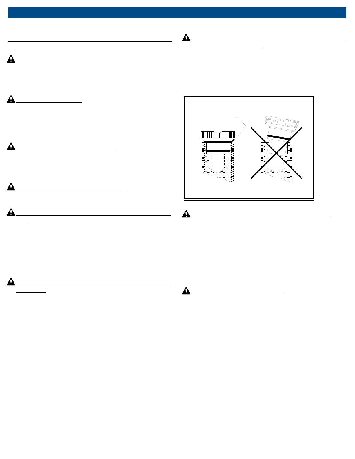
9. Position the lift pad for contact with the vehicle’s lift point.
Check to make sure the lift pad contacts and cradles the
lift point squarely and securely so as to prevent loss of
load.
10. Connect a quick coupler to the air control valve. Close
the release valve by rotating the release knob clockwise.
Attachairsupplyof 90psiminimumto200psimaximum.
The unit is now ready for use. Actuation of the air control
lever will now raise the lift pad. Rotating the release knob
counterclockwise will lower the lift pad (always rotate this
knob slowly and only rotate the knob as far as necessary
to lower the vehicle gently).
11. Raise the load to the desired height. Upon actuating the
air control valve, the jack lift pad will rise quickly until
contact is made with the load. Then the jack will continue
to lift the load (at a slower rate) until the air control valve
is released or the jack has reached the limit of its stroke.
12. Position appropriate support stands under the vehicle
manufacturer’s recommended lift areas to provide stable
support for the raised vehicle. Make sure all personnel
are clear of the area.
13. Lower the vehicle onto the support stands by slowly and
carefully turning the release control knob
counterclockwise. When lowering the jack, it is important
to keep the rate of lowering under control and to assure
the recommended vehicle lift points will properly rest on
the stand pad. Refer to the instructions and warnings
accompanying the support stands for additional
information about their safe use.
14. When the support stands are supporting the entire load,
the jack can be removed from the area before work on
the vehicle begins.

CAJ-25LP | 9|en
Operation
7.2 Lowering a vehicle
1. Make sure the vehicle load does not exceed the rated
capacity of the jack (50,000 lbs. / 22,680 kg.)
2. Inspect the jack for signs of wear or damage (see
“Inspection Instructions” in Section 8). The jack should
be immediately removed from service if you detect any
abnormal conditions or signs of damage that suggest
the jack will not work properly or safely —When in
doubt, don’t use the jack!
3. Transport the jack to the work area by wheeling it. You
can push or pull the jack. Wheel the jack across smooth
surfaces only.
4. Close the release knob by rotating clockwise and
actuate the control valve to raise the vehicle off the
vehicle support stands.
5. Carefully remove the vehicle support stands from
beneath the vehicle and place them awayfrom the work
area.
6. Slowly turn the release knob counterclockwise to lower
the vehicle to the floor gently. The ram will fully retract
by leaving the air supply connected and the release
valve open. Theram will fully retract evenunder no-load
conditions.
7. Lower the jack completely and move the jack and
chocks away from the work area.

en | 10 |CAJ-25LP
Maintenance and Inspection
8. Maintenance and Inspection
mWARNING - The jack must be inspected according to
the requirements of this section. Failure to properly
inspect the jack could lead to severe injury or death.
The jack must be removed from service and inspected
immediately if it is subjected to an abnormal load or a
shock load. If any irregularities or problems are
detected during an inspection, the jack must be
removed from service immediately and repaired.
Contact the manufacturer at the numbers and address
printed on the back cover of this manual.
8.1 Inspection –before each use
Visual inspection of the jack must be made before each
use of the jack. The jack should be immediately removed
from service if any of the following conditions are detected
or observed:
The lift pad or extended lift pad is cracked, chipped, or
shows signs of excessive wear.
The ram shows signs of damage such as bends, twists,
cracks, chips, corrosion, misuse, or excessive wear.
The jack’s controls or wheels do not operate smoothly
or freely.
An oil leak is observed.
Any abnormal condition or sign of damage that
suggests the jack will not work properly.
8.2 Inspection –periodic
The jack owner (or a knowledgeable person appointed by
the owner) must give the jack a more thorough inspection
weekly (if it is used on a daily basis) or monthly (if used
less frequently). In addition to a visual inspection (as
described above), the inspector should also operate and
move the jack to assist in identifying any problems that
might exist. The jack must be removed from service and
repaired if the jack appears damaged, if it is badly worn, or
if it operates abnormally.
Inspect lift pad and extended lift pad and remove jack
from service if either lift pad is cracked, chipped, or
shows signs of excessive wear.
Raise and lower the ram to ensure it moves smoothly
through its full range. Inspect the ram for damage such
as bends, twists, cracks, chips, corrosion, misuse, or
excessive wear.
Move the jack forward and backward on its wheels to
ensure that the wheels rotate smoothly and freely.
Inspect for oil leaks. If oil leaks occur, refer to the
“Troubleshooting” section of this manual.

CAJ-25LP | 11 |en
Maintenance and Inspection
8.3 Maintenance instructions
mWARNING - All inspection and maintenance procedures
must be performed after the jack has been removed from
service.Failuretodothismayresultinpersonalinjuryand/or
propertydamage.
All warning and capacity labels should be readable and
complete. Wash external surfaces of jack, labels, and
decals with a mild soap solution.
Lubricate all rotating and sliding portions of the jack
monthly.
8.4 Adding hydraulic fluid
mWARNING - The oil reservoir in this equipment is
sealed and pressurized when in use. When checking
the fluid level, do not have the jack connected to the air
supply. Failure to heed this warning may result in
personal injury and/or property damage.
1. Remove the jack from service.
2. Disconnect the air line.
3. The ram must be in the fully-lowered position and the
jack must be on a level surface.
4. Carefully remove the plastic cover from the oil reservoir
plug located on the top surface of the jack body.
5. Clean around the surface of the oil fill plug to prevent
contamination of the hydraulic oil system.
6. Remove the oil fill plug using a 3/16 Hex wrench.
7. Visually check the hydraulic oil level. RAM MUST BE
FULLY RETRACTED. The oil should be within 1/4 inch
of the bottom of the oil fill hole. If the fluid level is low,
add a high-grade hydraulic fluid equivalent to Mobile
Tellus T22 oil.
mCAUTION - Do not use brake or transmission fluid. Use
of the wrong fluid can deteriorate the seals and
corrosion problems will occur.
8. Reinstall and secure the oil reservoir plug, replace the
plastic cover, and connect to air supply and test for
normal operation.
9. Troubleshooting
This section is a list of potential problems and solutions. If
the solution listed fails to correct the problem, call the
manufacturer at the numbers and address printed on the
back cover of this manual. Please have the model number,
and serial number of your jack available. The serial
number is permanently stamped on a metal tag attached
to the top of the frame.
Problem
Cause/Solution
Fails to lift load
•Low oil level; see the “Adding Hydraulic
Fluid” section.
•Inadequate air pressure; ensure 90 psi
minimum.
•Release open; turn release knob
clockwise until tight.
•Airline leaks; locate and correct leaks.
•Overloaded; use larger-capacity jack.
Fails to hold load
•Release open, turn release knob
clockwise until tight.
Air motor will not run
•Airline leaks; locate and correct leaks.
•Inadequate air pressure; ensure 90 psi
minimum.
•Air piston sticking or stuck, add oil to air
inlet to lubricate piston.
Oil leaks
•Oil reservoir plug loose; tighten oil
reservoir plug.

en | 12 |CAJ-25LP
Maintenance Chart
10. Maintenance Chart
Action
Date
Details
Person
responsible
Receiving inspection

CAJ-25LP | 13 |en
Maintenance Chart
Action
Date
Details
Person
responsible

en | 14 |CAJ-25LP
Notes
11. Notes

CAJ-25LP | 15 |en
Notes

en | 16 |TSL-50
MAHLE Aftermarket Inc.
916A West State Street
St. Johns, Michigan 48879-1404 U.S.A.
Phone: (800) 468-2321
www.servicesolutions.mahle.com
670-90707_A
Table of contents
Other MAHLE Lifting System manuals
Popular Lifting System manuals by other brands

Simon, Evers & Co
Simon, Evers & Co K 658791 operating manual

WIRTH
WIRTH OKTOPUS GLASS-Jack GL-CC 1200 operating instructions

Garage Smart
Garage Smart MY LIFTER BASIC LIFTER manual

Ravas
Ravas iForks user manual

Smart Lift
Smart Lift SL 400 Skylifter instruction manual

ServerLIFT
ServerLIFT SL-350X Operator's manual

Pride Mobility
Pride Mobility LC-125 quick start guide

Ravas
Ravas iForks Service manual

Basta Boatlifts
Basta Boatlifts Over-Center 24k60 Assembly & installation

Rothewald
Rothewald 10059174 Assembly and operating instructions

Challenger Lifts
Challenger Lifts 40200 Operation installation maintenance manual

Faraone
Faraone ELEVAH 70 Use and maintenance instructions