MAHLE CAD-FL User manual

MAHLE CAD-FL & CAD-FL3
EN
Operation Manual
CML Forklift adapter

EVERY PERSON WHO OPERATES THIS
EQUIPMENT NEEDS TO KNOW AND
UNDERSTAND ALL OF THE INFORMATION IN
THIS MANUAL – FAILURE TO DO SO COULD
RESULT IN SERIOUS INJURY OR DEATH.
READ THIS MANUAL
CAREFULLY AND
RETAIN FOR YOUR
RECORDS

CAD-FL & CAD-FL3 |3|en
Contents
Contents
1. Safety Regulations ..................................................4
1.1 Safety Instructions .......................................4
2. Foreword..................................................................5
2.1 From the manufacturer.....................................5
3. Symbols Use............................................................5
3.1 Signal words ....................................................5
4. Responsibilities .......................................................6
4.1 Receiving inspection.........................................6
4.2 Owner and/or operator responsibilities .............6
5. Specifications..........................................................6
6. Component Identification………………………...….…..7
7. Operation.................................................................8
7.1 Installation Instructions.....................................8
8. Structural Inspection……………………………………10
9. Notes......................................................................11

en |4|CAD-FL & CAD-FL3
1. Safety Regulations
1.1 Safety Instructions
To avoidseriousinjury or death, readthis manualcarefully
before installing and using the forklift adapter system.
Contact the manufacturer if you have any questions.
Failure to understand and obey safety instructions may
result in unsafe or improper use of this product.
NEVER exceed capacity. Maximum system
capacity is 15,000 lbs. / 6,804kg.
ALWAYS use this forklift adapter only on hard
level surfaces capable of sustaining the load.
Use on other than hard level surfaces can
result in instability and possible loss of load.
NEVER lift anything other than forklifts. This
forklift adapter system is designed solely for
the lifting of forklifts.
NEVER make alterations to this product.
ALWAYS lift with the factory supplied lift
platforms in place. Do not attempt to use any
other part of the forklift adapter system as a
lifting point. Do not use any kind of cribbing
or adapters with this forklift adapter system.
The lifts that the system is mounted on must
be lowered to the ground and remain in direct
contact with the floor, and the forklift adapter
lift platforms must be in direct contact with the
vehicle.
ALWAYS ensure that all parts of the adapter
are lined up properly.
ALWAYS place the forklift center of gravity in
the center of the lifting platforms attached to
the lift carriage.
ALWAYS ensure that the weight center is
balanced front to back and the lifting
platforms are fully engaged under the forklift
before lifting higher that 2”.
ALWAYS lift the vehicle using the vehicle
manufacturer’s recommended lift points. The
lift point must be strong enough to sustain the
lifting force without damage to the vehicle.
NEVER place hand or any other body part
between lift platform and vehicle, personal
injury can occur.
NEVER lift a forklift by the counterweight.
NEVER rock a forklift after it is higher than 4"
in the air.
NEVER lift a forklift unless both lift platforms
are at least 6" under the sides of the forklift.
NEVER lift a forklift if the underside which
contacts the lift platform is not completely flat.
NEVER lift a forklift if the counterweight, mast
or batteries have been removed. The vehicle
weight center will be severely affected.
NEVER use the 3 wheel adapter without the
Lateral Support Bar properly placed.
Failure to understand and obey this warning may
result in personal injury and / or property damage.

CAD-FL & CAD-FL3 |5|en
2. Foreword
2.1 From the manufacturer
Thank you for your purchase. To complement the offering
of A/C, fluid and nitrogen service equipment, MAHLE
Service Solutions has partnered with GrayManufacturing
to provide the highest quality hydraulic and pneumatic
equipment available for the professional service
technician. This equipment adheres to high standards
promised in the MAHLE guarantee including the
assuranceof innovation andreliability that comes with the
Gray Manufacturing name. Please contact MAHLE
Service Solutions’ customer service at (800) 468-2321 or
tech.mss@us.mahle.com with any comments or
questions.
3. Symbols Use
3.1 Signal words
Signal words call attention to a safety message or
messages, or a property damage message or messages,
and designate a degree or level of hazard seriousness.
Signal words used in this manual include:
Keyword Probability of
occurrence
Severity of danger if
instructions not
observed
DANGER Immediate
impending danger
Death or severe injury.
WARNING
Possible impending
danger
Death or severe injury
CAUTION
Possible dangerous
situation
Minor injury
NOTICE
Possible damage to
property
Possible property
damage

en |6|CAD-FL & CAD-FL3
4. Responsibilities
4.1 Receiving inspection
Before attempting to operate this equipment, thoroughly
read and understand this manual. Completely remove all
tape and packaging. Inspect the equipment immediately
upon delivery. If shipping damage is evident, inform the
delivering carrier immediately and contact the
manufacturer using the contact information on the back
cover of this manual.
4.2 Owner and/or operator responsibilities
The owner of this equipment must read these instructions
and maintain them for future reference and for instructing
any other users of the equipment. The owner is
responsible for keeping all warning labels and instruction
manuals legible and intact. Replacement labels and
literature are available from the manufacturer. The owner
must never authorize or allow anyone to use this
equipmentuntil the operator hasreadandunderstoodthe
information in this manual and on the accompanying
labeling on the equipment itself.
If this equipment is being used in an occupational setting
(or workplace), the employer should ensure that all
personnel working with and around the equipment know
of the risks associated with its use. Personnel involved in
the use and operation of this equipment shall be careful,
competent, trained, and qualified in the safe operation of
the equipment and its proper use when servicing motor
vehicles and their components. Safety information
provided with this equipment should be emphasized by
the employer and understood by each employee. The
employermustmake this manualavailable toallpersonnel
using this equipment and all personnel must read and
understand the contents of this manual. If the operator is
not fluent in English, the manufacturer’s instructions and
warnings shallbe readto and discussedwith the operator
in the operator’snative language bythe employer, making
sure that the operator comprehends its contents and
observes the proper procedures for use ofthis equipment.
5. Specifications
Model CAD-FL & FL3 US units Metric units
System Capacity 15,000 lbs. 6803.9 kg
Maximum Lift Height 68 in 26.8 cm
System height 12 in 4.7 cm
Level System Length 81 3/4 in 32.2 cm
Ramp Length 50 3/8 in 19.8 cm
System Weight 682 lbs. 309.4 kg
System Weight with 3 Wheel
Option 883 lbs. 400.5 kg

CAD-FL & CAD-FL3 |7|en
6. Component Identification

en |8|CAD-FL & CAD-FL3
Channel
Frequency
Confirm
Frequency
Channel
100
Please select and confirmthe
desired radio settings for this
lift.
1
2
1
CurrentLocation:
Enter theLift's
position by touching
the corresponding
location button.
7. Operation
7.1 Installation Instructions
The adapter components are heavy and will require two
people to handle. If using a lift system that has a different
operating system than referred to in this manual, consult
the manual supplied with the lift system for information on
setting up and operating the lifts.
1. Make sure the master on/off switch on each lift
unit is set to the OFF position. Turn the master
on/off switch on the first lift unit to the ON position
(see the lift system owner’s manual for loc ation of
the master on/offswitch).The Home screen willbe
shown with a series of icons on the screen. Select
the Lift Program icon to start the program used to
lift a vehicle. After initialization of the Touch
Screen, the below screen will be displayed.
2. Selectthe desiredradio settings. The defaultradio
settings will be the settings selected the last time
the unit was used. Push the up and down arrows
on the right side of the screen to change the radio
frequency and/or channel, if needed. All units that
will be usedtogether as a lift systemto lift a vehicle
must be set to the same frequency and channel.
When the desired radio settings are shown, push
the Confirm button to advance to the next screen.
3. Read through the Notice that is displayed on the
next screen. If the operator agrees with and
acknowledgesthe statements made onthe screen
push the Accept button to continue setting up the
lift system.
4. The display then changes to ask how many lift
units are going to be part of the lift system. Push
the 2 button to set the lifts up as a set of two.
5. On the following screen, choose Forklift Adapter
Mode in order to raise the set of two lifts full height.
WARNING! Only use Forklift Adapter Mode with a
manufacturer supplied forklift adapter.
6. The display will now appear as shown below with
a picture of a vehicle asking for the current lift
unit’s position relative to the vehicle. Select the
round button with a number inside it that matches
the current lift unit’s position. Once the position is
selected the position button will turn green to
indicate the selection.
7. Now move to the second lift unit and turn the
master on/off switch to the
ON
position. The
same screen shown in Step (1) above will
appear.
Select the same radio frequency and channel as was
chosen in Step (2) above by pushing the up and down
arrows on the right side of the screen. When the correct
radio settings are shown, push the Confirm button.
8. The display will now show the same screen as
shown in Step (6) above. Select the round
button that matches the position of the current
lift unit relative to the vehicle. The position that
has already been selected will be shown by a
yellow colored button.
9. Once both units are initialized (radio settings
and position relative to the vehicle selected)
the lifts will be ready to operate.
10. Raise the Lift Carriagesabout10inchesandinstall
the Lift Platforms as shown in the figure below.
Ensure the guide pin is fully inserted into the
correct hole on each lift arm. The lift arms must be
adjusted such that they are the correct width to
properly accept the forklift adapter.

CAD-FL & CAD-FL3 |9|en
Lift Platform Tab
Carriage Slot
WheelTread
Center Lines
Optional3 WheelAdapter
Lift Platforms
Tire Support Platforms
with Chocks
11. Align the lift units so that they will be as shown in
the figure below when the Forklift Adapter is fully
assembled. Ensure that they are directly across
from each other. If the optional 3 Wheel Adapter
(shown) is used, it must be centered between the
outside ramps.
12. Adjust the distance between lift units until the
center lines of the ramps and tire supports will be
the same as the center to center tread
measurement on the forklift to be lifted as shown
in the figure below. After adjusting, lower the base
of each lift unit to the ground. Ensure the lifts and
adapters are properly aligned. If the 3 Wheel
Adapter is to be used, this distance may need to
be adjusted slightly to accommodate the Lateral
Support Bar.
13. With the Lift Carriages raised, install the four Tire
Supports as shown in the figure below. The Tire
Support Platform must set on the lift unit’s base
leg and the front wheelmustprotrude fromthe Tire
Support Platform such that the platform is retained
on the base of the lift unit. If the optional 3 Wheel
Adapter is to be used, ensure that the brackets on
the 3 Wheel Adapter capture the lift units’ base
legs.
14. Install the ramps as shown in the figure below.
Ensure that the Ramp Attachment Hooks are fully
inserted into the Tire Support Ramp Hook Holes
and the ramps are able to contact the floor.

en |10 |CAD-FL & CAD-FL3
Lateral Support Bar
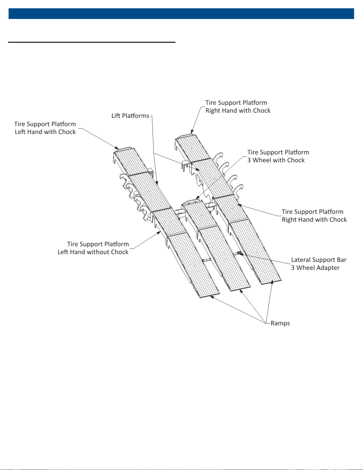
15. If the 3 wheel adapter is to be used, align the tabs
on the Lateral Support Bar with the ramps and
slide it back as far as possible. All three ramps
must be captured by the Lateral Support Bar.
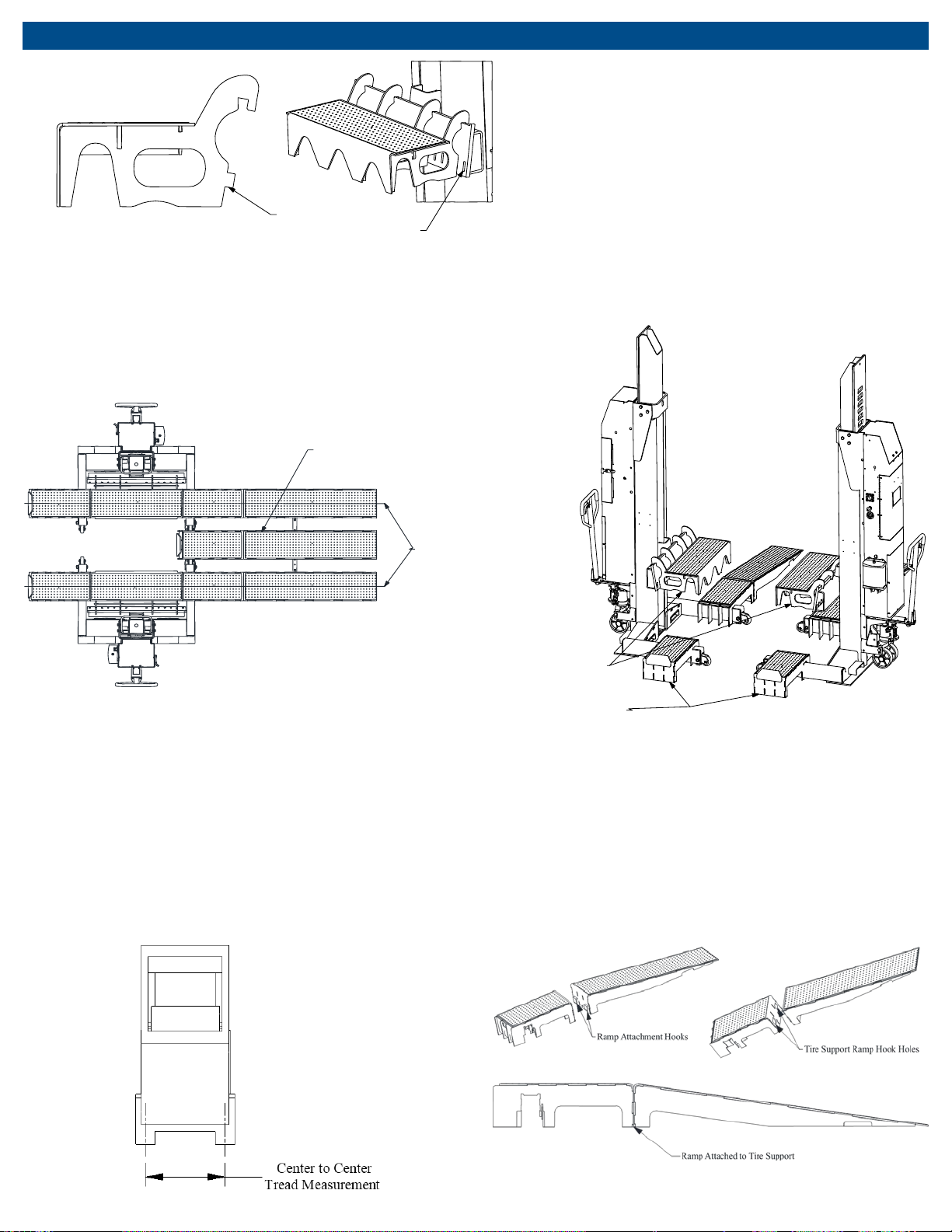
16. Lower the Lift Carriages completely and verify
correctalignmentofthe platforms.Backthe forklift
up the ramps only if using a 4 wheel forklift. If using
the optional 3 Wheel Adapter with a 3 wheel
forklift, pull onto the ramps forward. It is
necessary to have a spotter in order to keep the
forklift tirescenteredon the ramps andtire support
platforms. Position the forklift front to back so that
the center of gravity of the forklift is as close to
centered on the lift platforms as possible. The
center of gravity of the forklift must be within the
ends of the Lift Platform. Raise the forklift until the
tires are off the tire support platforms 2 inches.
Rock the forklift front to back to make sure it is
stable and can be lifted safely.
17. Once the check is made in step 17 above and the
forklift is stable, the forklift can be raised. Not
ensuring that the forklift is stable can result in loss
of load, which can result in personal injury and/or
property damage.
8. Structural Inspection
WARNING
Equipment must be removed from service and inspected
for damage immediately if subjected to an abnormal
shock or load. Failure to heed this warning may result in
personal injury and / or property damage.
WARNING
It is critical thateach piece ofthe adapter andeach liftunit
be inspected regularly for any signs of wear or damage
that might affect its ability to perform lifts safely. Any
equipment that appears to be damaged in any way, is
found to be badly worn, or operates abnormally must be
removed from service until necessary repairs are made.
Contact the manufacturer if you need to have equipment
serviced or if you have any questions about how to
address any wear or damage observedon the equipment.
The employer, owner, and/or manager are responsible for
maintaining the forklift adapter system and lift units in
good, serviceable condition. Employees must be trained
on how to inspect the equipment. Before each use of a
lift unit, the operator must visually inspect the lift unit for
any abnormal conditions. Any equipment subjected to an
abnormal load or shock must be immediately removed
from service and given a thorough inspection. The
employer, owner, and/or manager must inspect (or
appoint a knowledgeable personto inspect) all equipment
regularly. Regular inspections should be made weekly (if
the equipment is used daily) or monthly (if the equipment
is used only intermittently). Regular inspections should
include the following:
•Check for any visual cracks, chips or other signs
of excessive wear on all pieces of the adapter and
all lift units.
•Raise and lower the lift carriage of each lift unit
through its full range (up and down)—it should
move smoothly. If the lift stutters when lowering
(i.e., it moves in a jerky fashion) the slide pads may
need to be re-lubricated. Refer to the lift system
manual.
•Inspect the slide pad or roller contact surfaces for
damage, such as gouging, warping, etc.
•All controls should operate smoothly and freely.
Inspect the lift units for oil leaks. If oil leaks occur,
investigate and correct the source of the leakage
(refer to the lift system manual). WARNING! Clean up
any oil leakage immediately. Oil left on the floor can
create a slipping hazard.
•Inspect the down stop catch pawl to make certain
it rotates forwardandbackwardfreely. If the catch
pawl does not move freely it may need to be
greased. Refer to the lift system manual.
•Check the positioning of the down stop catch
pawl. Refer to the lift system manual.
If you are not sure whether any identified wear or damage
is “serious”, DO NOT use the equipment. The time it takes
to determine whether or not the problem is “serious”or to
repair the problem is small compared to the time it will
take to deal with the consequences of a lost load (which
could include severe injury or death to personnel).
For more information about the lift units, refer to the
manual that was furnished with the lift units.

CAD-FL & CAD-FL3 |11 |en
9. Notes

MAHLE Aftermarket Inc.
916A West State Street
St. Johns, Michigan 48879
-1401 U.S.A.
Phone: (800) 468
-2321
E
-mail: tech.mss@us.mahle.com
www.servicesolutions.mahle.com
670-90884_A
This manual suits for next models
1
Table of contents
Other MAHLE Lifting System manuals
Popular Lifting System manuals by other brands

ABACO MACHINES
ABACO MACHINES AVL480 Operation manual

stertil-KONI
stertil-KONI ST1075-FBF Installation, operation and maintanance instructions

HALDER
HALDER 22353.1024 manual

CRH
CRH Leviat Halfen DEHA KKT-E Assembly instructions

Blitz
Blitz MRG25-4 Operation & maintenance manual

EAE
EAE EE-612FE Installation, operation, and parts manual

Amico
Amico GoLift Portable450 Installation and operation instructions

Vancare
Vancare VERA-LIFT II B350 operating manual

Waltco Lift
Waltco Lift BZ-33 owner's manual

Grabo
Grabo PRO-LIFTER 20 Operator's manual

Kessel
Kessel Aqualift S Compact Installation and operating instructions

IDEAL
IDEAL 7000TLX Assembly & operation manual