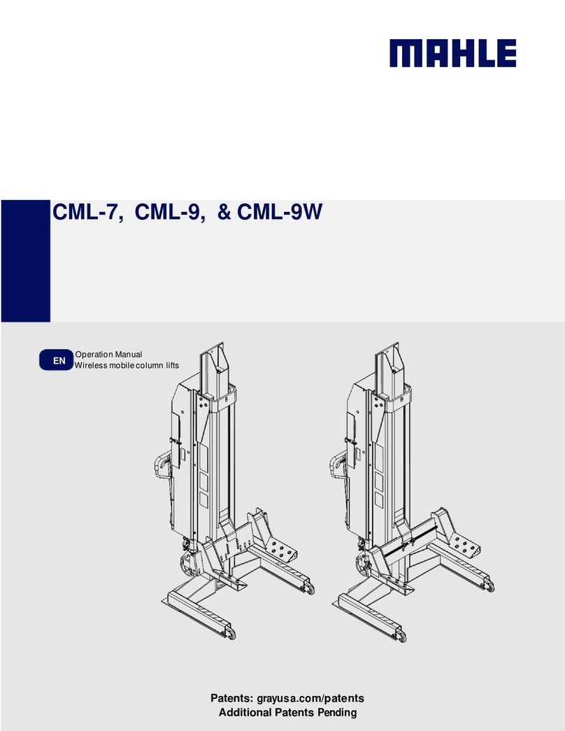
MAHLE CAL-10 User manual

MAHLE CAL-10
EN
Operation Manual
Vehicle Air
Lift

en
|
2
|
CAL
-
10
EVERY PERSON WHO OPERATES THIS
EQUIPMENT NEEDS TO KNOW AND
UNDERSTAND ALL OF THE INFORMATION IN
THIS MANUAL – FAILURE TO DO SO COULD
RESULT IN SERIOUS INJURY OR DEATH.
READ THIS MANUAL
CAREFULLY AND
RETAIN FOR YOUR
RECORDS

CAL
-
10
|
3
|
en
Contents
Contents
1. Safety Regulations ................................................ 4
1.1 Warnings ....................................................... 4
2. Fore ord ................................................................ 5
2.1 From the manufacturer ................................. 5
3. Symbols Use .......................................................... 5
3.1 Signal ords ................................................. 5
4. Responsibilities ..................................................... 6
4.1 Receiving inspection ..................................... 6
4.2 O ner and/or operator responsibilities ......... 6
5. Specifications ........................................................ 6
5.1 CAL-10.......................................................... 6
6. Product Description .............................................. 7
6.1 Component identification .............................. 7
7. Operation ............................................................... 8
7.1 Preparing to lift.............................................. 8
7.2 Operating the air valve to raise a load ........... 8
7.3 Function and purpose of lift .......................... 9
7.4 Moving and positioning the lift ...................... 9
7.5 Adjusting saddle horn height......................... 9
7.6 Lo ering the load ......................................... 9
7.7 Lifting a trailer ............................................. 10
8. Maintenance and Inspection .............................. 11
8.1 Inspection – before each use ...................... 11
8.2 Inspection – structural ................................. 11
8.3 Maintenance instructions ............................ 12
8.4 Air valve cleaning instruction ....................... 12
9. Troubleshooting .................................................. 12
10. Air Pressure Requirements ................................. 12
11. Maintenance Chart .............................................. 13
12. Notes .................................................................... 15

en
|
4
|
CAL
-
10
Safety Regulations
. Safety Regulations
. Warnings
Failure to follo all of these safety instructions can
lead to severe injury or death from a sudden loss of
the load. Contact the manufacturer at the numbers or
address printed on the back cover of this manual if
you have any questions.
Anyone ho operates this jack must read and
understand all the instructions and arnings
provided ith this jack before being allo ed to use
it. All operators must be careful, competent, trained,
and qualified in the safe operation of the jack. The
o ner (or other responsible individual) must ensure
that any operator observes the proper safety
procedures for using this jack at all times. If the
operator does not read ell or is not fluent in English,
the o ner / manager must read and revie the
instructions and arnings in the manual ith the
operator in the operator's native language to be sure
that the operator ill use the jack properly.
The o ner / manager must keep this manual for
future reference, and make sure the arning labels
on the jack are legible and intact at all times.
Replacement labels and manuals are available from
the manufacturer. Call the manufacturer using the
contact information on the back cover of this manual
if you have any questions.
If there is any evidence of hydraulic oil leaking
from underneath this lift, the lift must be removed
from service and returned to the manufacturer for
servicing. Contact the manufacturer as soon as
possible. If this arning is not heeded, it may result in
possible serious injury and/or property damage or
death.
Use the jack to raise one end of a vehicle or trailer.
This jack is designed to for lifting only one end of the
vehicle or trailer, not supporting. Once the vehicle or
trailer is lifted, place vehicle supports stands under
the vehicle or trailer and remove the jack from the
ork area. Using this jack to raise loads other than at
the end of the vehicle or trailer can result in serious
injury or death. NEVER use the jack on a vehicle hile
the motor is running.
NEVER use this jack in conjunction ith any other
jack or lift. NEVER use a jack to raise one side of a
vehicle.
ONLY use the approved manufacturer’s
recommended lifting points on vehicles and trailers.
NEVER overload this jack. The jack’s maximum
capacity is 20,000 lbs. / 9070 kg. If you need to lift
more than this, use a jack that has a higher maximum
capacity.
NEVER modify the jack in any ay. Modifications
may cause the jack to perform improperly, resulting in
injury or death. NEVER use the jack ith aftermarket
accessories, lift pads, or adaptors, not supplied by
the manufacturer.
NEVER loosen the hex nut on top of this jack. This
nut, if loosened ill cause the jack to leak air and not
function properly.
NEVER abuse or cause damage to the jack. NEVER
subject the jack to abnormal shocks or loads. Your
safety and that of others depends on the proper
operation of the jack.
When raising the load, chock the heels on the
end opposite the jack. Place the jack into position,
put vehicle in neutral, and disengage the parking
brake. These steps must be taken before connecting
the air supply to the jack.

CAL
-
10
|
5
|
en
Fore ord
2. Foreword
2. From the manufacturer
Thank you for your purchase. To complement the
offering of A/C, fluid and nitrogen service equipment,
MAHLE Service Solutions has partnered ith Gray
Manufacturing to provide the highest quality hydraulic
and pneumatic equipment available for the professional
service technician. This equipment adheres to high
standards promised in the MAHLE guarantee including
the assurance of innovation and reliability that comes
ith the Gray Manufacturing name. Please contact
MAHLE Service Solutions’ customer service at (800)
comments or questions.
3. Symbols Use
3. Signal words
Signal ords call attention to a safety message or
messages, or a property damage message or messages,
and designate a degree or level of hazard seriousness.
Signal ords used in this manual include:
Key ord Probability of
occurrence
Severity of danger if
instructions not observed
DANGER
Immediate
impending danger
Death
or
severe
injury.
WARNING Possible
impending
danger
Death
or
severe
injury
CAUTION
Possible
dangerous
situation
Minor
injury
NOTICE
Possible
damage to
property
Possible property
damage

en
|
6
|
CAL
-
10
Responsibilities
4. Responsibilities
4. Receiving inspection
Before attempting to operate this equipment, thoroughly
read and understand this manual. Completely remove all
tape and packaging. Inspect the equipment immediately
upon delivery. If shipping damage is evident, inform the
delivering carrier immediately and contact the
manufacturer using the contact information on the back
cover of this manual.
4.2 Owner and/or operator responsibilities
The o ner of this equipment must read these
instructions and maintain them for future reference and
for instructing any other users of the equipment. The
o ner is responsible for keeping all arning labels and
instruction manuals legible and intact. Replacement
labels and literature are available from the manufacturer.
The o ner must never authorize or allo anyone to use
this equipment until the operator has read and
understood the information in this manual and on the
accompanying labeling on the equipment itself.
If this equipment is being used in an occupational setting
(or orkplace), the employer should ensure that all
personnel orking ith and around the equipment kno
of the risks associated ith its use. Personnel involved in
the use and operation of this equipment shall be careful,
competent, trained, and qualified in the safe operation of
the equipment and its proper use hen servicing motor
vehicles and their components. Safety information
provided ith this equipment should be emphasized by
the employer and understood by each employee. The
employer must make this manual available to all
personnel using this equipment and all personnel must
read and understand the contents of this manual. If the
operator is not fluent in English, the manufacturer’s
instructions and arnings shall be read to and discussed
ith the operator in the operator’s native language by
the employer, making sure that the operator
comprehends its contents and observes the proper
procedures for use of this equipment.
5. Specifications
5. CAL- 0
Model CAL-10 US units Metric units
Maximum capacity 20000 lbs 9070 kg
Maximum air pressure 200 PSI 13.8 Bar
Weight 748 lbs 339.3 kg
Width 37 in 94.0 cm
Depth 43 in 109.2 cm
Height (Lo ered) 64 in 162.6 cm
Height (Raised) 94 in 238.8 cm
Saddle spread (Minimum) 37.25 in 94.6 cm
Saddle spread (Maximum) 48.625 in 123.5 cm
Saddle Starting Height
(minimum) 14 in 35.6 cm
Saddle Starting Height
(maximum) 20 in 50.8 cm
Po ered Stroke 30 in 76.2 cm

CAL
-
10
|
7
|
en
Product Description
6. Product Description
6. Component identification
Fig. 1: Side view
1Base
2Air cylinder
3Cylinder head plate
4Pneumatic wheel
5Swivel caster
Fig. 2: Rear view
1Valve handle
2Valve cover
3Handle rip
4Downstpp release lever
5Saddle
6Table extension
7Saddle pin

en
|
8
|
CAL
-
10
Operation
7. Operation
WARNING - This section discusses the appropriate and
safe methods for using the jack to raise and lo er a
vehicle. Safe operation is not limited to simply raising
and lo ering a vehicle - it also includes adequate
preparation before the vehicle is lifted. Failure to follo
all of the steps outlined in this section could result in
serious injury or death.
7. Preparing to lift
1. Make sure the load does not exceed the rated capacity
of the jack (20,000 lbs. / 9,070 kg.)
2. Inspect the jack for signs of ear or damage (see
“Inspection Instructions” in Section 8). The jack should
be immediately removed from service if you detect any
abnormal conditions or signs of damage that suggest
the jack ill not ork properly or safely — When in
doubt, don’t use the jack!
If you see any signs of ear or damage, or if there is any
indication that the jack is not performing normally,
immediately take it out of service and contact customer
service at the address and number sho n on the back
cover of this manual. NEVER use a jack that appears
damaged in any ay.
3. Transport the jack to the ork area by heeling it. You
can push or pull the jack. Wheel the jack across smooth
surfaces only.
Jolting caused by the heels catching on uneven
surfaces can cause physical strain and personal injury.
4. Select appropriate vehicle support stands and bring them
to the immediate ork area. Follo the instructions
supplied ith the vehicle stands. Use appropriate vehicle
stands to support the load immediately after lifting.
NEVER use the jack to support a load hile orking on a
vehicle. Failure to follo all of these instructions can result
in jack instability and loss of a load.
5. Examine the ork area. Use the jack only on hard, level
surfaces capable of safely supporting the load. The jack
must ALWAYS remain in direct contact ith the floor.
Clear the surrounding area of personnel, tools,
equipment, or any other objects that ould interfere ith
the use of the jack. If these conditions cannot be met,
move the vehicle and jack to an area here the lift can be
performed safely.
6. Chock the vehicle’s heels. When raising a vehicle from
one end, al ays chock the heels that ill remain on
the ground. Make sure at least t o heels of the vehicle
remain in contact ith the floor at all times — NEVER
use the jack to raise all four heels of the vehicle from
the floor.
7.2 Operating the air valve to raise a load
Once the lift has been positioned under the load to be
lifted (according to the safety instructions on the lift),
operate the air valve slo ly to carefully raise the saddles
to engage (capture) the lift points of the vehicle (Fig. 3).
After the saddles make contact ith the lift points,
visually recheck their position to be sure the load is
properly seated for lifting. Be careful not to put any part
of your body (e.g., arms, hands, fingers, etc.) bet een
the saddle and the lift point on the vehicle. When raising
or lo ering, the operator should check to make sure
nobody else is in the immediate ork area.
Fig. 3: Air valve operation
To lo er the lift, it may be necessary to raise the lift slightly
so the do n stop pa l can be disengaged from the do n
stop lug. If lo ering the vehicle on vehicle support stands,
follo the instructions for positioning and supporting the
load outlined in the stand instructions. If lo ering the load
to the ground, make sure that the ork area underneath
the vehicle is clear of obstructions before removing the
vehicle support stands. Disengage the do n stop pa l by
holding the lever hile pressing the air valve to the right
(i.e., the lo er position). Hold in the air valve and do n stop
lever until the lift can be removed from under the vehicle.
Air must bleed off for a fe seconds before the lift ill start
lo ering.
To avoid a crushing injury, you must make sure that no
objects or body parts are on the ground near the lift
platform henever the lift and/or the load are being
lo ered.
These operating instructions are designed to
supplement, not replace, the information and safety
instructions provided on the lift itself.
LIFT CONTROL LEVER
P US H
T O RA I S E
P US H
T O L OWE R
LIFT CONTROL LEVER
PU S H
T O R A I S E
P US H
T O L OW ER
To Raise
To Lower

CAL
-
10
|
9
|
en
Operation
7.3 Function and purpose of lift
This lift is designed to lift loads—it is not designed to
support loads once lifted. Thus, this lift must al ays be
used in conjunction ith appropriate and adequate
vehicle support stands. Also, this lift is designed to lift
certain loads (e.g., vehicles, trailers) in specific ays
(one end and never on the side). NEVER attempt to use
this lift in ays for hich it as not designed. If you have
lifting needs that cannot be met by this lift, do not
attempt to modify the lift or use it for purposes other
than those for hich it as designed—al ays use a
lifting device that is appropriate for the load. Do not use
adapters and / or attachments from other units. Consult
parts list for adapters and/or attachments that can be
used on this product, not to exceed maximum lift height
of 50”. Contact the manufacturer if you have any
questions about other lifts or the appropriateness of this
lift for different types of jobs.
7.4 Moving and positioning the lift
The operator should move this lift only on a hard level
surface. When moving this lift around the shop floor, it
must never be moved in the raised position. When
moving the lift, the lift must al ays be in the lo est
position.
Use only the handles provided as the means by hich
you grab the lift and move it. The lift should NEVER be
tilted back ards for any reason (i.e., to clear an obstacle
on the floor, to move under an elevated obstacle, etc.).
Tilting the lift can cause the lift to fall back ards onto
the operator or someone ho might be nearby. If the lift
ever does fall, for hatever reason, get out of the ay
immediately—NEVER try to catch the lift if it falls
back ards.
7.5 Adjusting saddle horn height
On occasion, it may be necessary to adjust the height of
the saddle horns in order to make good contact ith the
lift points of the load (i.e., if there is a distance bet een
the saddle in the lo est position and the lift point on the
load). The height of the saddle horns can be adjusted by
removing the pin from the saddle, raising the saddle and
reinserting the pin into the hole. The pin should al ays
be placed all the ay through the saddle arm support.
Also, both saddles must be pinned at the same height
hen lifting a load. DO NOT make saddle height
adjustments if these conditions cannot be met. Follo
the safety instructions on the lift for positioning the
saddles on the lift.
7.6 Lowering the load
In lo ering the load, follo steps one (1) through four (4)
as indicated on the Warning Decal. Once the saddles of
the lift have been positioned properly according to these
steps, raise the lift slo ly to lift the load off the vehicle
support stands. Remove the vehicle support stands from
underneath the vehicle. Visually inspect the area beneath
the vehicle to ensure that it is free of any obstructions
before preparing to lo er the vehicle to the ground.
Before operating the air valve (refer to the operating
instructions – “Operating the Air Valve” & Fig. 3), make
sure that no one else is in the immediate ork area.
Disengage the do n stop pa l by holding the air valve
and do n stop lever until the lift can be removed from
under the vehicle. Air must bleed off for a fe seconds
before the lift ill start lo ering. After lo ering the load,
put the vehicle in park and engage the brakes before
removing the jack.

en
|
10
|
CAL
-
10
Operation
7.7 Lifting a trailer
In addition to lifting vehicles, this lift can be used to lift
trailers. It is important that the box or flatbed trailers
be EMPTY prior to lifting to ensure that any eight
imbalance in the load does not cause a tip-over hen
the load is lifted. Also, box and flatbed trailers should
be disconnected from their tractors and should be
resting on their front supports.
Do not lift the trailer by the ICC bumper if the trailer
manufacturer has not designated it as an approved
lifting point. In preparing to lift an EMPTY box or
flatbed trailer, you should inspect the rear ICC
bumper to make sure it is not bent or damaged in any
ay. If this bumper is damaged, consult the
manufacturer to determine if there is an alternate
lifting location. Roll the lift into place; make sure it is
centered in the trailer and bumper. Make sure that the
lift saddles on the lift frame fully engage (cradle) the
bottom of the bumper and that the saddle horns are
positioned front to back to ensure that the bumper is
resting on the face of the saddle and is captured
bet een the saddle horns—this prevents the bumper
from slipping off the saddles hen lifted.
The proper lift points on an ICC bumper are directly
beneath the vehicle structure members (Fig. 4), hich
connect ith the frame and are approximately 34
inches apart in idth. Slo ly raise the lift frame to
engage the bottom of the bumper. Raise the rear of
the trailer to the desired height and then install vehicle
stands of the proper capacity to support the trailer.
Once the stands are in place, lo er the trailer onto
them and then remove the lift from the ork area.
Follo the instructions for lo ering hen ork is
completed.
Fig. 4: Lifting trailer

CAL
-
10
|
11
|
en
Maintenance and Inspection
8. Maintenance and Inspection
WARNING - The jack must be inspected according to
the requirements of this section. Failure to properly
inspect the jack could lead to severe injury or death.
The jack must be removed from service and
inspected immediately if it is subjected to an
abnormal load or a shock load. If any irregularities or
problems are detected during an inspection, the jack
must be removed from service immediately and
repaired. Contact the manufacturer at the numbers
and address printed on the back cover of this manual.
8. Inspection – before each use
Visual inspection of the jack must be made before each
use of the jack. The jack should be immediately removed
from service if any of the follo ing conditions are
detected or observed:
Visually inspect all components of the lift for signs of
corrosion and/or excessive ear.
Inspect the lift for any cracks, chips, or signs of
excessive ear. Visually inspect the elds.
Inspect the saddle support adjusting pins for signs of
excessive ear or deformations. Also, inspect the
holes on the saddle arm for elongation. If pins cannot
be removed from the saddle arms or if there is
elongation of the holes, then it is likely that the lift
has been overloaded and should be taken out of
service until it can be repaired.
Verify that all arning and instructions decals) are in
place and legible before the lift is put back in service.
If any decals are missing or illegible, contact the
manufacturer for replacements.
If there is any evidence of hydraulic oil leaking from
underneath this lift, the lift must be removed for
service and returned to the manufacturer for
servicing. This unit is equipped ith a non-
serviceable vertical restraint and must be returned to
the factory for repair. Contact the manufacturer as
soon as possible.
8.2 Inspection – structural
The o ner must inspect, or appoint a kno ledgeable
person to inspect the jack for signs of corrosion and / or
excessive ear. Visual inspection should be made
before each use of jack, checking for abnormal
conditions. Regular inspections should be made eekly
for daily use and monthly for intermittent use. Each jack
must be inspected immediately if subjected to an
abnormal load or shock. Any jack hich appears to be
damaged in any ay, is found to be badly orn, or
operates abnormally shall be removed from service until
necessary repairs are made.
The jack must be removed from service and
inspected for damage immediately if the jack is
subjected to an abnormal shock or load. Never return
the jack to service until all damaged components
have been properly repaired or replaced. Al ays test
the lift and verify proper operation before returning the
jack to service. Failure to heed this arning may result
in personal and / or property damage.
To prevent serious injury or death from a falling
vehicle, all inspection and maintenance procedures
must be performed after the jack has been removed
from service. Position the lift so you have clear access
to all sides of the lift for inspection and service
Inspect the lift for any cracks, chips, or signs of
excessive ear. Visually inspect the elds.
If any irregularities or problems are detected during an
inspection, the jack must be removed from service
immediately and repaired. Contact the manufacturer
using the contact information on the back cover of
this manual.

en
|
12
|
CAL
-
10
Troubleshooting
8.3 Maintenance instructions
WARNING -
All inspection and maintenance procedures
must be performed after the jack has been removed
from service. Failure to do this may result in personal
injury and/or property damage.
All arning and capacity labels should be readable
and complete. Wash external surfaces of jack, labels,
and decals ith a mild soap solution.
Lubricate all rotating and sliding portions of the jack
monthly.
8.4 Air valve cleaning instruction
1. Remove the valve cover.
2. Remove the valve form the 1/4" pipe nipple.
3. Remove the brass handle in the valve body.
4. Use a stiff ire or pin punch to push the spools out
of the valve body.
5. Carefully examine the seal on the end of the spool for
any dirt or foreign material. If foreign material is
embedded in the seal, remove the scre and cup
from the end of the spool, then remove and clean the
seal. Turn the seal over and reassemble it into the
cup. Secure the cup back onto the end of the spool
ith the scre .
6. Lubricate the spool ith light chassis grease. Insert
the spool ith O-ring into the air inlet spool port.
7. Insert the spool ithout O-ring into the air exhaust
port.
8. Insert the spring(s).
9. Apply thread sealant to the plug(s) and install the
plugs into the valve body. Do not over tighten the
plug(s), as the threads can very easily be damaged.
10. Install the valve back onto the pipe nipple using pipe
thread sealant on the threads of the nipple.
9. Troubleshooting
This section is a list of potential problems and solutions.
If the solution listed fails to correct the problem, call the
manufacturer at the numbers and address printed on the
back cover of this manual. Please have the model
number, and serial number of your jack available. The
serial number is permanently stamped on a metal tag
attached to the top of the frame.
Problem Cause/Solution
Fails to lift load
•Inadequate air pressure; requires 200-psi
to lift 20,000 pounds.
•Lift is overloaded. Rated capacity is for the
jack is 20,000 lbs. per lift. Use other lifting
means.
•
Air valve is dirty or damaged. See the “Air
Valve Cleaning Instructions” section of this
manual.
Lift ill not lo er or
lo ers erratically
•Vehicle parking brake is set and/or
transmission is in gear.
•If lifting on front of vehicle and rear heels
are chocked, place chocks at least 6”
behind heels so vehicle can roll
back ards
Lift raises slo ly
•Lo air pressure. Raise air pressure to 200
psi.
•Air valve is dirty or damaged. See the “Air
Valve Cleaning Instructions” section of this
manual.
•Lifts overloaded. Rated capacity is for the
jack is 20,000 lbs. Use other lifting means.
Lift is erratic hen
lifting or lo ering
•Make sure vehicle is in neutral and baking
brake is disengaged. Al ays chock heels
on opposite end prior to lifting.
0. Air Pressure Requirements
To lift 5,000 pounds requires 70 psi.
To lift 10,000 pounds requires 107 psi.
To lift 15,000 pounds requires 152 psi.
To lift 20, 000 pounds requires 205 psi.

CAL
-
10
|
13
|
en
Maintenance Chart
. Maintenance Chart
Action Date Details Person
responsible
Receiving inspection

en
|
14
|
CAL
-
10
Maintenance Chart
Action Date Details Person
responsible

CAL
-
10
|
15
|
en
Notes
2. Notes

en
|
16
|
TSL
-
50
670
-
907
48
MAHLE Aftermarket Inc.
10 Innovation Drive
York, PA 17402 U.S.A.
Phone: (800) 468-2321
Fax: (717) 755-8304
E-mail: tec[email protected]hle.com
.servicesolutions.mahle.com
Table of contents
Other MAHLE Lifting System manuals
Popular Lifting System manuals by other brands

Aqua Creek
Aqua Creek PATRIOT PORTABLE LIFT Installation and operating instructions

Golf-Lift
Golf-Lift GL-9 Installation and owner's guide

Ravaglioli
Ravaglioli KPH 370.32 Translation of the original instructions

Suspa
Suspa MOVOTEC Series manual

Adam Hall
Adam Hall STAGELIFT 150 user manual

Peak
Peak 409-HPN Installation and service manual

Space
Space SM297H.4 Original instructions

Dannmar
Dannmar D2-10 Series Installation and operation manual

weha
weha SLAB GRAB JUMBO II Operation and service instructions

Nexus 21
Nexus 21 L-27i installation instructions

Nussbaum
Nussbaum TOP LIFT TSK 12000 DJ Operating manual, Inspection book

Ranger
Ranger RFJ-3TQP Assembly and operation manual