5
PRODUCT OVERVIEW
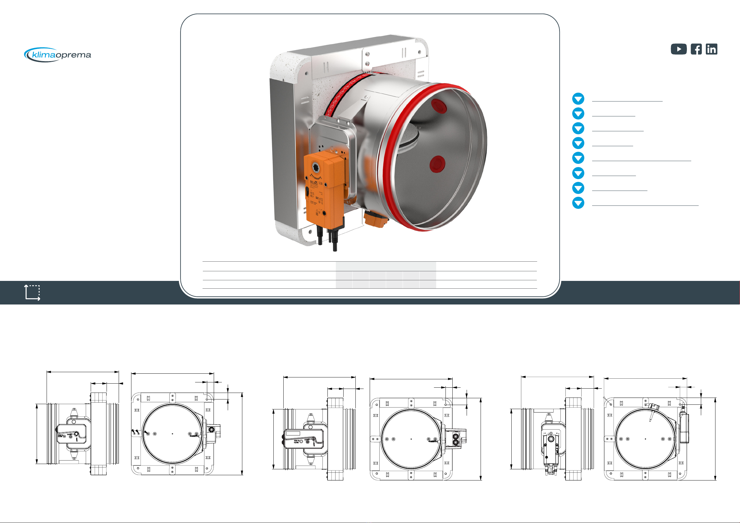
DIMENSIONS
INSTALLATIONS
ACTUATORS
COMMUNICATIONS MODULES
ACCESORIES
REPLACEMENTS
MAINTENANCE AND OPERATION
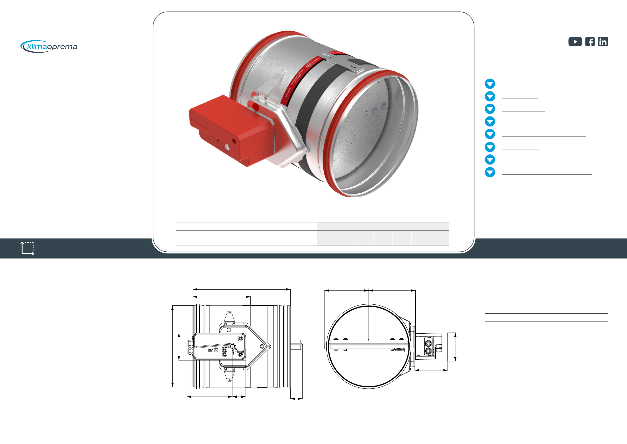
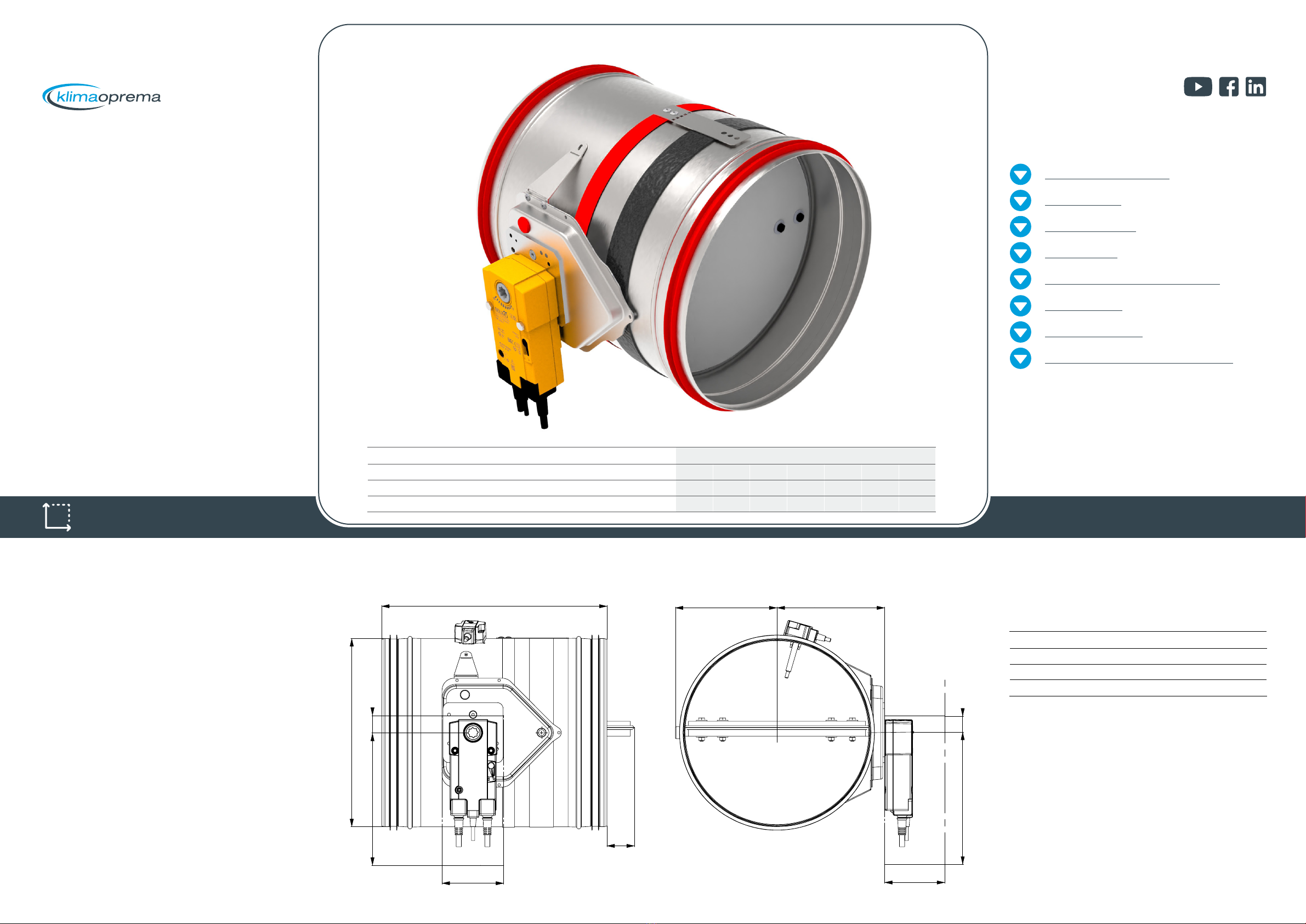
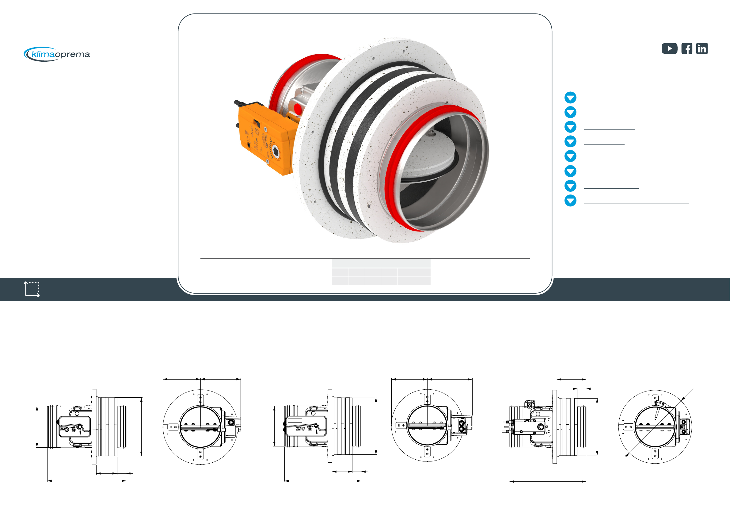
FIRE DAMPER - FDC
MODELS
Casings
Actuators
R (R-S)
Manual operating mechanism, optionally with end switches (R-S). In case
of fire, the fire damper closes automatically. Damper closing can be initiated
either by thermal fuse melting, or by manual activation on the operating
mechanism. Upon closure, damper blade is locked in closed position and
can only be opened manually. Thermal fuse melting point is 72°C.
EMS-S
Electromagnetic operating mechanism, comes with end switches as
standard. In case of fire, the fire damper closes automatically. Damper
closing can be initiated either by thermal fuse melting or remotely by
triggering the electromagnet. Electromagnet is constantly under power and
activates closing of the damper blade in case the power cuts out. Upon
closure, damper blade is locked in closed position and can only be opened
manually. Thermal fuse melting point is 72°C.
M230-S
Belimo 230V electro motor operating mechanism, comes with integrated
end switches. In case of fire, the fire damper closes automatically.
Damper closing can be initiated either by thermal fuse melting or remotely
by triggering the electro motor. Upon closure, damper blade is locked in
closed position and can be opened by sending a signal to electro motor.
Thermal fuse melting point is 72°C.
M24-S
Belimo 24V electro motor operating mechanism, comes with integrated
end switches. In case of fire, the fire damper closes automatically.
Damper closing can be initiated either by thermal fuse melting or remotely
by triggering the electro motor. Upon closure, damper blade is locked in
closed position and can be opened by sending a signal to electro motor.
Thermal fuse melting point is 72°C.
M24-S-ST
Belimo 24V electro motor operating mechanism, comes with integrated
end switches. In case of fire, the fire damper closes automatically.
Damper closing can be initiated either by thermal fuse melting or remotely
by triggering the electro motor. Upon closure, damper blade is locked in
closed position and can be opened by sending a signal to electro motor.
Thermal fuse melting point is 72°C.
Actuator is additionally equipped with connection socket for easy
connection with power supply and communication modules.
EX
ATEX rated fire dampers are equipped with Schischek ExMax actuators,
Exbox-TT thermal switches and ExBox plenum boxes.
Optionaly casing can be produced in AISI316L stainless steel.
Ordering key
FDC25
Cylindrical fire damper with 25mm damper blade and
fire classification up to EI120S. Sizes range from d100
till d315.
FDC40
Cylindrical fire damper with 40mm damper blade and
fire classification up to EI120S. Sizes range from d355
till d800.
FDC25-APP
Cylindrical fire damper with integrated Applique
installation frame with 25mm damper blade and fire
classification up to EI90S.
Sizes range from d100 till d315.
FDC25-MF1
Cylindrical fire damper with integrated MF1 installation
frame with 25mm damper blade and fire classification
up to EI60S.
Sizes range from d100 till d315.
(1) Damper type (2) Dimension (3) Mechanism
type
FDC25 - d250 - M230-S
(1)
(2)
FDC25 - up to d315
FDC40 - d355 till d800
FDC25-APP - up to d315
FDC25-MF1 - up to d315
Damper diameter
d100 till d800
(3) R - manual drive
R-S - manual drive with limit switches
M230-S - electric actuator AC230V
M24-S - electric actuator AC/DC24V
M24-S-ST - electric actuator AC/DC24V with connection
socket
EMS-S - electromagnetic drive
EX - ATEX rated Schischek 230/24V electric actuator
PRODUCT OVERVIEW