Fire dampers
General information FKS-EU
1
Application
– Fire dampers of Type FKS-EU,
with CE marking and declaration
of performance, for the isolation of duct
penetrations between fire compartments
in the event of a fire
– To prevent the propagation of fire
and smoke through ductwork to adjacent
designated fire compartments
Classification
– Class of performance to EN 13501-3,
up to EI 120 (ve, ho, i ↔o) S
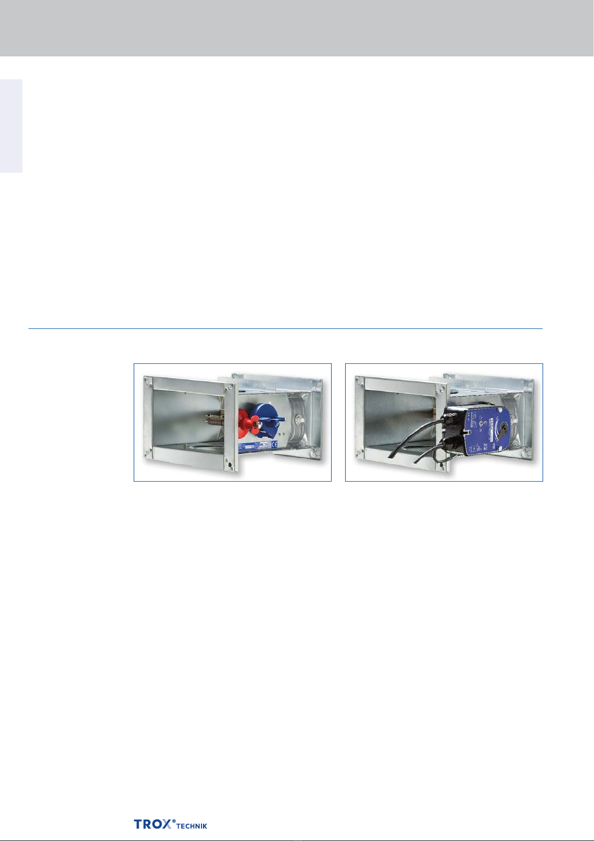
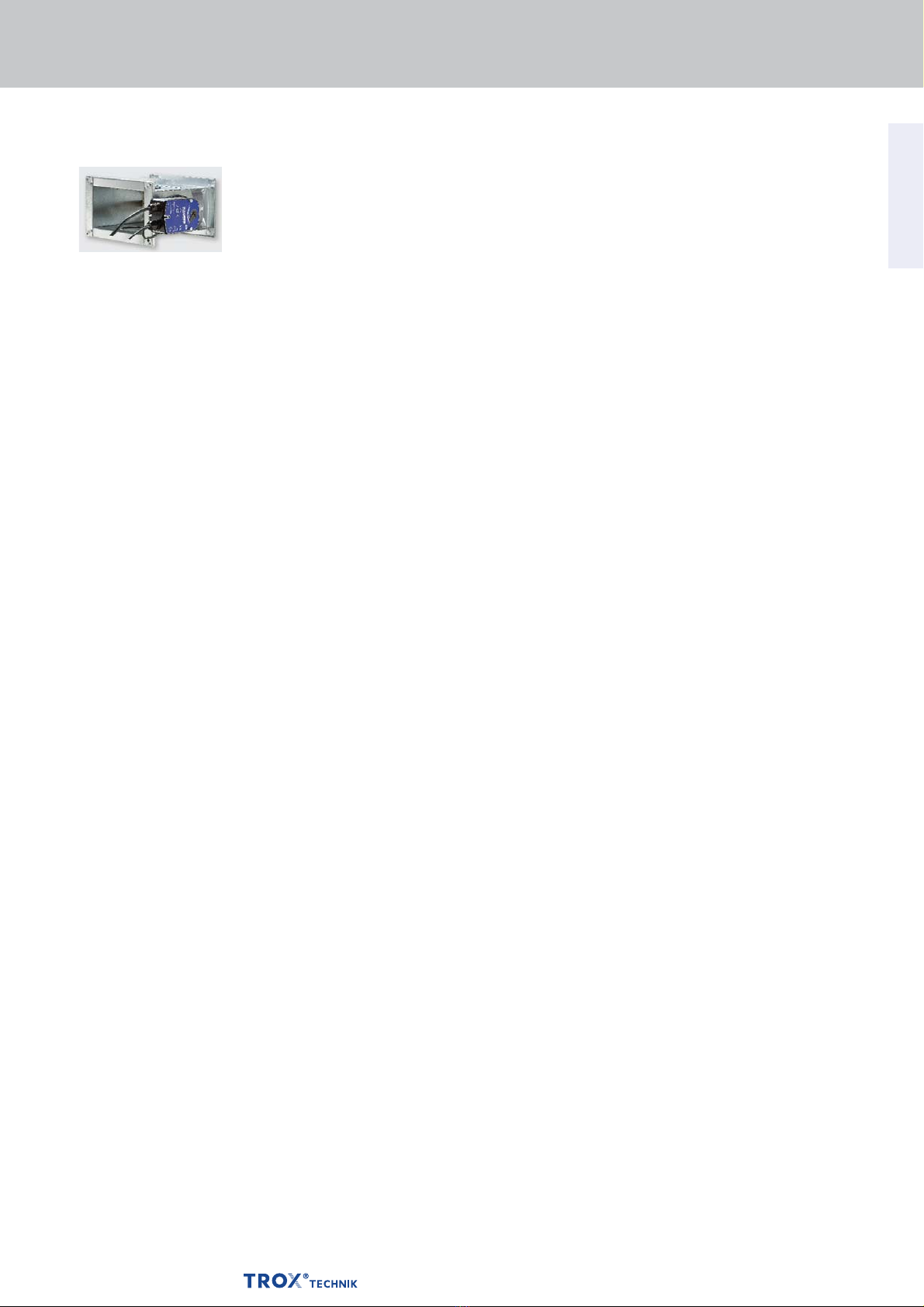
Variants
– With fusible link
– With spring return actuator
Nominal sizes
– B × H: 200 × 100 – 800 × 200 mm
(width in increments of 50 mm)
– L: 300 mm
Attachments
– Limit switch for damper blade
position indication
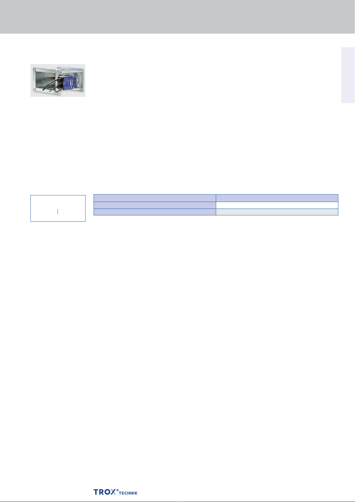
– Spring return actuator for 24 V AC/DC
or 230 V AC supply voltage
– Network module for the integration
with AS-i or LON networks
Accessories
– Cover plate (to keep the fire damper stable
and hence facilitate mortaring)
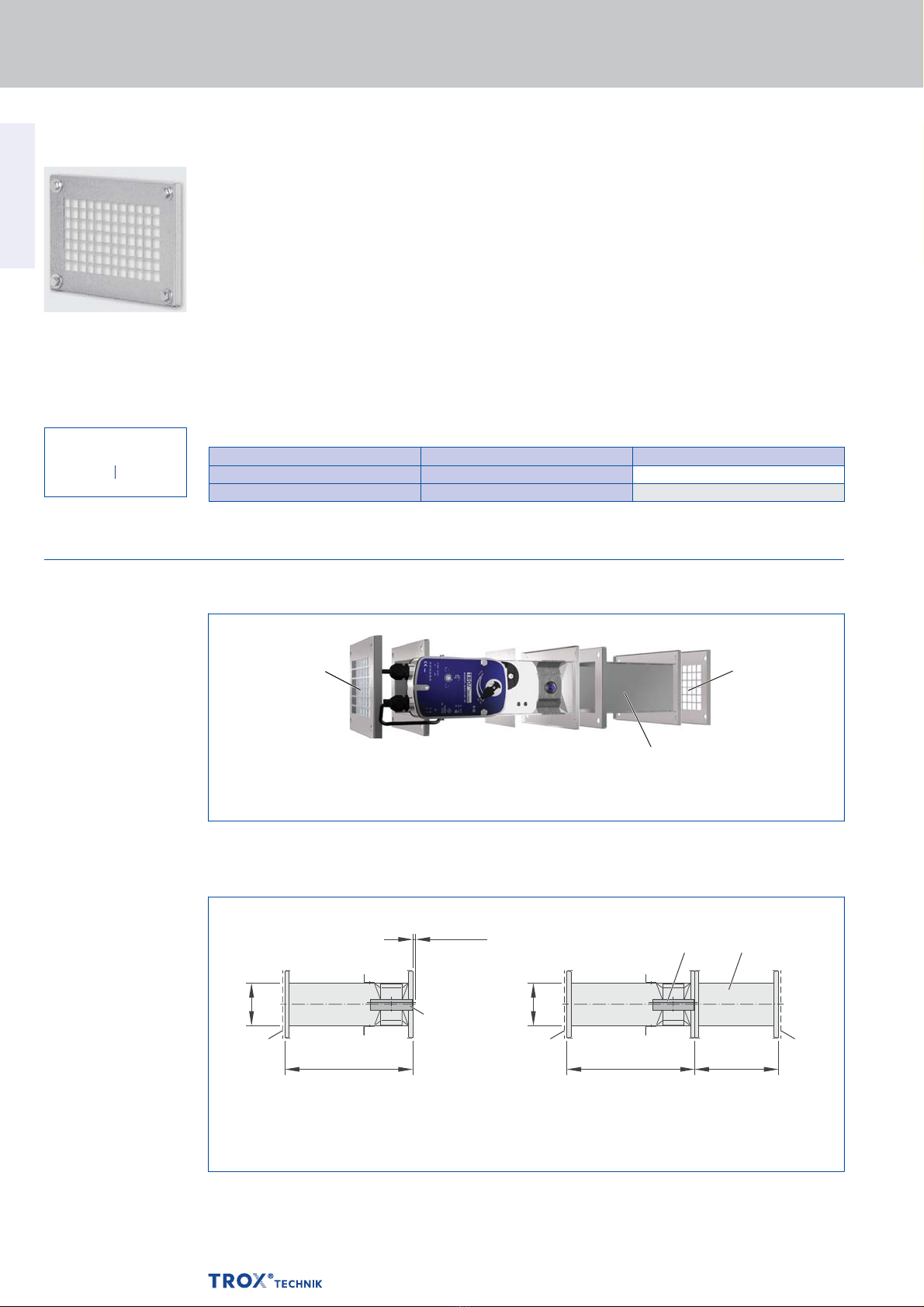
– Cover grille
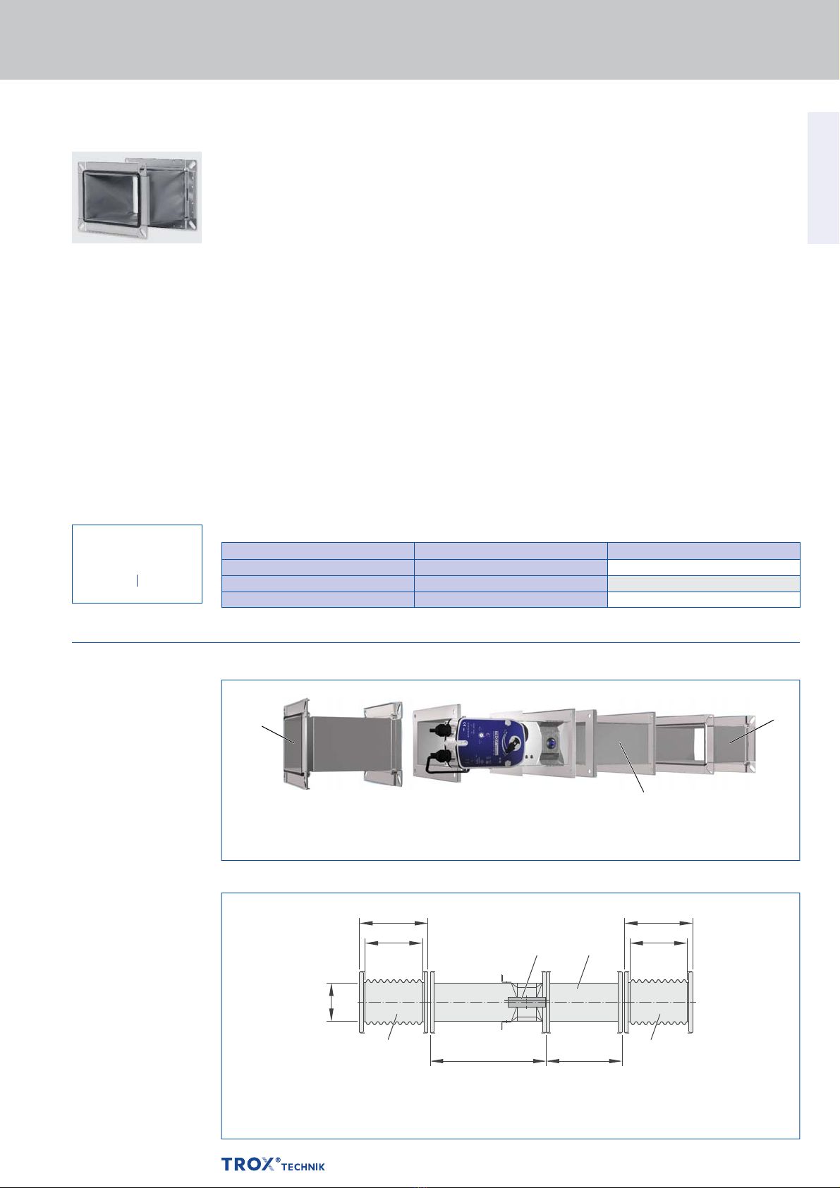
– Flexible
connectors
– Extension piece
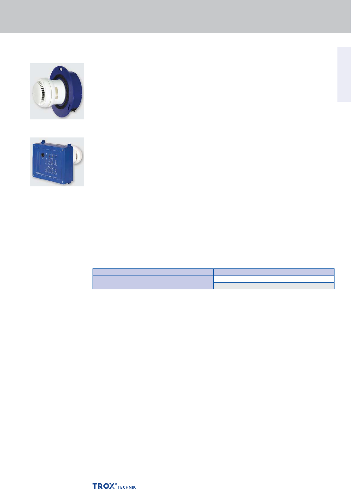
Useful additions
– Duct smoke detector RM-O-3-D
– Duct smoke detector
with airflow monitor RM-O-VS-D
Special characteristics
– Declaration of performance according
to Construction Products Regulation
– Classification to EN 13501-3,
up to EI 120 (ve, ho, i ↔o) S
– Building inspectorate licence Z-56.4212-991,
non-combustible and non-hazardous to health
– Complies with the requirements of EN 15650
– Tested to EN 1366-2
for fire resistance properties
– Hygiene complies with VDI 6022 part 1
(07/2011), VDI 3803 (10/2002), DIN 1946
part 4 (12/2008), and EN 13779 (09/2007)
– Corrosion protection according to EN 15650
in connection with EN 60068-2-52
– Closed blade air leakage to EN 1751, class 2
– Casing air leakage to EN 1751, class C
– Low differential pressure
and sound power level
– Any airflow direction
– Integration into the central BMS
with TROXNETCOM
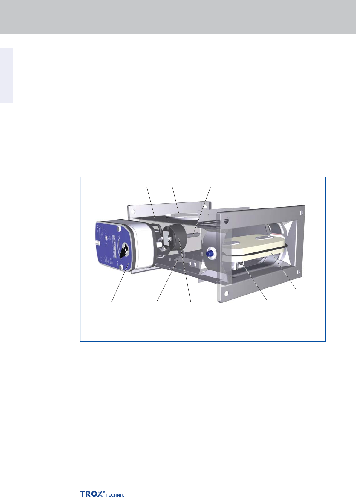
Parts and characteristics
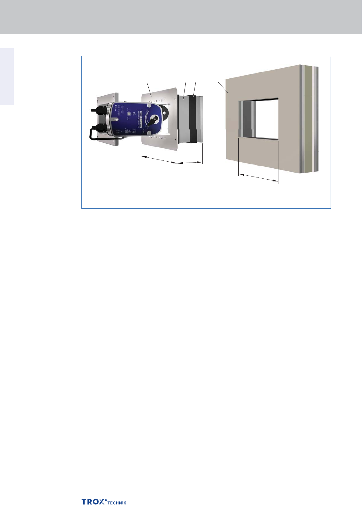
– Easy dry mortarless installation into solid walls
and ceiling slabs, lightweight partition walls,
fire walls and shaft walls using
an installation block
– Release temperature 72 °C or 95 °C
(for use in warm air ventilation systems)
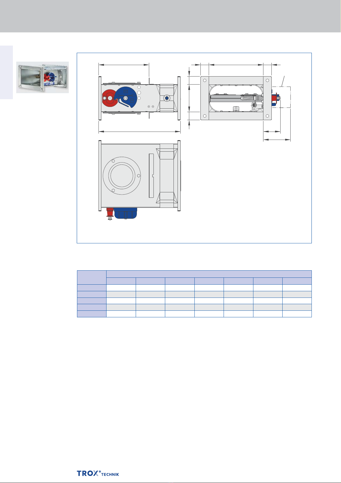
Construction features
– Rectangular or square construction,
rigid casing, both flanges with fixing holes
(System 30)
– Suitable for the connection of ducts,
flexible connectors or a cover grille
– The release mechanism is accessible
and can be tested from the outside
– Two inspection access panels
– Intermediate dimensions in 50 mm
increments for width
– Remote control with spring return actuator
Materials and surfaces
Casing:
– Galvanised sheet steel
– Galvanised sheet steel,
powder-coated RAL 7001
– Stainless steel 1.4301
Damper blade:
– Special insulation material
– Special insulation material with coating
Other components:
– Damper blade shaft made of galvanised steel
or stainless steel
– Plastic bearings
– Seals of elastomer
The construction variants with stainless steel
or powder-coated casing meet even more critical
requirements for corrosion protection.
Detailed listing on request.
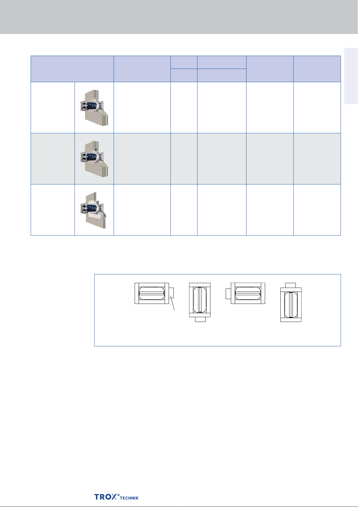
Installation and commissioning
Installion is to be carried out according
to the operating and installation manual
Mortar-based installation:
– In solid walls and ceiling slabs
– In lightweight partition walls and fire walls
with metal support structure
and cladding on both sides
– In shaft walls with metal support structure
and cladding on one side
Dry mortarless installation:
– In solid walls and ceiling slabs
with installation block E
– In lightweight partition walls with metal support
structure and cladding on both sides:
with
installation block E
– In shaft walls with metal support structure
and cladding on one side with installation
block E
K4 – 1.1 – 51
Description
Fire damper Type FKS-EU
For detailed information
on attachments
see Chapter K4 – 1.2.
06/2015 – DE/en