SMAY WKP-O User manual

a
Installation manual
WKP-O
Fire damper -
rectangular
v
https: //
www.smay.eu

Version 6.00
Date of editing: 16.09.2022 r.
Page 1 z 11
Installation manual
WKP-O
Version 6.00
SMAY reserves the right to make changes to this document.
TABLE OF CONTENT
INSTALLATION TECHNOLOGY.......................................................................................... 2
I. INSTALLATION TECHNOLOGY –RIGID WALL......................................................... 3
II. INASTALLATION TECHNOLOGY - PROMADUCT CHANNEL ........................................ 6
III. INSTALLATION TECHNOLOGY –STRUCTURES THICKER THAN 125 MM ..................... 7
IV. INSTALLATION TECHNOLOGY –LIGHT WALL......................................................... 8
V. INSTALLATION TECHNOLOGY –MKW HONEYCOMB MESH COVER .......................... 11

Version 6.00
Date of editing: 16.09.2022 r.
Page 2 z 11
Installation manual
WKP-O
INSTALLATION TECHNOLOGY
Before installing the fire dampers, make sure that there are no damage, during transport or storage, that could block
the baffle.
Check that the baffle can be opened and closed (full opening and closing position). To open fire dampers WKP-O use
the actuator key.
The opening and closing must proceed smoothly (not stepwise).
Do not pull by baffle to open or close fire damper, it may cause permanent damage, not covered by the warranty.
Before installation verify dimensions of the gap between bottom blade and inside part of the housing under the blade,
and between top blade and inside part of housing above blade. The dimension of the gap cannot be lower than 4 mm.
Before installing, secure the fire damper, by dust and dirt, using a foil or other screening material. It can prevent
components of fire damper by damage.
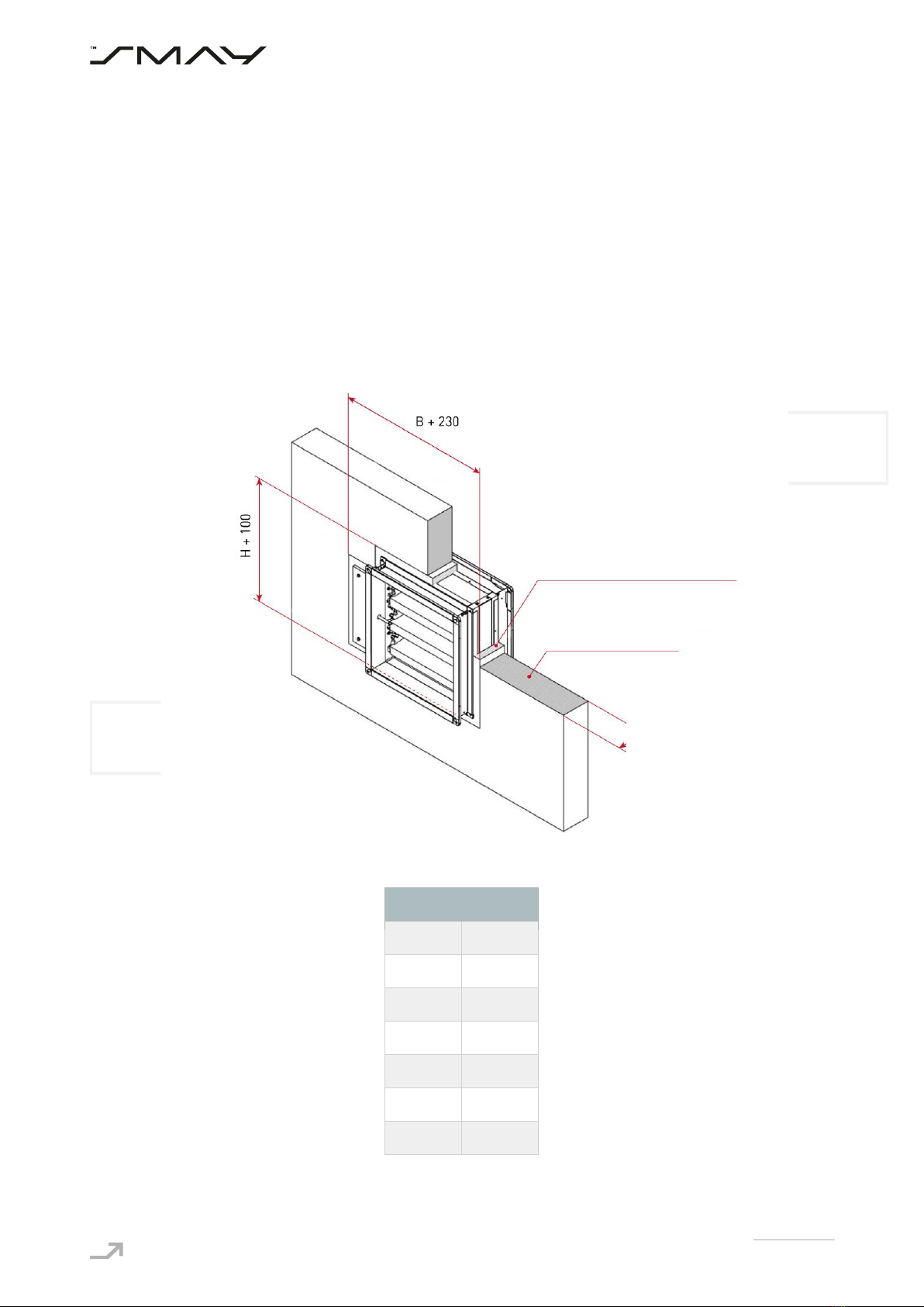
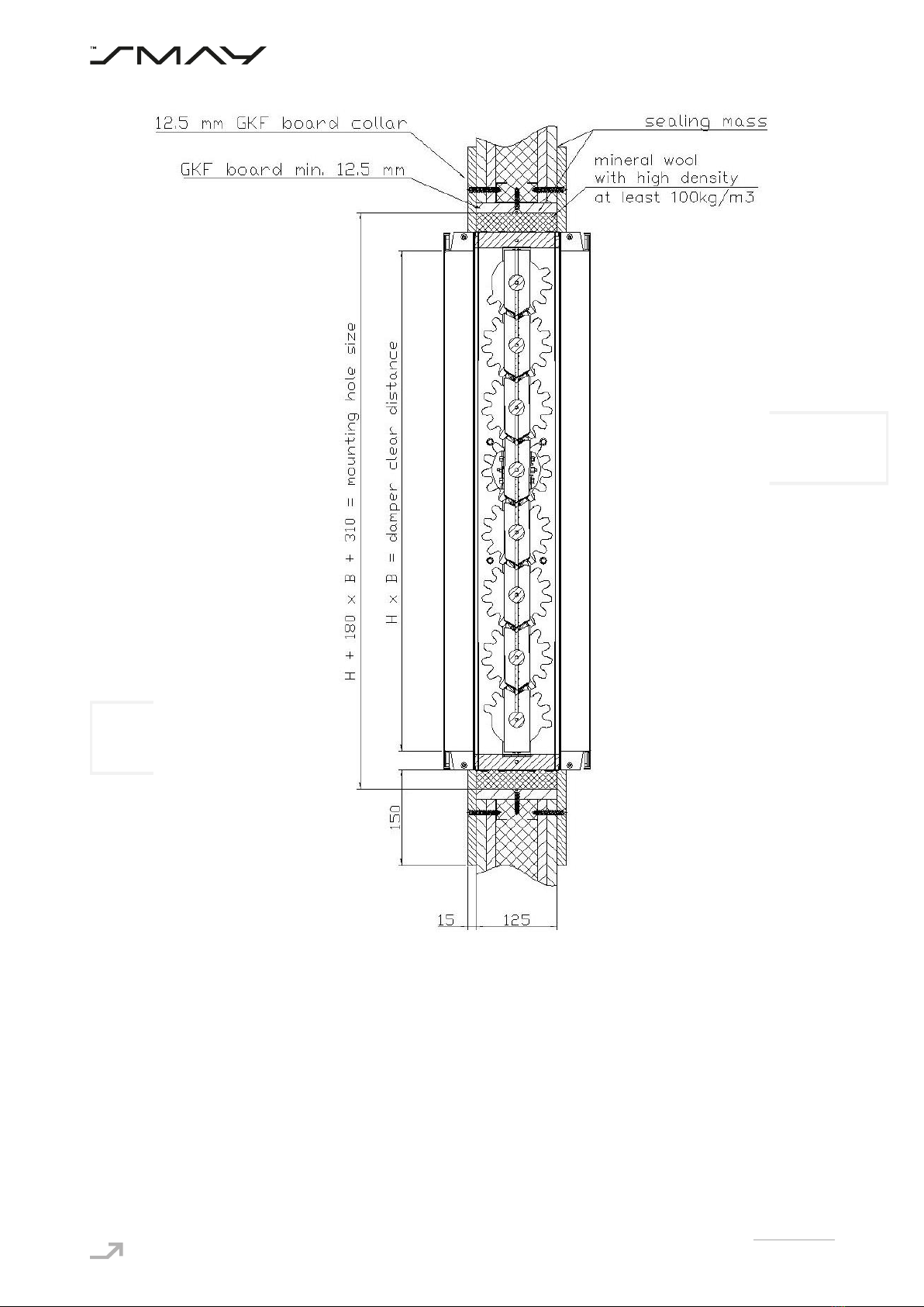
Dampers to preserve of the declared resistance, insulation and smoke leakage EIS120, EIS90, should be installed on
wall, which was classified as EIS120, EIS90.
It is allowed to install WKP-O dampers in wall with other fire-resistance, should be remembered that fire-resistance in
this situation is resistance of lowest classified (in this regard) element in this system.
Ducts made of flammable and non-flammable materials can be connected to the damper. Ducts should be installed
that they cannot load the damper during fire. Ducts lengthening during fire can be compensated by support and knee.
ATTENTION: Distance between fire dampers or fire damper and construction elements must be compatible with
standard 1366-2:
a. Minimal 200 mm between fire damper, which are installed in different ventilating wires,
b. Minimal 75 mm between fire damper and construction element (wall/ceiling).

Version 6.00
Date of editing: 16.09.2022 r.
Page 3 z 11
Installation manual
WKP-O
I. INSTALLATION TECHNOLOGY –RIGID WALL
a. Make an opening in the wall 230 [mm] (acceptable 210 ÷ 250 [mm]) greater than the dimension B and 100 [mm]
(acceptable 80 ÷ 120 [mm]) greater than the dimension H, that is B+230 and H+100.
b. For the dampers which have height H=200 mm and H=300 mm installation opening should have height H+160
[mm] (acceptable 140÷180 [mm]).
c. Put the closed fire damper into the installation opening and support or suspend, in this way that the axis of the fire
damper baffle matches the axis of the wall, and ensure a concentricity of fire damper and installation opening. The
damper should be protected against possible undesirable stresses, which could lead to deflection of the housing,
e.g. by using assembly struts.
d. After setting the fire damper as described, fill the gap between the fire damper and the wall with cement, cement-
lime mortar or concrete.
e. After drying of the mortar (approx. 48 hours), remove used supports or suspensions, check the fire damper
correct operation and leave it in fully open position.
In order to avoid filling the holes above and below the actuator housing, the opening for the WKP damper can be made
as shown in the figure below.
Figure 1. Dimensions of the installation opening of the WKP-O dampers in rigid wall with a horizontal and with vertical
axis of rotation of the baffle, with planned cut for actuator housing. The C dimension is given in the table.
N
C
2
0
3
100
4
100
5
200
6
200
7
300
8
300
N –number of blades in damper
Mortar, cement mortar,
cement-lime mortar or concrete
Rigid wall

Version 6.00
Date of editing: 16.09.2022 r.
Page 4 z 11
Installation manual
WKP-O
Figure 2. Installing method of WKP-O fire dampers in rigid wall.
Figure 3. Installing method of WKP-O fire dampers in rigid wall

Version 6.00
Date of editing: 16.09.2022 r.
Page 5 z 11
Installation manual
WKP-O
Figure 4. Installing method of WKP-O fire dampers in rigid wall with KST grille in rigid wall structure.

Version 6.00
Date of editing: 16.09.2022 r.
Page 6 z 11
Installation manual
WKP-O
II. INSTALLATION TECHNOLOGY - PROMADUCT CHANNEL
After setting the fire damper as described, and build it in wall, duct made of PROMATECT-L500 boards with 50 mm
thickness must be installed. The band around the duct must be made by PROMATECT-L500, with 50 mm thickness and
60 mm width. Connection of damper and the wall, and damper with the band must be made by K84 glue. The sides of
the duct and the band must be connected by using 4,2x90 –4,8x120 screws.
Figure 5. Installing method of WKP-O fire dampers with PROMAT boards duct.

Version 6.00
Date of editing: 16.09.2022 r.
Page 7 z 11
Installation manual
WKP-O
III. INSTALLATION TECHNOLOGY –STRUCTURES THICKER THAN 125 mm
In rigid walls, with thickness less than or equal to 125 mm, WKP-O fire dampers are installed in this way that an axis
of the fire baffle matches the axis of the wall, and ensure a concentricity of fire damper and installation opening.
In case when wall have more than 125 mm thickness: WKP-O fire dampers are installed in this way that the damper
border is flush with the wall surface (Fig. 6).
Figure 6. Installation method of fire dampers WKP-O in structures thicker than 125 mm

Version 6.00
Date of editing: 16.09.2022 r.
Page 8 z 11
Installation manual
WKP-O
IV. INSTALLATION TECHNOLOGY –LIGHT WALL
a. Make an opening in the wall with the dimensions 230 [mm] (acceptable 210 ÷ 250 [mm]) greater than the
dimension B and 100 [mm] (acceptable 80 ÷ 120 [mm]) greater than the heigh H, That is B+230 i H+100.
b. For the dampers which have height H=200 mm and H=300 mm installation opening should have height H+160
[mm] (acceptable 140÷180 [mm]).
c. Make a frame of two layers of GKF boards 15 mm thick and the width relative to the width of opening, mounting
by screws remembering to carefully seal the contact edges with a mastic: Hilti Firestop Coating CP 673,
Promastop-Coating, Promaseal-Mastic or Soudal Firesilicone B1 FR.
d. Put the closed fire damper into the installation opening and support or suspend, in this way that an axis of the
fire baffle matches the axis of the wall, and ensure a concentricity of fire damper and installation opening.
e. After setting the fire damper as described, fill the gap between the fire damper and the wall with non-flammable
mineral wool of high density, 100 kg/m3 or more.
f. Seal the place of filling with mineral wool using the sealing compounds given in pts.2
g. Mount collar, both side of wall, made of GKF boards, 15 mm thick and 150 mm wide, using screws,
h. After mounting the collar, remove the supports or suspensions, check the fire damper correct operation and
leave it in open position.

Version 6.00
Date of editing: 16.09.2022 r.
Page 9 z 11
Installation manual
WKP-O
Figure 7. Installation method of fire dampers WKP-O in standard wall with 125 mm thick

Version 6.00
Date of editing: 16.09.2022 r.
Page 10 z 11
Installation manual
WKP-O
Figure 8. Installation method of fire dampers WKP-O in standard wall

Version 6.00
Date of editing: 16.09.2022 r.
Page 11 z 11
Installation manual
WKP-O
V. INSTALLATION TECHNOLOGY –MKW HONEYCOMB MESH COVER
a. Before installing honeycomb mesh cover, glue self-adhesive ceramic gasket 5x10 on inner surface of mesh
cover along the bend edge around all perimeter.
b. Honeycomb mesh cover install to the wall with use metal pins for gas-concrete 6x32 and with use 5x40 screws.
c. Honeycomb mesh cover install in this way as shown in the figure below. Outer edges of openings on left side of
mesh cover and on a top and on a bottom must be in line with inner edges of the damper.
Figure 9. Installation method of MKW-B honeycomb mesh cover
Figure 10. Installation method of MKW-D honeycomb mesh cover
Other manuals for WKP-O
1
Table of contents
Other SMAY Fire And Smoke Damper manuals
Popular Fire And Smoke Damper manuals by other brands

Priorit
Priorit PRIODOOR ETX-RDA Assembly and operating manual

Nailor
Nailor 1210 Series OPERATIONS AND MAINTENANCE PROCEDURES

System air
System air OCWATERLOO PKIR3G ORIGINAL INSTALLATION, OPERATION AND INSPECTION MANUAL

Trox
Trox EK-JZ Installation and operating manual

TAKACHIHO
TAKACHIHO FYN-M 1 Series manual

Greenheck
Greenheck FSD Series Installation, operation and maintenance manual