Maico WRG 400 EC Service manual

WRG 300 EC
WRG 400 EC
Mounting and Operating Instructions
www.maico-ventilatoren.com

1
Table of contents
1. Introduction ........................................................................... 3
1.1 Product description .................................................................3
1.2 Scope of delivery.....................................................................3
1.3 Symbols in this manual ...........................................................3
2. Essential safety instructions ............................................... 4
2.1 General safety instructions .....................................................4
2.2 Intended use ...........................................................................4
2.3 Predictable misuses ................................................................4
2.4 Regulations for operation with fireplaces................................5
3. Construction.......................................................................... 6
3.1 Exploded view .........................................................................6
3.2 Unit components .....................................................................6
4. Operation ............................................................................... 7
4.1 General....................................................................................7
4.2 LED display system and operating panel ..............................7
4.3 Anti-frost protection .................................................................8
4.4 Filter status display .................................................................8
5. Installation ............................................................................. 8
5.1 General....................................................................................8
5.2 Wall assembly .........................................................................9
5.3 Connecting the channels.........................................................9
5.4 Connecting the condensation run-off ....................................11
5.5 Sound insulation....................................................................11
5.6 Electrical connection .............................................................12
5.7 Connections and dimensions of the WRG 300 EC...............14
5.8 Connections and dimensions of the WRG 400 EC...............15
6. Start-up................................................................................. 16
6.1 Switching ventilation unit on and off......................................16
6.2 Setting air volumes................................................................16
6.3 Settings made by the installer...............................................18
6.4 Menu structure display..........................................................19
6.5 Read-off value settings .........................................................21
6.6 Changing settings .................................................................22
7. Fault......................................................................................26
7.1 Fault analysis ........................................................................26
7.2 Filter status display ...............................................................26
7.3 Display of the codes..............................................................27

2
8. Maintenance.........................................................................28
8.1 Maintenance by the user.......................................................28
8.2 Maintenance by the installer .................................................29
9. Wiring plans / Diagrams .....................................................32
9.1 Simplified diagram without bypass........................................32
9.2 WRG 300 / 400 EC wiring diagram .......................................33
9.3 WRG 300 / 400 EC + RLS 2 F +
WRH in the supply air channel..............................................34
9.4 Air power diagram .................................................................36
10. Technical data .....................................................................37
11. Service..................................................................................38
11.1 Exploded view of the WRG 300 / 400 EC ............................38
11.2 WRG 300 / 400 EC spare parts ............................................38
11.3 WRG 300 / 400 EC accessories ...........................................39
12. Disposal................................................................................39
12.1 Packaging..............................................................................39
12.2 Air filter ..................................................................................39
12.3 Old units ................................................................................39

3
i
1. Introduction
1.1 Product description
This product from the advanced Maico WRG
300 / 400 EC model range is a heat recovery
unit with an efficiency rate of 90 % and en-
ergy-saving fans for a constant volumetric
flow. The new generation is characterised by:
●air flow rates that can be adjusted continu-
ously through the operating panel
●a filter status display on the unit
●a new frost-protection system for optimum
unit performance, even at very low external
temperatures
●low noise levels
When delivered, the unit is ready for service.
All operating elements are installed and
tested before leaving the factory. During
installation, the unit has to be connected to
the air channels, the condensation connec-
tion, the mains power and a controller.
The installer can modify the required air flow
for each setting through the operating panel
at the unit. You will find an exact description
in Chapter 4.
The WRG 300 / 400 EC is designed for a
maximum ventilation power of 300 / 400 m3/h
at a resistance of 150 Pa in the channel
system. The minimum volumetric flow is 70
m3/h.
1.2 Scope of delivery
●Ventilation unit.
●These mounting, operation and mainte-
nance instructions.
1.3 Symbols in this manual
WARNING symbol:
Here, extreme care and caution are
called for. In the case of malprac-
tice, there is a direct risk of injury to
the system operator or to a third
party. Non-observance can cause
damage to the ventilation system.
INFO symbol:
Text passages marked with this
symbol contain important informa-
tion and tips.
●Symbol for lists:
Here, you will find important infor-
mation about the subject.
¾Symbol for requests for action:
Here, you are asked to take ac-
tion. Follow the instructions
given, in the order stated.
A
cknowledgements:
© MAICO Elektroapparate-Fabrik GmbH.
Translation of the original manual. We are not
responsible for mistakes or printing errors and
retain the right to make technical modifications
without giving prior notice.

4
i
i
2. Essential safety instructions
2.1 General safety instructions
●Electrical installation and repairs are only
permitted when carried out by trained
specialists.
●Ask your installer to instruct you in the
ventilation unit and operating unit.
●Switch the ventilation unit off immediately
if you discover damage or faults that could
endanger persons or property. Prevent
further use.
●Disconnect the ventilation unit from the
mains before any cleaning or maintenance
work.(Switch off mains fuse in fuse box
and position a clearly visible warning notice
to avoid the unit being accidentally
switched back on.)
●Do not modify the unit in any way.Only use
original spare parts.Danger of injury.
MAICO does not assume any liability for
modified units or parts from other manufac-
turers.
●Never operate the ventilation unit without
all duct connections and sound absorbers.
Sound absorbers significantly reduce the
noise emissions.
●Never operate the ventilation unit without a
filter.
●Check the filter regularly for dirt and dam-
age. See "Maintenance” chapter.
●After the unit has been switched off for
some while, e.g. in the summer, replace
the filters before starting up again to en-
sure complete hygiene.
The unit is not intended to be used by
people whose physical, sensory or
mental capabilities are not sufficient
for them to understand and put into
practice the safety information pro-
vided in these instructions. This limita-
tion also applies to children.
The unit may however be safely used
by such persons if they are super-
vised by someone responsible for
their safety or if they are instructed in
a suitable way.
2.2 Intended use
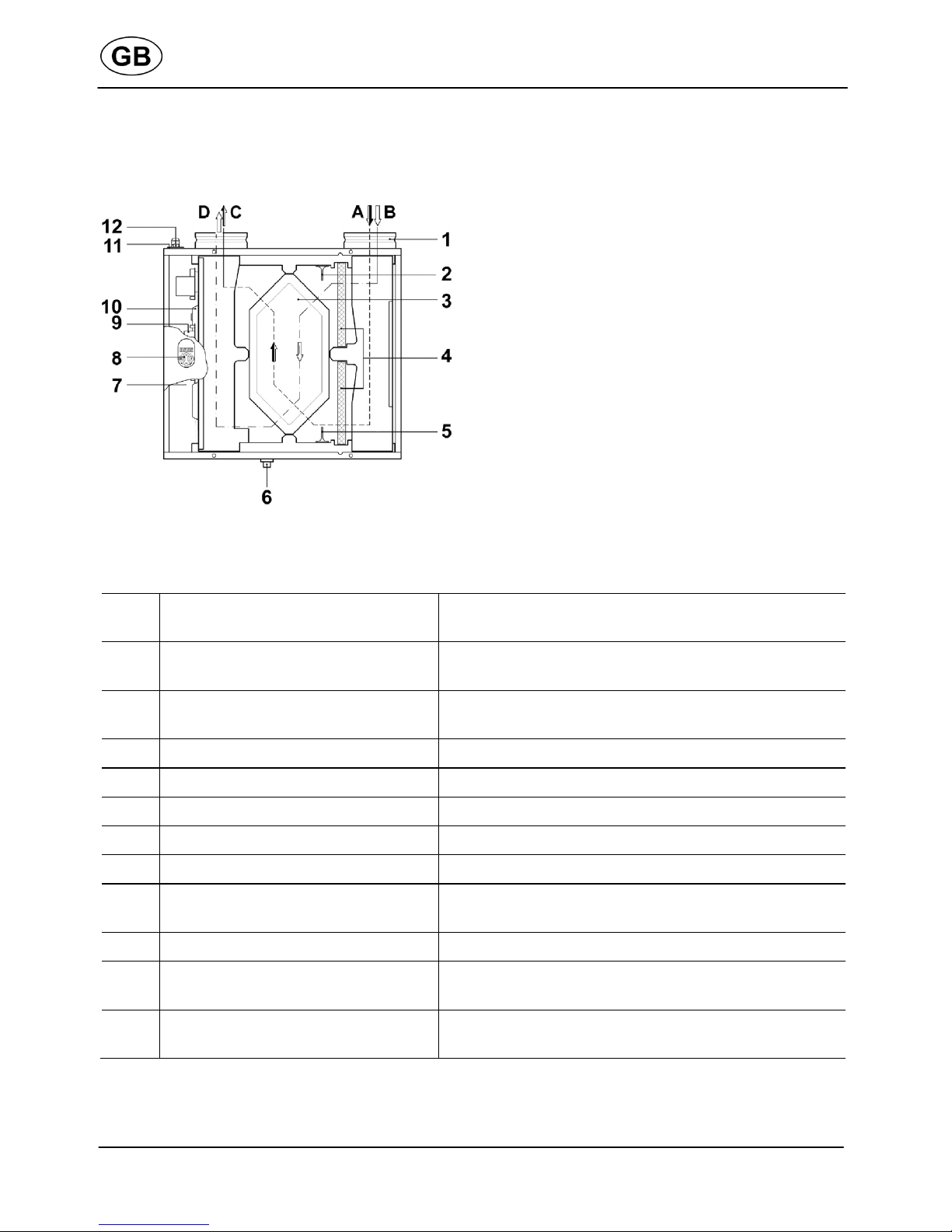
●The WRG 300 / 400 EC unit is a central
ventilation unit with heat recovery for vent-
ing and extracting air in one or more
rooms.
●The unit usually extracts the exhaust air
from kitchens, bathrooms and WCs with
high odour and humidity levels and feeds
fresh air to the bedrooms and living rooms.
●For the controlled ventilation of apartments
and single family-unit houses.
●The ventilation unit may only be used in
line with the calculations carried out by the
Engineering office.
2.3 Predictable misuses
Maico is not liable for damages caused by
usage not for the intended purpose.
The fan unit should not be used:
●close to flammable materials, liquids or
gases.
●to convey chemicals,
aggressive gases or vapours.
●in potentially explosive atmospheres
●in swimming pools
●for drying out new builds
●in combination with laboratory extractors.
●in combination with extractor hoods that
are connected directly to the controlled
domestic ventilation exhaust air channel.
For energy-usage reasons, we rec-
ommend using extractor hoods in
circulating air mode.
This manual suits for next models
1
Table of contents
Other Maico Test Equipment manuals
Popular Test Equipment manuals by other brands

Redtech
Redtech TRAILERteck T05 user manual

Venmar
Venmar AVS Constructo 1.0 HRV user guide

Test Instrument Solutions
Test Instrument Solutions SafetyPAT operating manual

Hanna Instruments
Hanna Instruments HI 38078 instruction manual

Kistler
Kistler 5495C Series instruction manual

Waygate Technologies
Waygate Technologies DM5E Basic quick start guide

StoneL
StoneL DeviceNet CK464002A manual

Seica
Seica RAPID 220 Site preparation guide

Kingfisher
Kingfisher KI7400 Series Training manual

Kurth Electronic
Kurth Electronic CCTS-03 operating manual

SMART
SMART KANAAD SBT XTREME 3G Series user manual

Agilent Technologies
Agilent Technologies BERT Serial Getting started