Make Mendel MegaBot User manual

MAKE MENDEL
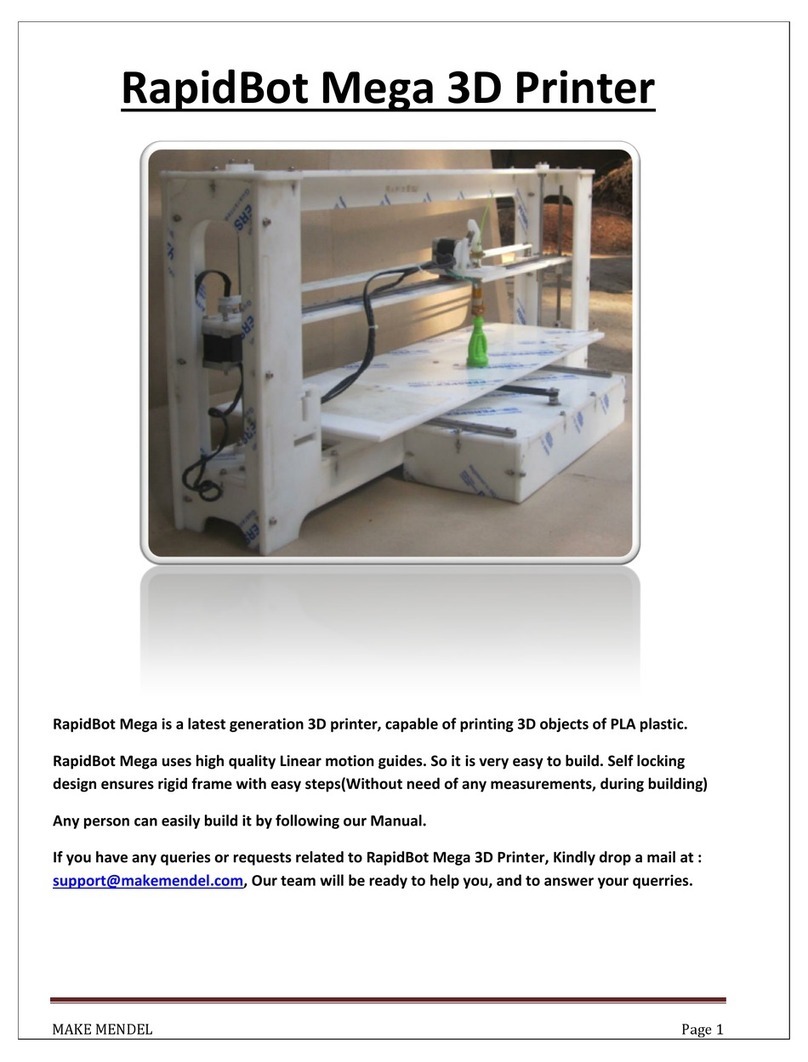
MegaBot
MegaBot
is a latest generation 3D printer, capable of printing 3D objects
MegaBot
uses high quality Linear motion guides. So it is very easy to build. Self locking design
ensures rigid frame with easy steps(Without need of any measurements, during building)
Any person can easily build it by following our Manual.
If you have any queries or requests related to
support@makemendel.com
, Our team will be ready to help you, and
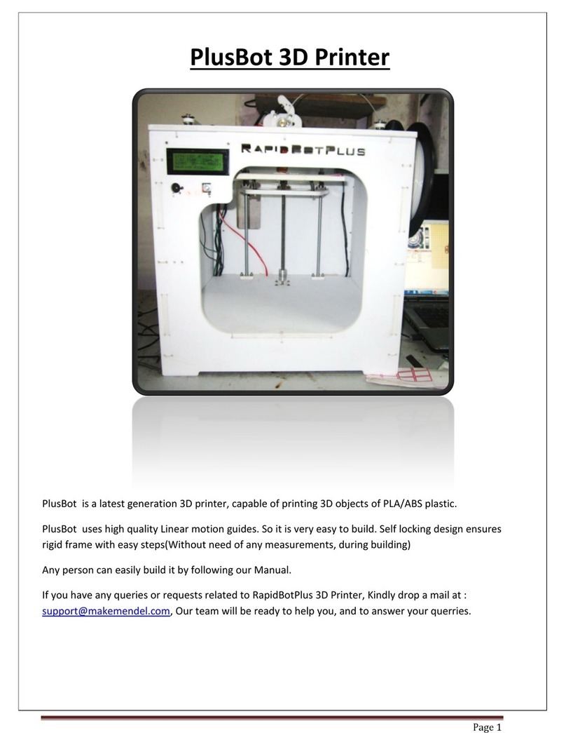
MegaBot
3D Printer
is a latest generation 3D printer, capable of printing 3D objects
of PLA
plastic.
uses high quality Linear motion guides. So it is very easy to build. Self locking design
ensures rigid frame with easy steps(Without need of any measurements, during building)
Any person can easily build it by following our Manual.
If you have any queries or requests related to
MegaBot
3D Printer, Kindly drop a mail at :
, Our team will be ready to help you, and
to
answer your querries.
Page 1
plastic.
uses high quality Linear motion guides. So it is very easy to build. Self locking design
ensures rigid frame with easy steps(Without need of any measurements, during building)
3D Printer, Kindly drop a mail at :
answer your querries.

MAKE MENDEL Page 2
Technical Specification :
• Machine size 400 x 1000 x 400 mm
• Build size 220 x 740 x 165 mm
• Nozzle Diameter : 0.4mm
• Layer Thickness : 0.1mm
• Speed : 60 mm/s
• Positioning Precision : 27 microns
• Input Format : STL
• Software : Pronterface (Available on site for free under Download section)
•System Compatibility : Windows 7 and Vista
• Power Supply : ATX, 450W
• Weight (Kg) : 32
Features :
1) It uses high quality linear motion guides.
2) LCD Controller Support
3) Acme Lead screw with nut
4) Spring Printrbed Adjustment, which keep Printbed more stable.
5) Printrboard and Power Supply are adjusted at the bottom to give clean and neat look.
6) Very easy to build, just 8-10 hours.
7) High quality aluminium pulley with T2.5 belts for Accurate and easy belt placement.
8) Large build volume with easy accesibility.
9) Uses high quality acrylic from http://www.perspex.co.uk
10) Self locking design ensures rigid frame with easy steps(Without need of any
measurements, during building).

MAKE MENDEL Page 3
Assembly of MegaBot

MAKE MENDEL Page 4
Part List For MegaBot-Acrylic Sheets
Qty Part Drawing
1 RightPlate
1 LeftPlate
1 XPlate
1 FrontPlate
1 BackPlate
1 TopPlate
1 BottomPlate

MAKE MENDEL Page 5
1 PrintBed-SupportPlate
1 GlassPrint Bed
1 AcrylicPrintBed
3 PCB HeatBed
1 ExtruderBasePlate
1 ExtruderMotorPlate
1 Driven Holder
1 Idler Holder
2 X-Rail Top Plate
4 TopSmoothRodCap(2with Counter sinkfor
Front Side)
4 BottomSmoothRodCap
1 Acrylic Support for ZMechanical switch
8 GlassSupportSquareBlocks
12 BearingSupport in XPlate
1 T2.5 Belt
1 MK7 Drive Gear

MAKE MENDEL Page 6
Hardware
Qty Part Drawing
57(36inBag+
21Attached) M3 Nylock Nut
(16BigRail+ 8SmallRail, 16Flange
Bearing+8FlangeNut+1Extruder Idler+8
Glass support)
28 M4 Nylock Nut
(4 Belt idler+ 2 Belt Idler +
16SmoothRodCap+
2MotorMountingPlate+ 4PrintBed)
6 M2.5x20 Screw
(4Mechanical Switch + 2LCD)
3 M2.5x25 Screw
(2Mechanical Switch + 1LCD)
9 M2.5 Sada Nut,
(6Mechanical Switch + 3LCD)
17 M3x12 SocketCapScrew
(Motor Mounting)
23 M3x15 SocketCapScrew
(20Rail + 3Extruder mounting plate)
31 M3x20 SocketCapscrew
(16FlangeBearing + 8FlangeNut + 6Rails +
1-623 Bearing)
12 M3x25 CounterSink
(4Extruder Base Plate+8GlassSupport)
2 M4 x20 SocketCapscrew
(MotorMountingPlate)
12 M4x25 SocketCapScrew
(SmoothRodCap)
4 M4x25 CountersinkScrew
(SmoothRodCap)
4 M4x50 CounterSink
(4PrintBed)
3 M4x40 SocketCapScrew
(2Belt Idleon TopPlate + 1ZSwitch)
4 M4x60 SocketCap
(Belt Idler)

MAKE MENDEL Page 7
5 SMPS mountingScrew
103 M3 Washer
54 M4 Washer
14 M4x10 Washer
(12Belt Idler + 2Z Mechanical switch)
22 624-Bearing
(Belt Idler)
2 623-Bearing
(Extruder)
2 Flange nut
4 Flange bearing
2 Coupling 5 _8
2 Soft Spring
(1Extruder + 1ZSwitch)
4 Hard spring
(PrintBed)
3 Dummy Rails
1 Forceps
1 FeviQuick
35 Small Plastic Tie
35 Big Plastic Tie
1 Small Linear Motion Guide
(XAxis)
2 Large Linear MotionGuide
(2YAxis)

MAKE MENDEL Page 8
Hotend and Electronics
Quantity Part Drawing
5 Stepper Motors-NEMA 17
3 StepperMotor ExtensionCable
2 T2.5 Timing Pulley_5mmBore (For
X-Y Motor)
1 J HotEnd withCartridge heater
2 J-Hotend Extension Cable
1 Printrboard REV D Electronics
Board
1 Jumper for PrintrBoard
1 LCD
1 LCD flat cable
1 LCD connection PCB
1 Micro SD
3 Mechanical switchwith 3 pin
Molex Connector
1 Z Prusa cable
1 Thermistor G550 EPCOS
2 Teflon sleeve
3 2 pin TeflonMolex connector
1 Cooling Fan 60 x 60
1 USB Printer cable

MAKE MENDEL Page 9
1 Universal Travel Adaptor
1 SMPS
2 Kapton Tapes (50mm + 15mm)
1 Magnetic Leveler
1 10m samplePLA
2 M8 ThreadedRod -285mm
1 Spool Holder-125mm
4 Smooth Rod(8mm Dia)-333mm
1 Paper Tape50mm wide
1 Allan Key 2
(M4-GrubScrew, Pulley+MK7)
1 Allan Key 2.5
(M3 Socket Cap Head)
1 Allan Key 3
(M4 Socket Cap Head)
1 Wrench 5mm, 7mm
(For M3 and M4)
NOTE:
Dummy Rails: Dummy rails are given for maintenance purpose, if you will need in future. Be
careful while removing the LM block from the Rail. Put dummy rail on block before removing it.
4 pin Molex Connector: We give one extra.
Cooling Fan: Cooling Fan are needed for ABS , If you are using PLA there is no need of Cooling fan
Hotend: We provide are pre-solder Hotend
End Stops: When you press Print button, basically all 3 axis move to its HOME position. HOME
position is detected by Mechanical Switch. When switch is pressed, then printer understands that,
it has reached its home.
So there are 3 mechanical switch, 1 for each axis(X,Y,Z).
So, there is a Z Flag, which should go into the Z Optical switch, If z switch is moved during
shipping, then adjust it, so that it is pressed when nozzle is around 0.2 mm distance from
PrintBed..

MAKE MENDEL Page 10
List of Frames
2x Side Plates: Front Plate:
Back Plate :
XPlate

MAKE MENDEL Page 11
Assemble Bottom Plate :
1) Attach the Circuit board (Printrboard) at the bottom of the bottom-Plate, using Plastic
Ties.
2) Attach two Z motors at the Bottom plate.
3) Use Z Prusa cable to connect two Z motors, whose one end will go to Printrboard.
Z Mechanical Switch Assembly
1) Using Acrylic part and Screws (M2.5 x 25) given place the mechanical switch at the Side plate.
2) Assemble M4 Nylock, M4x40 Screw, Soft Spring, Mudguard Washer and place above the
Mechanical switch to limit the switch.

MAKE MENDEL Page 12
FRAME ASSEMBLY
Fix Two side plates with Bottom Plate Using plastic ties.
Mechanical Switch
To Limit the
Mechanical Switch

MAKE MENDEL Page 13
Assembly of X Plate
1. Now we will assemble X Plate.
2. Put Rail along with block on X Plate. Rail is pre assembly by our team.
3. Put two acrylic blockson Rail Block.
4. On Top of that putthe extruder, which is pre assembled. Use Screws to fix the
extruder on Rail.

MAKE MENDEL Page 14
5. Now will assemble XMechanical switch on X plate. Use M2.5 x 25 Screw to fix it at
proper place. Mechanical switch is soldered to two pin Molex already which will go
to Printrboard (X-STOP).
6. Your X Plate is readywith complete Extruder placed on it.

MAKE MENDEL Page 15
Assembly of Printbed Support Plate
1. Assemble Flange bearing at both corners ofPrintbed Support Plate using M3x20 Cap
Screws.
2. Fix the flange nut ofLead screw using M3x20 Cap Screws.
3. Assemble the other side Support plate following step no.1 & 2.
4. Both Side PrintbedSupport plates areready with us.
Assembly of Rods
1. Facing machine fromfront, rod assemblyfor left side as follows.
2. Put the couplingat the bottom side of Lead screw (8mm side). Other side of
coupling will be fixed in motor shaft (5mm side). Motor is already fixed on Bottom
plate.

MAKE MENDEL Page 16
3. Place Lead screw (Threaded) at the center of Bottom plate. Place Smooth rods on
either side of lead screw. Fix the base of smooth rod in smooth rod caps using
screws.
4. Repeat step no.2 &3 to do assembly of rods on right hand side.
5. Now your rods are fixed on Bottom plate.

MAKE MENDEL Page 17
Glass Printbed Assembly
1. Place glass on Printbed Support plate. Be very careful with glass. Take your friends
help while fixing glass to hold it from other side.
2. Using plasticZiplock ties fix the Glass fromall the 4 Corners.
3. Use the small 8 xacrylic Blocks given. They are to give support to glass printbed, so
that it will not shakeand will keep the glass in a fix place.
4. Use plastic tiesto fix those 8 x small acrylic blocks.

MAKE MENDEL Page 18

MAKE MENDEL Page 19
Before moving to Top plate assembly will keep the belt adjuster ready, so that belt placement
will be much handy.
Assemble a set of 624 Bearings, M4x40 Socket, Mudguard, M4 washer, and M4 Nylock nut.
Top Plate Assembly
1. Place the two motors at each corner of Top plate using M3 x 12 screws, fix T2.5
pulleys to the motor shaft.
2. On the Bottom sideof Top plate fix rails using screws at the end of each rail, use
screws at alternative holes on rail to keep to properly place.

MAKE MENDEL Page 20
3. Turn around your Top plate, Put alreadyassembled X plate on rail blocks. Use
screws to fix it. move Xplate forth and back, just to check the Rapid movement.
Table of contents
Other Make Mendel 3D Printer manuals
Popular 3D Printer manuals by other brands

Zcorporation
Zcorporation Z810 System user manual

3D Upfitters
3D Upfitters CR-10S Pro/CRX R1 Enclosure Kit instruction manual

3D Upfitters
3D Upfitters Prusa i3 Enclosure Kit installation manual

Flashforge
Flashforge Inventor user guide

Creality
Creality CR-10 S5 Complete Setup Guide

Anet
Anet ET5 X user manual