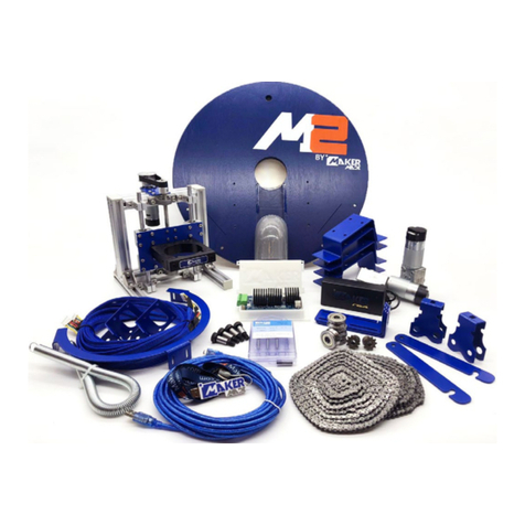
Makermade M2 User instructions

SETTING UP YOUR
M2 AUTOMATED CUTTING MACHINE KIT
The official assembly guide by
Last Updated 8.12.2020 v1.8

2
M2 ASSEMBLY GUIDE
SETTING UP YOUR M2
TABLE OF CONTENTS
SECTION 1. What’s in Your Kit?
SECTION 2. Building the Frame
SECTION 3. Assembling the M2
SECTION 4. Calibrating and Operating
SECTION 5. Tips and Safety Warnings
**Disclaimer: Due to the prototyping nature of CNC development during a global pandemic, some pictures may vary from
the M2 parts in your kit. Let us know how this guide can be improved for beginners. We love to hear from you!**
This work is licensed under the creative commons Attribution
NonCommercial-NoDerivatives 4.0 International license. Last Updated 8.12.2020
Version 1.8

3
M2 ASSEMBLY GUIDE
WHAT’S IN YOUR KIT
Item
DUE Case-bottom
DUE Case-top
v1.2 Control Board
v1.2 DUE Control Shield
Micro-USB connector- 10ft
AC/DC Power Adapter (3 meter lead cable) w/ Sticker
120/240 Volt Power Cable (to adapter)
X/Y Axis Motors (ETONM)
Motor Power Cables (JST XH 6Pin to XH 6Pin)
Motor Mounting Brackets
Z Axis Mount
Ring Carriage
Ring Carriage Bearings
Roller Chains (335cm / 11 feet)
Sled
Stud Mount
Suction Cover
PVC Elbow 2”
Z Axis Motor (ETONM)
Z-Axis Motor Power Cable (JST XH 6Pin to PH 6Pin)
Meticulous Z Assembly; pre-assembled
Lanyard 15mm full color die-sub
16GB USB Drive with Firmware/Software/Instructions
MM White Sticker
Info sheet on FB community
Paint marker
Spring
Router Bit Case
1/4” upcut bit
1/8” downcut bit
2in wide black rubber stripping
Quantity
1
1
1
1
1
1
1
2
2
2
3
2
4
2
1
4
1
1
1
1
1
1
1
1
1
1
1
1
1
2
1
This work is licensed under the creative commons Attribution
NonCommercial-NoDerivatives 4.0 International license. Last Updated 8.12.2020
Version 1.8

4
M2 ASSEMBLY GUIDE : WHAT’S IN YOUR KIT
Item
Bag A
Cotter Pins to Secure chain to ring
Chain Guide
Chain Alignment Spacer
Chain Spacer Nail
Chain Nail
Bag B
Cable Tie
M5 Quick Link
Arduino Screws
Bag C
Brick Mounting Bolts
split washer
Nylon nut
Butterfly nut
Brick straps
Bag D
Short Wood Screws
#6-9 x 2-1/2” Phillips Bugle Head
Bag E
X/Y Axis Motor Mounting Screw
X/Y Axis Motor Split Lock Mounting Washer
Set Screw for Motor Sprocket
Set Screw Allen Wrench (3mm)
Motor Sprocket for Chain
Bag F
Shoulder Bolt
Shoulder Bolt Nut
Shoulder Bolt Washer
Shoulder Bolt Allen (5mm)
Bag G
Ring To Brace Bolts
M3-0.5 Wing Nut
Ring Brace Screws
Ring To Brace Bolts Allen (2mm)
Quantity
2
2
2
2
2
12
2
4
4
4
2
2
2
34
8
8
8
2
1
2
4
4
8
1
12
12
24
1
This work is licensed under the creative commons Attribution
NonCommercial-NoDerivatives 4.0 International license. Last Updated 8.12.2020
Version 1.8

5
M2 ASSEMBLY GUIDE
BUILDING YOUR FRAME
This work is licensed under the creative commons Attribution
NonCommercial-NoDerivatives 4.0 International license. Last Updated 8.12.2020
Version 1.8

6
M2 ASSEMBLY GUIDE
The first step to starting your M2 CNC adventure is to build the frame that will hold your
material and the M2 while it cuts. The M2 mounts for your frame are included, but you will
need to purchase the following from a local hardware store:
Item
Standard Sized Bricks
2”x4”x8’
2”x4”x10’ Board
1”x6”x8’ Board
4’x8’x3/4” Plywood or MDF
Quantity
2
1
1
2
1
Top Beam: 2"X4"10'
2x Leg: 2"X4"X4'
Footer: 1"X6"X8'
Support: 1"X6"X8' Cut to 93"
Waste Board: 4'X8' Plywood
314.8 [12.4in]
32 [1.3in]
19.45 [.8in]
19.45 [.8in]
8X
1
8
"
Pilot Holes
Top Beam: 2"X4"10'
2x Leg: 2"X4"X4'
Footer: 1"X6"X8'
Support: 1"X6"X8' Cut to 93"
Waste Board: 4'X8' Plywood
314.8 [12.4in]
32 [1.3in]
19.45 [.8in]
19.45 [.8in]
8X
1
8
"
Pilot Holes
PURCHASE
LIST
Name
Bricks for sled weight
For Legs
Top Beam
Footer, Support Piece
Wasteboard
2”x4”x4’ Board
1”x6”x7’ 3/4” Board
2
1
Legs
Support Piece
CUT
LIST
We recommend reading this entire section before beginning.
Top Beam: 2"X4"10'
2x Leg: 2"X4"X4'
Footer: 1"X6"X8'
Support: 1"X6"X8' Cut to 93"
Waste Board: 4'X8' Plywood
314.8mm [12.4in]
32mm [1.3in]
19.45mm [.8in]
19.45mm [.8in]
8X
1
8
"
Pilot Holes
1. PURCHASE LIST
This work is licensed under the creative commons Attribution
NonCommercial-NoDerivatives 4.0 International license. Last Updated 8.12.2020
Version 1.8

7
M2 ASSEMBLY GUIDE
2. BUILDING THE FRAME
The Frame has 2 main parts: The Top Beam that holds the motors (we recommend attaching
it to a wall) and the Wasteboard on which you will clamp the material you want to the M2 to
cut.
The size of material the M2 can cut is only limited by the chain length. These instructions are
based on the chain included with your M2 and will walk you through how to set up your kit to
cut material as large as 4’x8’.
STEP 1
Measure wall studs for Stud Mounts that will hold the Top Beam
STEP 2
Attach Stud Mounts to Top Beam, at measured distance of wall studs. Then attach Top Beam
to wall, aligning Stud Mounts with Wall studs.
92 "
Step 1: Attach Stud Mounts to wall
65 3
4" up from floor
(a) Find stud and attach
first Stud Mount using 2pcs
long wood screws in Bag D
(b) Attach Stud Mount
using 2 drywall anchors
and 2pcs long wood
screws in Bag D
Step 2: Mount Top Beam to Stud Mounts on wall
ASSEMBLY GUIDE
Use 8pcs short wood screws in Bag D to attach top beam
Step 3: Attach last two Stud Mounts
146mm [5.75in]
146mm [5.75in]
Stud Mounts directly below
first Stud Mounts
This work is licensed under the creative commons Attribution
NonCommercial-NoDerivatives 4.0 International license. Last Updated 8.12.2020
Version 1.8

8
M2 ASSEMBLY GUIDE
STEP 3
Attach last 2 Stud Mounts to wall for Wasteboard
STEP 4
Attach Footer to Legs
92 "
Step 1: Attach Stud Mounts to wall
65 3
4" up from floor
(a) Find stud and attach
first Stud Mount using 2pcs
long wood screws in Bag D
(b) Attach Stud Mount
using 2 drywall anchors
and 2pcs long wood
screws in Bag D
Step 2: Mount Top Beam to Stud Mounts on wall
ASSEMBLY GUIDE
Use 8pcs short wood screws in Bag D to attach top beam
Step 3: Attach last two Stud Mounts
146mm [5.75in]
146mm [5.75in]
Stud Mounts directly below
first Stud Mounts
ASSEMBLY GUIDE CONT.
Step 4: Attach Footer to Legs
304.8mm [12in]
228.6mm [9in] 2X 228.6mm [9in]
Step 5: Attach Wasteboard to Legs
6pcs long wood
screws in Bag D
63.5mm [2.5in]
4pcs long wood
screws in Bag D
38.1mm [1.5in]
165.1mm [6.5in]
Rest Wasteboard
on Footer
This work is licensed under the creative commons Attribution
NonCommercial-NoDerivatives 4.0 International license. Last Updated 8.12.2020
Version 1.8

9
M2 ASSEMBLY GUIDE
STEP 5
Attach Wasteboard to Legs
STEP 6
Attach Support Piece to backside of Wasteboard
ASSEMBLY GUIDE CONT.
Step 4: Attach Footer to Legs
304.8mm [12in]
228.6mm [9in]
2X 228.6mm [9in]
Step 5: Attach Wasteboard to Legs
6pcs long wood
screws in Bag D
63.5mm [2.5in]
4pcs long wood
screws in Bag D
38.1mm [1.5in]
165.1mm [6.5in]
Rest Wasteboard
on Footer
234.95mm [9.25in]
273.05mm [10.75in]
63.5mm [2.5in]
4pcs long
wood screws
in Bag D
Attach Motor Mounts on
top edge of Top Beam,
flush with edges
342.91mm [13.5in]
Clamp or Screw
Assembly to
lower Stud
Mounts
2pcs long wood screws in Bag D
This work is licensed under the creative commons Attribution
NonCommercial-NoDerivatives 4.0 International license. Last Updated 8.12.2020
Version 1.8

10
M2 ASSEMBLY GUIDE
STEP 7
Attach Motor Mounts
234.95mm [9.25in]
273.05mm [10.75in]
63.5mm [2.5in]
4pcs #6 x 2 1
2"
Wood Screw
Attach Motor Mounts on
top edge of Top Beam,
flush with edges
342.91mm [13.5in]
Clamp Assembly
to lower Stud
Mounts
2pcs #6 x 2 1
2" Wood Screws
A
A (1:4)
Enlarged view of Motor Mount on beam
234.95mm [9.25in]
273.05mm [10.75in]
63.5mm [2.5in]
4pcs long
wood screws
in Bag D
Attach Motor Mounts on
top edge of Top Beam,
flush with edges
342.91mm [13.5in]
Clamp or Screw
Assembly to
lower Stud
Mounts
2pcs long wood screws in Bag D
Motor Mounts
This work is licensed under the creative commons Attribution
NonCommercial-NoDerivatives 4.0 International license. Last Updated 8.12.2020
Version 1.8

11
M2 ASSEMBLY GUIDE
3. MOUNT MOTORS
The M2 moves side to side (X,Y) from the commands given to the motors by the Arduino DUE.
The motors mount into the Motor Mounts on the ends of the Top Beam.
STEP 1:
Place motor in bracket
STEP 2:
Slide lock washers over screws and fasten screws through the front of the motor
STEP 3:
Mount into aligned holes and ensure the motor shaft is on the outside edge on each side, as
shown in picture
STEP 4:
Attach Motor Sprocket by inserting the grub screw into the sprocket hole, aligning with the
flat side of the motor shaft, and tightening with Allen wrench to prevent slipping
STEP 5:
Plug 6 pin motor wire into motor, connection will only seat in one direction
STEP 6:
Repeat for other side
Bag E
Bag E
This work is licensed under the creative commons Attribution
NonCommercial-NoDerivatives 4.0 International license. Last Updated 8.12.2020
Version 1.8

12
M2 ASSEMBLY GUIDE
4. MOUNT ARDUINO DUE
At the M2’s core is an Arduino DUE microcontroller. We recommend mounting the DUE to the
wall behind your Wasteboard, but it can be mounted in any safe location where it won’t be
stepped on or conflict with the M2 during operation.
Note:
Unfortunately, with the initial version, the hole for the MicroUSB is for the wrong port. You will need
to remove the DUE and mount it without its case, or modify the case to plug in the MicroUSB into the
covered hole. We apologize for the inconvenience and appreciate your understanding, here’s a video
of the quick fix!
With Case Without case (notice how the “DUE”
written on the board is upside-down, that
is the orientation for these instructions)
STEP 1:
Using included screws, mount Control Board in its case to wall behind Wasteboard
This work is licensed under the creative commons Attribution
NonCommercial-NoDerivatives 4.0 International license. Last Updated 8.12.2020
Version 1.8

13
M2 ASSEMBLY GUIDE
STEP 2:
Plug in MicroUSB into top port next to power (RX) (shown here without case)
STEP 2b:
If mounting without case, mount Control Shield to DUE board. Line up the pins as shown and
be careful they don’t bend
Top View Bottom View
This work is licensed under the creative commons Attribution
NonCommercial-NoDerivatives 4.0 International license. Last Updated 8.12.2020
Version 1.8

14
M2 ASSEMBLY GUIDE
STEP 3:
Attach left motor into far right port
STEP 4:
Attach right motor into far left port
This work is licensed under the creative commons Attribution
NonCommercial-NoDerivatives 4.0 International license. Last Updated 8.12.2020
Version 1.8

15
M2 ASSEMBLY GUIDE
STEP 5:
Attach M2 control wire to remaining port
STEP 6:
Plug in power into top Control Shield (top power port).
This work is licensed under the creative commons Attribution
NonCommercial-NoDerivatives 4.0 International license. Last Updated 8.12.2020
Version 1.8

16
M2 ASSEMBLY GUIDE
6. PLACE WASTEBOARD AND MATERIAL
Your Wasteboard will sit on the footer and be clamped (or screwed) to the Wasteboard Stud
Mounts on the top.
Always clamp or screw the material you’re cutting to the Wasteboard Stud Mounts so it
doesn’t move.
This work is licensed under the creative commons Attribution
NonCommercial-NoDerivatives 4.0 International license. Last Updated 8.12.2020
Version 1.8

17
M2 ASSEMBLY GUIDE
The M2 sled comes in several pieces to assemble. It can be split into four main parts:
Mounting the sled brackets, finishing the Z axis Assembly, attach and center your router, and
attaching the M2 to the frame.
**Due to the pitfalls of the global pandemic, the pictures in this section will unfortunately
be different from your M2 kit. We’ll be posting an updated version as soon as we can and
appreciate your understanding.
We recommend reading this entire section before beginning.
ASSEMBLING YOUR M2
This work is licensed under the creative commons Attribution
NonCommercial-NoDerivatives 4.0 International license. Last Updated 8.12.2020
Version 1.8

18
M2 ASSEMBLY GUIDE
STEP 1
Attach Z-Axis Motor Bracket, but don’t fully tighten (will tighten fully when belt is attached).
The photo shows socket heads, but the ACTUAL screw is a button head.
1. FINISH Z AXIS ASSEMBLY
Button Head Screw
M4-0.7x16mm
In this photo is a fully assembled Z-axis
assembly. Follow the instructions to
complete on your own.
Bag H
This work is licensed under the creative commons Attribution
NonCommercial-NoDerivatives 4.0 International license. Last Updated 8.12.2020
Version 1.8

19
M2 ASSEMBLY GUIDE
STEP 2
Attach Z Motor to bracket. Note which side of the slot the motor is on. Make sure to mount on
the right side as shown.
Button Head Screw
M5-0.8x8mm
Bag with Belt
STEP 3
Attach gear to motor, ensure one grub screw is on flat side of motor shaft. Make sure to use 2
grub screws when mounting.
Grub Screw (Set Screw)
M5-0.8x8mm
Bag with Belt
This work is licensed under the creative commons Attribution
NonCommercial-NoDerivatives 4.0 International license. Last Updated 8.12.2020
Version 1.8

20
M2 ASSEMBLY GUIDE
STEP 4
Attach Z axis gear on top of lead screw, ensure grub screw is tightened on flat side and gear
is flush with top of screw and lined up with Z motor gear you just installed. Make sure to use 2
grub screws when mounting.
Grub Screw (Set Screw)
M4-0.7x5mm
STEP 5
Loop belt around gears
This work is licensed under the creative commons Attribution
NonCommercial-NoDerivatives 4.0 International license. Last Updated 8.12.2020
Version 1.8
Other manuals for M2
3
Table of contents
Other Makermade Cutter manuals
