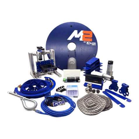
Makermade M2 User manual

SETTING UP YOUR
M2 AUTOMATED CUTTING MACHINE KIT
The complete beginner assembly guide by
Last Updated 11.09.2020 v1.14

2
M2 ASSEMBLY GUIDE
SETTING UP YOUR M2
TABLE OF CONTENTS
SECTION 1. Introduction - 3
SECTION 2. Parts Needed - 4
SECTION 3. Assembling the M2 - 7
SECTION 4. Building the Frame - 13
SECTION 5. Calibrating with Makerverse - 23
SECTION 6.Appendix - 42
This work is licensed under the creative commons Attribution
NonCommercial-NoDerivatives 4.0 International license. Last Updated 11.09.2020
Version 1.14

3
M2 ASSEMBLY GUIDE
Thanks for buying the M2 CNC Automated Cutting Machine by Maker Made! The following
instructions are intended for beginners - with no prior CNC experience. We’ll be releasing an
upgrade guide, as well as a paired down guide for experienced users soon.
Here are some notes on the layout:
1. First off, I’m Drew and I took the lead on creating this guide. My notes are tips and tricks to
help you along. They are in a different font, blue, and look like this:
They are meant to anwser some of the “why” questions you might have and give you tips to
get started. We suggest printing the guide in color, if you want a paper copy.
2. Setting up the M2 can be broken down into three main parts: building the M2, building the
frame (or mounting it on an existing Maslow frame), and calibration.
3. Since this guide is aimed at beginners, the calibration section also contains operation
instructions. Then you’ll know the whole process from creating a digital file to cutting it out
on your M2!
If you have experience with the Maslow, the M2’s older brother, you can use your existing
frame! Just follow the steps to build the M2 and skip the part on Easel to learn how to
calibrate with Makerverse.
We hope you enjoy setting up your kit and check out our Resources page for support and links
to our community. Happy making!
Drew’s Note: Let us know how this guide can be improved for beginners. We love to hear from you!
SECTION 1. INTRODUCTION
This work is licensed under the creative commons Attribution
NonCommercial-NoDerivatives 4.0 International license. Last Updated 11.09.2020
Version 1.14

4
M2 ASSEMBLY GUIDE
This section contains information on what came with your M2 and other tools you will need to building and
operation.
Drew’s Note: Check out the M2 Video Playlist for an overview of what’s in the box and other how to videos!
You’ll have to supply your own router for your M2. Here is the recommended list:
Router Clamp Size Maker Made Tested Community Tested
Bosch Colt 1hp (PR20EVSK) 71mm (included with M2) Yes Yes
Bosch 2.25hp
(1617EVS)
91mm (included in M2 Upgrade
Kit)
Yes Yes
DeWalt 611 1.25hp
(DWP611)
71mm (included with M2) Recommended Yes
DeWalt 618 2.25
(DW618M)
91mm (included in M2 Upgrade
Kit)
Yes Yes
Makita 1.25hp
(RT0701C)
71mm (with 3D printed adapter) Yes Yes
Ridgid 2hp
(R2202)
91mm (included in M2 Upgrade
Kit)
Yes Yes
Ridgid 2hp
(R22002)
91mm (included in M2 Upgrade
Kit)
Yes Yes
Tools needed for building your M2 and frame
(that didn’t come with you kit):
10mm Combo Wrench
13mm Combo Wrench
Phillips Screwdriver/ drill
Hammer
2 Standard Sized Bricks (to that attach to the M2 for cutting)
Clamps
Speed Square
Safety Goggles
The following is what came in your M2 kit!
SECTION 2. PARTS NEEDED
Item
2”x4”x8’ Board
2”x4”x10’ Board
1”x6”x8’ Board
4’x8’x3/4” Plywood or MDF
Quantity
2
1
2
1
Use
Frame Legs
Top Beam
Footer
Wasteboard
Wood required for wall-mounted frame (not
needed if you already have a frame):
This work is licensed under the creative commons Attribution
NonCommercial-NoDerivatives 4.0 International license. Last Updated 11.09.2020
Version 1.14

5
M2 ASSEMBLY GUIDE
DUE v1.2 Control Board, Shield,
and case
10’ MicroUSB to USB cord AC/DC Power Adapter and cord X, Y, and Z Axis Motors
(ETONM) (3)
X, Y, and Z Motor Power Cables
(JST XH 6 pin x2, (JST XH 6 pin
to PH 6 pin x1)
Motor Mounting Brackets (2) Stud Mounts (4) with shock
absorption strip
M Ring Carriage
Roller Bearing Carriges (2) Z-Axis Mount L-Brackets (3) Z-Axis Assembly Sled
Router Clamp Roller Bearings (4) Chains 335cm/11’ (2) Dust Collection Elbow
Spring Maker Made Router Bit Starter
Set
Maker Made Sticker, marker,
welcome note, and USB Drive
Bag A
WHAT’S IN THE BOX?
This work is licensed under the creative commons Attribution
NonCommercial-NoDerivatives 4.0 International license. Last Updated 11.09.2020
Version 1.14

6
M2 ASSEMBLY GUIDE
Bag B Bag C Bag D Bag E
Bag F Bag G Bag H Bag Z
Drew’s Note: Listed here are the contents of the bags. In the assembly portion, they will be refered to by their letter and number!
Bag A
A1. Cotter pins (2)
A2. Chain sprocket (2)
A3. Small nails (2)
A4. Large nails (2)
A5. White spacers (2)
Bag B
B1. Quick links (2)
B2. Small screws (4)
B3. Zip ties
Bag C
C1. Brick mounts (2)
C2. Large carriage bolts (4)
C3. Washers (4)
C4 Wingnuts (2)
C5. Locking nuts (2)
Bag D
D1. Shorter black wood screws
D2. Longer silver wood screws
Bag E
E1. Motor gear (2)
E2. Grub Screws (2)
E3. Motor screws (8)
E4. Motor washers (8)
E5. 3mm Allen wrench
Bag F
F1. Shoulder bolt (4)
F2. Large washer (8)
F3. Large locking nut (4)
F4. 5mm Allen wrench
Bag G
G1. Tiny wood screws (18)
G2. Small black M3 bolts (6)
G3. Wingnuts (6)
Bag H
H1. Z Motor bracket H2. Large Gear
H3. Grub screws (2) H4. Small Gear
H5. Small grub screws (2)
H6. M4 x16mm bolts (4)
H7. Black M3 x8mm bolts (6)
H8. Belt H9. 2.5mm Allen wrench
H10 2mm Allen wrench
Bag Z
Z1. L-bracket (4)
Z2. M5 x20mm (2)
Z3. M5 x10mm (8)
Z4. M5 T-nuts (8)
Z5. 3mm Allen wrench
Z6. (Alt) 6 screws
This work is licensed under the creative commons Attribution
NonCommercial-NoDerivatives 4.0 International license. Last Updated 11.09.2020
Version 1.14

7
M2 ASSEMBLY GUIDE
The M2 kit comes in several pieces to assemble. It can be split into four main parts: Sled
assembly, attaching belts and motor to Z-Axis Assembly, finishing the M2 assembly, and
centering your router.
Drew’s Note: We recommend reading this entire section before beginning.
Check out this video on how to build the M2!
ASSEMBLING YOUR M2
This work is licensed under the creative commons Attribution
NonCommercial-NoDerivatives 4.0 International license. Last Updated 11.09.2020
Version 1.14

8
M2 ASSEMBLY GUIDE
1. Attach three L-brackets to Sled by aligning with six small
predrilled holes, tall side toward center, using Phillips
screwdriver and G1 screws.
2. Attach three L-brackets to rectangular brackets on ring. Insert
G2 bolts from inside of ring bracket out through L-brackets, two
per bracket and secure with G3 wingnuts.
3. Hang both bearing carrige mounts by placing on each side of
attached ring.
4. Assemble both roller bearing carriages by feeding F1 bolt
through carriage, then F2 washer, then bearing, then F2 washer,
out through the other end of the carriage, and attach with F3 nut.
Use F4 Allen wrench on one end and 13mm combo wrench on the
other to tighten.
5. Peal off protective paper from acrylic dust cover. 6. Attach both C1 brick mounts by inserting C2 bolt from bottom,
with C3 washer and C4 wingnuts. Repeat on other side with C5
nut using 10mm combo wrench.
M2 ASSEMBLY PART 1: SLED ASSEMBLY (BAG C, BAG F, BAG G)
Shoulder
bolt
Ring
bearing
Washer
Washer
Nut
TOP VIEW SIDE VIEW
Drew’s Note: You can install
the bricks in this step, but
another, easier option is to
attach the bricks to the sled
after you have hung the M2
from the chains in the center of
your wasteboard.
This work is licensed under the creative commons Attribution
NonCommercial-NoDerivatives 4.0 International license. Last Updated 11.09.2020
Version 1.14

9
M2 ASSEMBLY GUIDE
1. Attach H1 Z motor bracket, but do not fully tighten (will
tighten fully in Step 6), using H6 bolts and H9 Allen Wrench.
2. Attach Z motor to H1, with the motor shaft in the slot farthest
from assembly, rotated with it’s bottom plug also toward the
outside. Use H7 bolts and H9 Allen Wrench.
3. Attach H2 large gear to motor, just above shaft base, ensuring
one H3 large grub screw is on flat side of motor shaft. Attach
with H3 grub screws (also called set screws) using H9 Allen
Wrench.
4. Line up small H4 Z-axis gear on lead screw, flush with gears on
H3, tighten with 2 smaller H5 grub screws using smaller H10 Allen
Wrench.
5. Loop H8 belt around gears, ensuring belt is level between
gears.
6. Tighten belt by gripping Z-axis motor and pulling toward
yourself until the belt is very tight. Use your other hand to
tighten the Z motor bracket with H9 Allen wrench.
M2 ASSEMBLY PART 2: ATTACH BELTS AND MOTOR TO Z-AXIS ASSEMBLY (BAG H)
Drew’s Note: Be sure that your
belt is tight! If the belt is loose,
your M2 will not move properly.
This work is licensed under the creative commons Attribution
NonCommercial-NoDerivatives 4.0 International license. Last Updated 11.09.2020
Version 1.14

10
M2 ASSEMBLY GUIDE
Drew’s Note: Updating products is especially during these times.
We currently have two active M2 versions that you may have
recieved. This page is for the first version, the next is version B.
Check out Step 1 to see which version you have and you’ll be good
from there. We appreciate your patience.
1. If your sled has rails attached, as seen below, skip to the next
page. If not, go to step 2A.
2A. Attach router clamp to Z-Axis Assembly using bolts screwed
into clamp. Attach as shown with Z5 Allen wrench.
Drew’s Note: The Z-Axis Assembly attaches to the sled with
T-nuts. They are marvels of engineering that are specially
designed to turn sideways when being tightened. This fastens
parts to aluminum extrusions at different angles. Sometimes, you
have to loosen and retighten them to get them to turn.
3A. Mount Z-Axis assembly to sled by inserting six Z6 screws in
Bag Z through bottom. Loosely attach using Z4 T-nuts.
4A. Turn T-nuts parallel with dust cover acrylic. Slide Z-Axis
assembly over t-nuts, and align router clamp with center hole.
Tighten T-nuts with Phillips screwdriver. Go to Part 4.
M2 ASSEMBLY PART 3: FINISH M2 Z-AXIS ASSEMBLY (BAG Z)
This work is licensed under the creative commons Attribution
NonCommercial-NoDerivatives 4.0 International license. Last Updated 11.09.2020
Version 1.14

11
M2 ASSEMBLY GUIDE
Drew’s Note: The Z-Axis Assembly attaches to the sled with
T-nuts. They are marvels of engineering that are specially
designed to turn sideways when being tightened. This fastens
parts to aluminum extrusions at different angles. Sometimes, you
have to loosen and retighten them to get them to turn.
2B. Mount Z-Axis assembly to sled by aligning extrusion “legs”
with the two rail “feet” that are already attached to the sled.
3B. Line up leg extrusions with side-threaded holes and bolt to
rail foot extrusions on each side. Slide extrusion legs onto rail
feet until it threaded holes line up on the side.
4B. Insert longer Z2 bolts into holes on each side to secure.
Tighten using Z5 Allen Wrench.
5B. Attach four Z1 L-brackets to each side of the extrusion legs.
Ensure that they turn 90 degrees. Use two Z4 T-Nuts and shorter
Z3 bolts per bracket using Z5 Allen wrench.
6B. Attach router clamp to Z-Axis Assembly using bolts screwed
into clamp. Attach as shown with Z5 Allen Wrench.
M2 ASSEMBLY PART 3B: FINISH M2 Z-AXIS ASSEMBLY (BAG Z)
Rail Foot Extrusion Leg
This work is licensed under the creative commons Attribution
NonCommercial-NoDerivatives 4.0 International license. Last Updated 11.09.2020
Version 1.14

12
M2 ASSEMBLY GUIDE
1. Attach router bit to router, insert into router clamp, and
tighten clamp with Z5 Allen Wrench.
2. Loosen bottom T-nuts with Phillips screwdriver and move sled
back and forth until router bit is alligned with exact center of M2
sled hole.
3. Tighten T-nuts on bottom and ensure they turned b ypopping
off the end caps on the rail feet. You can look down the rail and
see them turned. Replace the caps.
4. Check all of the bolts and T-nuts on your Z-Axis Assembly.
During shipping and use, bolts can vibrate loose. Pay special
attention to the grub screws that hold the Z-axis bearings in
place on the top and bottom of the lead screw.
5. Plug in Z-axis motor plug in Z-axis motor by pulling cord from
bottom of waste board to keep it out of the way while cutting.
6. Attach PVC dust collection elbow under Z-axis motor.
M2 ASSEMBLY PART 4: CENTERING YOUR ROUTER AND FINAL STEPS
Drew’s Note: It’s supposed
to be a snug fit to keep scraps
from flying everywhere.
Check out our M2 Resources
and Maker Marketplace for
dust collection ideas!
Drew’s Note: It’s very important
that the router bit is in the
exact center of M2 hole! All of
the triangulation math for the
M2’s GRBL code is based of the
assumption that your bit is in the
exact center. If it is off, even by a
few millimeters, it will result in your
M2 cutting incorrectly.
Drew’s Note: Use enclosed
zip ties for cord maintenance!
This work is licensed under the creative commons Attribution
NonCommercial-NoDerivatives 4.0 International license. Last Updated 11.09.2020
Version 1.14

13
M2 ASSEMBLY GUIDE
BUILDING YOUR FRAME
This Section is how to build your frame for your M2. It is split into sseven main sections: Arduino DUE board setup, building
the wasteboard, mounting the top beam, placing the material, attaching the motors, attaching the chains, and mounting your
M2.
Drew’s Note: We recommend reading this entire section before beginning.
This work is licensed under the creative commons Attribution
NonCommercial-NoDerivatives 4.0 International license. Last Updated 11.09.2020
Version 1.14

14
M2 ASSEMBLY GUIDE
1. Using included B2 screws, mount controlbBoard in its case to the wall behind Wasteboard, helps to mount in middle for motor
wires to reach.
Drew’s Note: If you’re mounting without case or need to modify for any reason, this is how to attach the top Control Shield to
bottom DUE board. Line up the pins as shown and be careful they don’t bend
BUILDING YOUR FRAME PART 1: MOUNT ARDUINO DUE BOARD AND SHIELD
Drew’s Note: The M2’s brain is an Arduino DUE microcontroller. We recommend mounting the DUE to the wall behind your
Wasteboard, but it can be mounted in any safe location where it won’t be stepped on or conflict with the M2 during operation.
With case, wire plugs on bottom.
Bottom DUE board, without case (notice how the “DUE”
written on the board is up). That is the orientation for this
instruction, the bottom power is unused.
Pin Alignment Bottom View Top View
This work is licensed under the creative commons Attribution
NonCommercial-NoDerivatives 4.0 International license. Last Updated 11.09.2020
Version 1.14

15
M2 ASSEMBLY GUIDE
2. Plug in wires, USB, and power. Use B3 zip ties for cord maintenance.
Drew’s Note: A high-pitched whine is normal! That means your DUE board is receiving power. It will get louder when connected to
a computer. The following steps will explain where the other ends of the cords go.
Power
3. Right Motor
Drew’s Note: If your case looks like this, it needs to be modified. Note
the small power port. You will have to plug in the power with the top of
the case off, or cut the hole larger. We appologize for this mistake in
the first run of the M2 and it will be fixed in later versions.
1. Left Motor 2. Z-Motor
(longest cord,
will connect to M2)
Future J Tech
Laser Connection
1. 2. 3.
Power
Correct
MicroUSB
port
Example of connection
not fully seated!
2
1
This work is licensed under the creative commons Attribution
NonCommercial-NoDerivatives 4.0 International license. Last Updated 11.09.2020
Version 1.14

16
M2 ASSEMBLY GUIDE
The first step to starting your M2 CNC adventure is to build the frame that will hold your material and the M2
while it cuts. The M2 mounts for your frame are included, but you will need to purchase the following from a local
hardware store to build the standard 4x8’ frame. If you already have a Maslow frame, you’re good to go!
Wood needed:
BUILDING YOUR FRAME PART 2: WASTEBOARD (BAG D)
Item
2”x4”x8’ Board
2”x4”x10’ Board
1”x6”x8’ Board
4’x8’x3/4” Plywood or MDF
Quantity
2
1
2
1
Use
Frame Legs
Top Beam
Footer
Wasteboard
The Frame has 2 main parts: The Top Beam that holds the motors and the Wasteboard on
which you will clamp or screw the material you want to the M2 to cut.
Drew’s Note: The size of material the M2 can cut is only limited by the chain length. These instructions are based on the chain
included with your M2 and will walk you through how to set up your kit to cut material almost to the edge of the 4x8’ space. These
instructions are based on attaching the Top Beam to a wall. If you are intersted in a different frame size or design, check out our
M2 Resources page or the Owners group on Facebook for help!
1. To build the wasteboard, cut the 2 4”x4”x8’ boards in half.
2. Line all four boards up and measure up 1’ from bottom. Use a speed square to draw a line.
3. Line up 4 legs on 1”x6”x8” board and attach with D1 screws underneath line. This will
ensure your wasteboard is 12” from the ground.
ASSEMBLY GUIDE CONT.
Step 4: Attach Footer to Legs
304.8mm [12in]
228.6mm [9in] 2X 228.6mm [9in]
Step 5: Attach Wasteboard to Legs
6pcs long wood
screws in Bag D
63.5mm [2.5in]
4pcs long wood
screws in Bag D
38.1mm [1.5in]
165.1mm [6.5in]
Rest Wasteboard
on Footer
Drew’s Note: The three most important things to keep in mind when building the frame are 1. The bottom of your
wasteboard should be 12” from the bottom of your footers. 2. The wasteboard should be clamped or screwed onto
the stud mounts, to maintain a 15 degree angle. 3. The target distance of the motor offset (from the top of the chain
to the top of the wasteboard, should be at least 18” for a 4’x8’ frame.
ASSEMBLY GUIDE CONT.
Step 4: Attach Footer to Legs
304.8mm [12in]
228.6mm [9in] 2X 228.6mm [9in]
Step 5: Attach Wasteboard to Legs
6pcs long wood
screws in Bag D
63.5mm [2.5in]
4pcs long wood
screws in Bag D
38.1mm [1.5in]
165.1mm [6.5in]
Rest Wasteboard
on Footer
ASSEMBLY GUIDE CONT.
Step 4: Attach Footer to Legs
304.8mm [12in]
228.6mm [9in] 2X 228.6mm [9in]
Step 5: Attach Wasteboard to Legs
6pcs long wood
screws in Bag D
63.5mm [2.5in]
4pcs long wood
screws in Bag D
38.1mm [1.5in]
165.1mm [6.5in]
Rest Wasteboard
on Footer
This work is licensed under the creative commons Attribution
NonCommercial-NoDerivatives 4.0 International license. Last Updated 11.09.2020
Version 1.14

17
M2 ASSEMBLY GUIDE
ASSEMBLY GUIDE CONT.
Step 4: Attach Footer to Legs
304.8mm [12in]
228.6mm [9in] 2X 228.6mm [9in]
Step 5: Attach Wasteboard to Legs
6pcs long wood
screws in Bag D
63.5mm [2.5in]
4pcs long wood
screws in Bag D
38.1mm [1.5in]
165.1mm [6.5in]
Rest Wasteboard
on Footer
ASSEMBLY GUIDE CONT.
Step 4: Attach Footer to Legs
304.8mm [12in]
228.6mm [9in] 2X 228.6mm [9in]
Step 5: Attach Wasteboard to Legs
6pcs long wood
screws in Bag D
63.5mm [2.5in]
4pcs long wood
screws in Bag D
38.1mm [1.5in]
165.1mm [6.5in]
Rest Wasteboard
on Footer
ASSEMBLY GUIDE CONT.
Step 4: Attach Footer to Legs
304.8mm [12in]
228.6mm [9in] 2X 228.6mm [9in]
Step 5: Attach Wasteboard to Legs
6pcs long wood
screws in Bag D
63.5mm [2.5in]
4pcs long wood
screws in Bag D
38.1mm [1.5in]
165.1mm [6.5in]
Rest Wasteboard
on Footer
BUILDING YOUR FRAME PART 2: BUILDING THE WASTEBOARD (BAG D)
4. Set the 4’x8’ Wasteboard to the legs and rest it on the footer. Attache to legs with D1
screws. This will help to flatten your wasteboard for smother cuts.
92 "
Step 1: Attach Stud Mounts to wall
65 3
4" up from floor
(a) Find stud and attach
first Stud Mount using 2pcs
long wood screws in Bag D
(b) Attach Stud Mount
using 2 drywall anchors
and 2pcs long wood
screws in Bag D
Step 2: Mount Top Beam to Stud Mounts on wall
ASSEMBLY GUIDE
Use 8pcs short wood screws in Bag D to attach top beam
Step 3: Attach last two Stud Mounts
146mm [5.75in]
146mm [5.75in]
Stud Mounts directly below
first Stud Mounts
5. Lean the wasteboard against your wall of choice. Measure wall studs and where
top of wasteboard leans on wall. Attach stud mounts for wasteboard, with larger
ends closer to the ground, so that the wasteboard will lean on them at the desired
15 degree angle. Use D2 screws.
92 "
Step 1: Attach Stud Mounts to wall
65 3
4" up from floor
(a) Find stud and attach
first Stud Mount using 2pcs
long wood screws in Bag D
(b) Attach Stud Mount
using 2 drywall anchors
and 2pcs long wood
screws in Bag D
Step 2: Mount Top Beam to Stud Mounts on wall
ASSEMBLY GUIDE
Use 8pcs short wood screws in Bag D to attach top beam
Step 3: Attach last two Stud Mounts
146mm [5.75in]
146mm [5.75in]
Stud Mounts directly below
first Stud Mounts
This work is licensed under the creative commons Attribution
NonCommercial-NoDerivatives 4.0 International license. Last Updated 11.09.2020
Version 1.14

18
M2 ASSEMBLY GUIDE
5. Lean your wasteboard against the stud mounts from step two. Measure 10” up from the top of your wasteboard on the
wall. This will be the height of the bottom of the top beam mounts. This will give you the required 18” distance between your
wasteboard and the top of the chain.
6. Mount top beam to wall studs, careful to measure each side exactly the same amount from the floor.
Drew’s Note: Pay close attention that the stud mounts are mounted the exact distance from the floor! Even a few millimeters can
through off your claibration and cause slanting cuts.
1. Measure wall studs for stud mounts that will hold the top beam, with the larger ends closer to the ground.
92 "
Step 1: Attach Stud Mounts to wall
65 3
4" up from floor
(a) Find stud and attach
first Stud Mount using 2pcs
long wood screws in Bag D
(b) Attach Stud Mount
using 2 drywall anchors
and 2pcs long wood
screws in Bag D
Step 2: Mount Top Beam to Stud Mounts on wall
ASSEMBLY GUIDE
Use 8pcs short wood screws in Bag D to attach top beam
Step 3: Attach last two Stud Mounts
146mm [5.75in]
146mm [5.75in]
Stud Mounts directly below
first Stud Mounts
BUILDING YOUR FRAME PART 3: BUILDING THE TOP BEAM (BAG D)
2. Attach stud mounts to 10’ top beam with D1 screws. Ensure that they are the same distance up from the bottom of your beam.
Pilot holes 0.5” from the bottom can help
Drew’s Note: Pay close attention that the stud mounts are mounted in the exact plane on your top beam! even a few millimeters can
through off your claibration.
92 "
Step 1: Attach Stud Mounts to wall
65 3
4" up from floor
(a) Find stud and attach
first Stud Mount using 2pcs
long wood screws in Bag D
(b) Attach Stud Mount
using 2 drywall anchors
and 2pcs long wood
screws in Bag D
Step 2: Mount Top Beam to Stud Mounts on wall
ASSEMBLY GUIDE
Use 8pcs short wood screws in Bag D to attach top beam
Step 3: Attach last two Stud Mounts
146mm [5.75in]
146mm [5.75in]
Stud Mounts directly below
first Stud Mounts
7. Attach motor mounts on each edge of the top beam, flush with each end. One screw on front and 4 on top using D1 wood screws.
234.95mm [9.25in]
273.05mm [10.75in]
63.5mm [2.5in]
4pcs long
wood screws
in Bag D
Attach Motor Mounts on
top edge of Top Beam,
flush with edges
342.91mm [13.5in]
Clamp or Screw
Assembly to
lower Stud
Mounts
2pcs long wood screws in Bag D
234.95mm [9.25in]
273.05mm [10.75in]
63.5mm [2.5in]
4pcs #6 x 2 1
2"
Wood Screw
Attach Motor Mounts on
top edge of Top Beam,
flush with edges
342.91mm [13.5in]
Clamp Assembly
to lower Stud
Mounts
2pcs #6 x 2 1
2" Wood Screws
A
A (1:4)
(Enlarged view)
This work is licensed under the creative commons Attribution
NonCommercial-NoDerivatives 4.0 International license. Last Updated 11.09.2020
Version 1.14

19
M2 ASSEMBLY GUIDE
BUILDING YOUR FRAME PART 4: PLACE MATERIAL
The material you are cutting will need to by clamped to the wasteboard stud mounts on the top, or screwed
into the wasteboard.
Drew’s Note: Always clamp or screw the material you’re cutting to the Wasteboard Stud Mounts so it doesn’t
move.
This work is licensed under the creative commons Attribution
NonCommercial-NoDerivatives 4.0 International license. Last Updated 11.09.2020
Version 1.14

20
M2 ASSEMBLY GUIDE
BUILDING YOUR FRAME PART 5: MOUNT MOTORS TO FRAME (BAG E)
1. Place motor in left bracket, with cylindrical end toward center.
Slide lock E4 washers over E3 screws and fasten screws through
the front of the motor with a Phillips Screwdriver.
2.Attach E1 motor gear by inserting the E2 grub screw into the
gear hole, aligning with the flat side of the motor shaft, and
tightening with E5 Allen wrench to prevent slipping.
3. Plug six-pin motor wire into motor, connection will only seat
in one direction. Ensure connection is secure and use one of the
shorter blue wires.
4. Repeat steps 1-3 on right side.
Drew’s Note: The X and Y motors move the M2 back and forth on the frame. If one of your motors
of your M2 doesn’t move during operation, or the M2 generally moves in a strange direction, the first
thing to check are the motor connections. If the wires connecting the X, Y, and Z motors are loose, even
a tiny bit, it will cause your M2 to malfunction.
This work is licensed under the creative commons Attribution
NonCommercial-NoDerivatives 4.0 International license. Last Updated 11.09.2020
Version 1.14
Other manuals for M2
3
This manual suits for next models
1
Table of contents
Other Makermade Cutter manuals
