Makita 9526PB User manual

DOUBLE
INSULATION
100 mm 9526PB
115 mm 9527PB
125 mm 9528PB
Angle Grinder

2
SPECIFICATIONS
Model 9526PB 9527PB 9528PB
No load speed (min-1) ........................................... 11,000 11,000 11,000
Overall length ........................................................ 275 mm 275 mm 275 mm
Net weight ............................................................. 1.5 kg 1.5 kg 1.5 kg
Spindle thread ....................................................... M10 M14 M14
• Due to our continuing programme of research and development, the specifications herein are subject to change with-
out notice.
• Note: Specifications may differ from country to country.
Intended use
The tool is intended for cutting, grinding and sanding of metal and stone materials without the use of water.
Power supply
The tool should be connected only to a power supply of the same voltage as indicated on the nameplate, and can only
be operated on single-phase AC supply. They are double-insulated in accordance with European Standard and can,
therefore, also be used from sockets without earth wire.
For European countries only
Noise and Vibration
ENH003-1
The typical A-weighted sound pressure level is 84 dB (A).
The noise level under working may exceed 85 dB (A).
– Wear ear protection. –
The typical weighted root mean square acceleration
value is not more than 2.5 m/s2.
EC-DECLARATION OF CONFORMITY
ENH001-1
We declare under our sole responsibility that this product
is in compliance with the following standards of standard-
ized documents,
HD400, EN50144, EN55014, EN61000
in accordance with Council Directives, 73/23/EEC,
89/336/EEC and 98/37/EC.
Yasuhiko Kanzaki
CE 2004
Director
MAKITA INTERNATIONAL EUROPE LTD.
Michigan Drive, Tongwell, Milton Keynes,
Bucks MK15 8JD, ENGLAND

3
12
34
56
78
3
1
2
9526PB 9527PB, 9528PB
3
2
1
4
5
6
8
7
4
9
6
10
11 1312
4
9
6
10

4
910
11
Symbols
The followings show the symbols used for the tool. Be sure that you understand their meaning before use.
❏Read instruction manual.
❏DOUBLE INSULATION
❏Wear safety glasses.
❏Only for EU countries
Do not dispose of electric equipment together with household waste material!
In observance of European Directive 2002/96/EC on waste electrical and electronic equipment and its
implementation in accordance with national law, electric equipment that have reached the end of their life
must be collected separately and returned to an environmentally compatible recycling facility.
15
16
14

5
ENGLISH
Explanation of general view
1 Wheel guard
2 Bearing box
3 Screw
4 Lock nut
5 Depressed center wheel
6 Inner flange
7 Lock nut wrench
8 Shaft lock
9Diamondwheel
10 Spindle
11 Lock-off button
12 Switch trigger
13 Lock-on button
14 Limit mark
15 Screwdriver
16 Brush holder cap
SAFETY INSTRUCTIONS
Warning! When using electric tools, basic safety pre-
cautions should always be followed to reduce the
risk of fire, electric shock and personal injury, includ-
ing the following. Read all these instructions before
attempting to operate this product and save these
instructions.
For safe operation:
1. Keep work area clean
Cluttered areas and benches invite injuries.
2. Consider work area environment
Don’t expose power tools to rain. Don’t use power
tools in damp or wet locations. Keep work area well
lit. Don’t use power tools in presence of flammable
liquids or gases.
3. Guard against electric shock
Prevent body contact with grounded surfaces
(e.g. pipes, radiators, ranges, refrigerators).
4. Keep children away
Do not let visitors contact tool or extension cord.
All visitors should be kept away from work area.
5. Store idle tools
When not in use, tools should be stored in dry, high,
or locked-up place, out of the reach of children.
6. Don’t force tool
It will do the job better and safer at the rate for which
it was intended.
7. Use right tool
Don’t force small tools or attachments to do the job
of a heavy duty tool. Don’t use tools for purposes not
intended; for example, don’t use circular saw for cut-
ting tree limbs or logs.
8. Dress properly
Do not wear loose clothing or jewellery. They can be
caught in moving parts. Rubber gloves and non-skid
footwear are recommended when working outdoors.
Wear protective hair covering to contain long hair.
9. Use safety glasses and hearing protection
Also use face or dust mask if cutting operation is
dusty.
10. Connect dust extraction equipment
If devices are provided for the connection of dust
extraction and collection facilities, ensure these are
connected and properly used.
11. Don’t abuse cord
Never carry tool by cord or yank it to disconnect it
from receptacle. Keep cord from heat, oil and sharp
edges.
12. Secure work
Use clamps or a vice to hold work. It’s safer than
using your hand and it frees both hands to operate
tool.
13. Don’t overreach
Keep proper footing and balance at all times.
14. Maintain tools with care
Keep tools sharp and clean for better and safer per-
formance. Follow instructions for lubricating and
changing accessories. Inspect tool cords periodi-
cally and, if damaged, have repaired by authorised
service facility. Inspect extension cords periodically
and replace if damaged. Keep handles dry, clean
and free from oil and grease.
15. Disconnect tools
When not in use, before servicing, and when chang-
ing accessories such as blades, bits and cutters.
16. Remove adjusting keys and wrenches
Form the habit of checking to see that keys and
adjusting wrenches are removed from tool before
turning it on.
17. Avoid unintentional starting
Don’t carry plugged-in tool with finger on switch.
Be sure switch is off when plugging in.
18. Outdoor use extension cords
When tool is used outdoors, use only extension
cords intended for use outdoors and so marked.
19. Stay alert
Watch what you are doing. Use common sense.
Do not operate tool when you are tired.
20. Check damaged parts
Before further use of the tool, a guard or other part
that is damaged should be carefully checked to
determine that it will operate properly and perform
its intended function. Check for alignment of moving
parts, binding of moving parts, breakage of parts,
mounting, and any other conditions that may affect
its operation. A guard or other part that is damaged
should be properly repaired or replaced by an
authorised service centre unless otherwise indicated
elsewhere in this instruction manual. Have defective
switches replaced by and authorised service centre.
Do not use tool if switch does not turn it on and off.
21. Warning
The use of any other accessory or attachment other
than recommended in this operating instruction or
the catalogue may present a risk of personal injury.
22. Have your tool repaired by an expert
This electric appliance is in accordance with the rel-
evant safety rules. Repairing of electric appliances
may be carried out only by experts otherwise it may
cause considerable danger for the user.

6
ADDITIONAL SAFETY RULES
ENB031-5
1. Always use eye and ear protection. Other per-
sonal protective equipment such as dust mask,
gloves, helmet and apron should be worn when
necessary. If in doubt, wear the protective equip-
ment.
2. Always be sure that the tool is switched off and
unplugged before carrying out any work on the
tool.
3. Keep guards in place.
4. Use only wheels with correct size and wheels
having a maximum operating speed at least as
high as the highest No Load Speed marked on
the tool’s nameplate. When using depressed
center wheels, be sure to use only fiberglass-
reinforced wheels.
5. Check the wheel carefully for cracks or damage
before operation. Replace cracked or damaged
wheel immediately.
6. Observe the instructions of the manufacturer for
correct mounting and use of wheels. Handle and
store wheels with care.
7. Do not use separate reducing bushings or adap-
tors to adapt large hole abrasive wheels.
8. Use only flanges specified for this tool.
9. Do not damage the spindle, the flange (espe-
cially the installing surface) or the lock nut. Dam-
age to these parts could result in wheel
breakage.
10. For tools intended to be fitted with threaded hole
wheel, ensure that the thread in the wheel is long
enough to accept the spindle length.
11. Before using the tool on an actual workpiece,
test run the tool at the highest no load speed for
at least 30 seconds in a safe position. Stop
immediately if there is any vibration or wobbling
that could indicate poor installation or a poorly
balanced wheel. Check the tool to determine the
cause.
12. Check that the workpiece is properly supported.
13. Hold the tool firmly.
14. Keep hands away from rotating parts.
15. Make sure the wheel is not contacting the work-
piece before the switch is turned on.
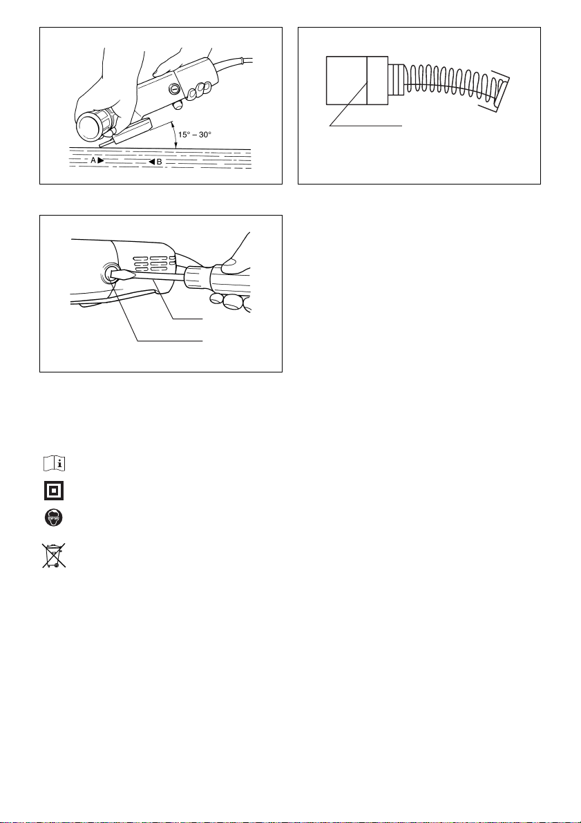
16. Use the specified surface of the wheel to per-
form the grinding.
17. Do not use cutting off wheel for side grinding.
18. Watch out for flying sparks. Hold the tool so that
sparks fly away from you and other persons or
flammable materials.
19. Pay attention that the wheel continues to rotate
after the tool is switched off.
20. Do not touch the workpiece immediately after
operation; it may be extremely hot and could
burn your skin.
21. Position the tool so that the power cord always
stays behind the tool during operation.
22. If working place is extremely hot and humid, or
badly polluted by conductive dust, use a short-
circuit breaker (30 mA) to assure operator safety.
23. Do not use the tool on any materials containing
asbestos.
24. Do not use water or grinding lubricant.
25. Ensure that ventilation openings are kept clear
when working in dusty conditions. If it should
become necessary to clear dust, first disconnect
the tool from the mains supply (use non metallic
objects) and avoid damaging internal parts.
26. When use cut-off wheel, always work with the
dust collecting wheel guard required by domes-
tic regulation.
27. Cutting discs must not be subjected to any lat-
eral pressure.
SAVE THESE INSTRUCTIONS.
OPERATING INSTRUCTIONS
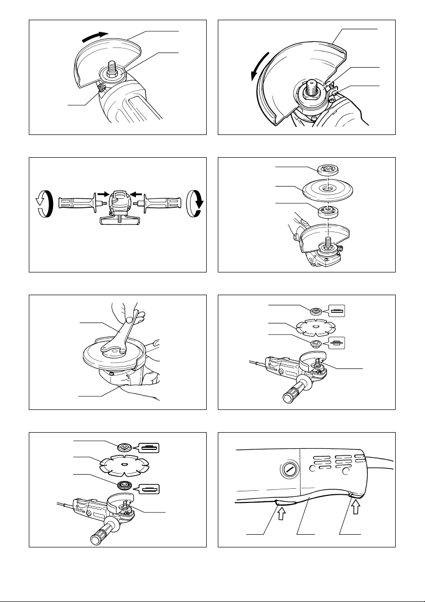
Installing the wheel guard (Fig. 1 & 2)
Mount the wheel guard with the tab on the wheel guard
band aligned with the notch on the bearing box. Then
rotate the wheel guard 180° clockwise (for 9526PB) or
counterclockwise (for 9527PB and 9528PB). Be sure to
tighten the screws securely.
Installing side grip (auxiliary handle) (Fig. 3)
For your own safety always use the side grip. The side
grip can be installed on either side of the tool.
Installing or removing the depressed center
wheel
CAUTION:
• Always be sure that the tool is switched off and
unplugged before installing or removing the wheel.
Mount the inner flange onto the spindle. Fit the wheel on
over the inner flange and screw the lock nut onto the
spindle. (Fig. 4)
To tighten the lock nut, press the shaft lock firmly so that
the spindle cannot revolve, then use the lock nut wrench
and securely tighten clockwise. (Fig. 5)
WARNING:
• Only actuate the shaft lock when the spindle is not
moving.
Installing or removing diamond wheel
(accessory) (Fig. 6 & 7)
CAUTION:
• Make sure that the arrow on the tool should point in the
same direction as the arrow on the diamond wheel.
Mount the inner flange onto the spindle. Fit the diamond
wheel on over the inner flange and screw the lock nut
onto the spindle. Notice that flat side of the lock nut
should face the diamond wheel in case the diamond
wheel is used.
Switch action (Fig. 8)
CAUTION:
• Do not pull the switch trigger forcibly without pushing in
the lock-off button.
• Before plugging in the tool, always check to see that
the switch actuates properly and returns to the “OFF”
position when released.
To prevent the switch trigger from being accidentally
actuated, a lock-off button is provided. To start the tool,
push in the lock-off button and then pull the switch trig-
ger. Release the switch trigger to stop. For continuous
operation, pull the switch trigger and then push in the
lock-on button. To stop the tool from the locked position,
pull the trigger fully, then release it.

7
Operation (Fig. 9)
Hold the tool firmly with both hands. Turn the tool on and
then apply the wheel or disc to the workpiece.
In general, keep the edge of the wheel or disc at an angle
of about 15° – 30° to the workpiece surface. During the
break-in period with a new wheel, do not work the griader
in the B direction or it will cut into the workpiece. Once
the edge of the wheel has been rounded off by use, the
wheel may be worked in both A and B directions.
WARNING:
• It should never be necessary to force the tool. The
weight of the tool applies adequate pressure. Forcing
and excessive pressure could cause dangerous wheel
breakage.
• Continued use of a worn-out wheel may result in wheel
explosion and serious personal injury. Depressed cen-
ter wheel should not be used after it has been worn
down to 75 mm in diameter for Model 9526PB or 90 mm
for Models 9527PB and 9528PB in diameter. Use of the
wheel after this point is unsafe and it should be
removed from service and rendered unusable by inten-
tional destruction.
Operation with diamond wheel (accessory)
WARNING:
• Forcing and exerting excessive pressure or allowing
the wheel to bend, pinch or twist in the cut can cause
overheating of the motor and dangerous kickback of
the tool.
CAUTION:
• After cutting operation, make sure that the diamond
wheel stops revolving completely. Then, place the tool.
It is dangerous to place the tool before turning off the
tool. If there are dust or dirt around the tool, the tool
may suck in them.
Be sure that the wheel does not contact the workpiece.
Turn the tool on and hold the tool firmly. Wait until the
wheel attains full speed. Now simply move the tool for-
ward over the workpiece surface, keeping it flat and
advancing smoothly until the cutting is completed.
MAINTENANCE
CAUTION:
• Always be sure that the tool is switched off and
unplugged before attempting to perform inspection or
maintenance.
Replacing carbon brushes (Fig. 10 & 11)
Remove and check the carbon brushes regularly.
Replace when they wear down to the limit mark. Keep
the carbon brushes clean and free to slip in the holders.
Both carbon brushes should be replaced at the same
time. Use only identical carbon brushes.
Use a screwdriver to remove the brush holder caps. Take
out the worn carbon brushes, insert the new ones and
secure the brush holder caps.
To maintain product SAFETY and RELIABILITY, repairs,
any other maintenance or adjustment should be per-
formed by Makita Authorized or Factory Service Centers,
always using Makita replacement parts.
ACCESSORIES
CAUTION:
• These accessories or attachments are recommended
for use with your Makita tool specified in this manual.
The use of any other accessories or attachments might
present a risk of injury to persons. Only use accessory
or attachment for its stated purpose.
If you need any assistance for more details regarding
these accessories, ask your local Makita service center.
• Wheel cover
• Inner flange
• Depressed center wheels
• Lock nut
• Rubber pad
• Abrasive discs
• Lock nut 10 – 30 (For abrasive disc)
• Wire cup brush 75
• Wire bevel brush 85
• Diamond wheel

Makita Corporation
Anjo, Aichi, Japan
884047C226
Other manuals for 9526PB
4
This manual suits for next models
2
Table of contents
Other Makita Grinder manuals

Makita
Makita 9607BL User manual

Makita
Makita GA7011C User manual

Makita
Makita GA036G User manual

Makita
Makita DGA417RTE User manual

Makita
Makita BGD800 User manual

Makita
Makita GA7020 User manual

Makita
Makita DGA419 User manual

Makita
Makita GA5021 User manual

Makita
Makita 9005B User manual

Makita
Makita GA4031 User manual

Makita
Makita DGA412 User manual

Makita
Makita DGA700 User manual

Makita
Makita GA7020R User manual

Makita
Makita DGA417 Operating instructions

Makita
Makita 9564PC User manual

Makita
Makita M9502R User manual

Makita
Makita XAG16 User manual

Makita
Makita GA7020 User manual

Makita
Makita 9565PCV User manual

Makita
Makita GA9071 User manual