manuals.online logo
Brands
  1. Home
  2. •
  3. Brands
  4. •
  5. Makita
  6. •
  7. Grinder
  8. •
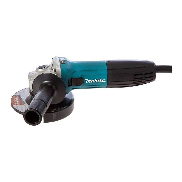
  9. Makita GA7060 Manual

Makita GA7060 Manual

Other manuals for GA7060

5

This manual suits for next models

7

Other Makita Grinder manuals

Makita 9564P User manual

Makita

Makita 9564P User manual

Makita 9069 Quick start guide

Makita

Makita 9069 Quick start guide

Makita GA7020R User manual

Makita

Makita GA7020R User manual

Makita 9556NB User manual

Makita

Makita 9556NB User manual

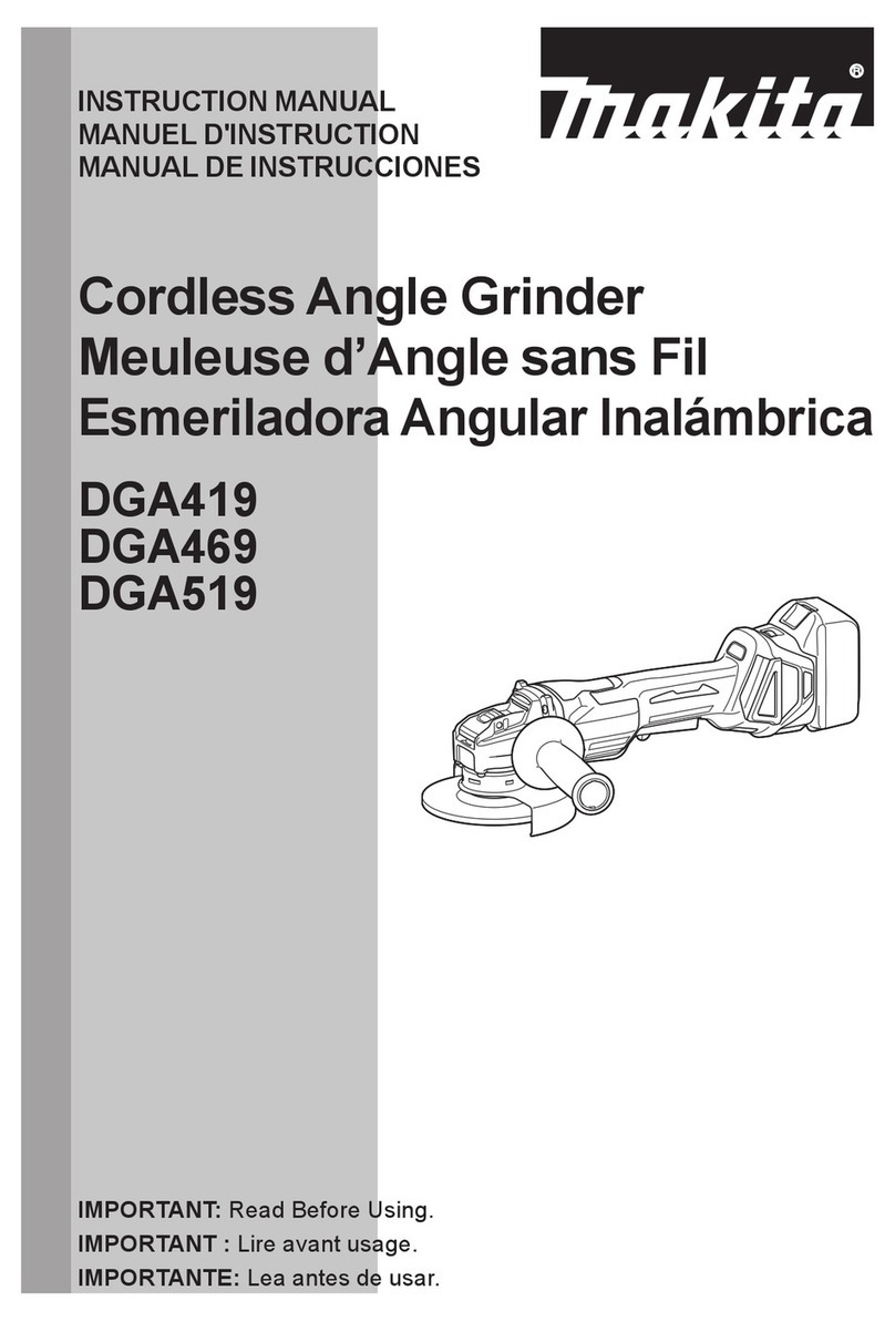
Makita GA4541C User manual

Makita

Makita GA4541C User manual

Makita 9067 User manual

Makita

Makita 9067 User manual

Makita XAG25 User manual

Makita

Makita XAG25 User manual

Makita GA011G User manual

Makita

Makita GA011G User manual

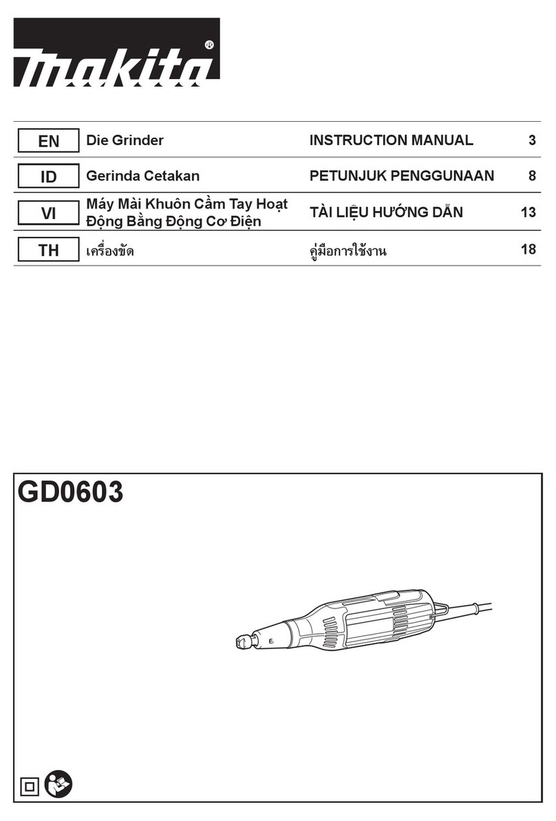
Makita GD0603 User manual

Makita

Makita GD0603 User manual

Makita GB602 User manual

Makita

Makita GB602 User manual

Makita GA5020 User manual

Makita

Makita GA5020 User manual

Makita 9566C Manual

Makita

Makita 9566C Manual

Makita 9557PB Quick start guide

Makita

Makita 9557PB Quick start guide

Makita 9558NBR User manual

Makita

Makita 9558NBR User manual

Makita 9077 User manual

Makita

Makita 9077 User manual

Makita GA5080 User manual

Makita

Makita GA5080 User manual

Makita GA4570 User manual

Makita

Makita GA4570 User manual

Makita 9015A User manual

Makita

Makita 9015A User manual

Makita M908 User manual

Makita

Makita M908 User manual

Makita GD0800C User manual

Makita

Makita GD0800C User manual

Makita GA021G User manual

Makita

Makita GA021G User manual

Makita 9306 User manual

Makita

Makita 9306 User manual

Makita DGA700 User manual

Makita

Makita DGA700 User manual

Makita DGA402 User manual

Makita

Makita DGA402 User manual

Popular Grinder manuals by other brands

Gude 20000 PRO Original operating instructions

Gude

Gude 20000 PRO Original operating instructions

Nesco FG-300 Care/use guide

Nesco

Nesco FG-300 Care/use guide

RIDGID R86047 Operator's manual

RIDGID

RIDGID R86047 Operator's manual

Holzmann MTY 8-70 user manual

Holzmann

Holzmann MTY 8-70 user manual

DeWalt DWE4557G instruction manual

DeWalt

DeWalt DWE4557G instruction manual

Meterk S1M-GW20-115 Translation of the original instructions

Meterk

Meterk S1M-GW20-115 Translation of the original instructions

U.S.SAWS SX65000C operating manual

U.S.SAWS

U.S.SAWS SX65000C operating manual

Parkside PWS 230 C3 Translation of the original instructions

Parkside

Parkside PWS 230 C3 Translation of the original instructions

SUHNER ABRASIVE ASC 9 Technical document

SUHNER ABRASIVE

SUHNER ABRASIVE ASC 9 Technical document

PTA P1322 Operation manual

PTA

PTA P1322 Operation manual

Craftsman CMCG400 instruction manual

Craftsman

Craftsman CMCG400 instruction manual

Crown CT13313 Original instructions

Crown

Crown CT13313 Original instructions

Parkside 280250 instructions

Parkside

Parkside 280250 instructions

Jet JPSG-618M1 Operating instructions and parts manual

Jet

Jet JPSG-618M1 Operating instructions and parts manual

DeWalt DWEN202 Original instructions

DeWalt

DeWalt DWEN202 Original instructions

Garrick BG8-UT instruction manual

Garrick

Garrick BG8-UT instruction manual

Grizzly G2790 instruction manual

Grizzly

Grizzly G2790 instruction manual

Fein MSf843-1a Original instructions

Fein

Fein MSf843-1a Original instructions

manuals.online logo
manuals.online logoBrands
  • About & Mission
  • Contact us
  • Privacy Policy
  • Terms and Conditions

Copyright 2025 Manuals.Online. All Rights Reserved.

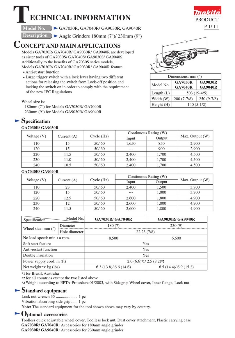
ECHNICAL INFORMATION
T
Model No.
Description
March 2016
CONCEPT AND MAIN APPLICATIONS
1 / 25
Specification
Standard equipment
GA7060, GA7060R, GA7061, GA7061R /
GA9060, GA9060R, GA9061, GA9061R
Angle Grinder 180mm (7") /
Angle Grinder 230mm (9")
These models have been developed for heavy duty applications
such as foundry grinding.
The motor is more durable than that of our existing models with
the following improvements:
・Design of anti layer short of Armature (Commutator and its wire
connected portion)
・Low-absorbent motor housing to reduce water absorption
・Adoption of spiral spring type Brush holders yet with a compact body
SJS II (Super joint system II) for GA7061, GA7061R, GA9061 and
GA9061R provides increased machine durability by absorbing
the vibration produced by the wheel grinding or cutting material.
Dimensions: mm (")
Width (W)
Height (H)
Length (L)
Model
450 (17-3/4)
200 (7-7/8)
144 (5-5/8)/
145 (5-3/4)
250 (9-7/8)
L
H
Continuous Rating (W)
Voltage (V) Cycle (Hz) Input Output Max Output (W)
110 15 1,65050/60
15 N/A50/60
10 2,20050/60
9.6 2,200
800
800
1,400
1,400
2,200
2,200
3,000
3,00050/60
120
230
240
10.5 2,20050/60 1,400 3,000220
Current (A)
Optional accessories
Anti vibration grip
Toolless lock nut
Dust cover attachment
Toolless wheel cover
W
Max thickness 6.5 (1/4)
Shock absorbing system Yes (SJS II)No
2.5 (8.2), 2.0 (6.6) for Brazil and Australia
Side grip
Lock nut wrench
Note: The standard equipment may vary by country or model variation.
Abrasive discs
Lock nut release socket
Plastic carrying case
*1 Triaxial vector sum. According to EN60745-2-3. *2 With Side grip, Wheel cover, Lock nut, Inner flange
Model No.
Specification
Soft start
Anti-restart function
Protection against electric shock
Power supply cord: m (ft)
Wheel size:
mm (")
Diameter
Hole diameter
6,6008,500
GA7060, GA7060R/
GA7061, GA7061R
GA9060, GA9060R/
GA9061, GA9061R
No/ Yes
No/ Yes
No/ Yes
No/ Yes
Double insulation
180 (7)
22.23 (7/8)
230 (9)
6,6008,500
180 (7) 230 (9)
5.5 (12.1)/
5.6 (12.4)
5.3 (11.7)/
5.4 (11.9)
5.7 (12.6)/
5.7 (12.6)
5.5 (12.1)/
5.5 (12.1)
Weight according to EPTA-
Procedure 01/Ver.2.1*2: kg (lbs)
No load speed: min-ı= rpm
Electronic
control
GA9060/GA9060R GA9061/GA9061RGA7060/GA7060R GA7061/GA7061R
144 (5-5/8)/
145 (5-3/4)
Vibration level*1: m/s2 7.5 6.5 6.57.0
Wheel cover
Flap disc 180 (Grit: 16, 20, 24, 30, 50, 80, 100, 120)
Rubber pad
Wire cup brush
OFFICIAL USE
for ASC & Sales Shop
1INDEX
1INDEX..........................................................................................................................................................................................2
2CAUTION....................................................................................................................................................................................3
3NECESSARY REPAIRING TOOLS...........................................................................................................................................4
4LUBRICANT AND ADHESIVE APPLICATION ......................................................................................................................5
5REPAIR ........................................................................................................................................................................................6
5-1 Armature, Ball bearing 6301DDW/ 6200DDW, Small spiral bevel gear ............................................................................6
5-1-1 Disassembling.............................................................................................................................................................6
5-1-2 Assembling..................................................................................................................................................................8
5-2 Large spiral bevel gear, Ball bearing 608ZZ/ 6905DDW for models GA7060, GA9060, GA7060R, GA9060R...............9
5-2-1 Disassembling.................................................................................................................................................................9
5-2-2 Assembling................................................................................................................................................................... 11
5-3 Large spiral bevel gear, Ball bearing 608ZZ/ 6905LLB/ 6203DDW, SJS-II components for models GA7061, GA9061,
GA7061R, GA9061R......................................................................................................................................................................12
5-3-1 Disassembling...........................................................................................................................................................12
5-3-2 Assembling................................................................................................................................................................16
5-4 Shaft lock mechanism........................................................................................................................................................19
5-4-1 Disassembling...........................................................................................................................................................19
5-4-2 Assembling................................................................................................................................................................19
5-5 Brush holder cover.............................................................................................................................................................20
5-5-1 Disassembling...........................................................................................................................................................20
5-5-2 Assembling................................................................................................................................................................20
5-6 Assembling of Handle set ..................................................................................................................................................20
5-7 Circuit diagram ..................................................................................................................................................................21
5-8 Wiring diagram ..................................................................................................................................................................22
5-9 Assembling of Carbon brush..............................................................................................................................................25
2 / 25
2CAUTION
Model No.
Gear teeth of
Small spiral bevel gear
on Armature shaft
View and Gear teeth of
Large spiral bevel gear
on Spindle
GA7060, GA7060R
17
55
GA7061, GA7061R
17
55
GA9060, GA9060R
13
54
GA9061, GA9061R
13
54
the grinders use different spiral bevel gears as listed below, and they are not interchangeable.
Be sure to use correct gears for replacement.
3 / 25
3NECESSARY REPAIRING TOOLS
Code No.
Description
Use for
1R003
Retainer ring pliers
removing Ring spring 13
1R005
Retaining ring pliers RT-2N
removing/assembling Retaining ring R-42
1R015-A
Hex head bit H4-150
removing Diffuser
1R029
Bearing setting pipe 23-15.2
press-fitting Large spiral bevel gear
1R030
Bearing setting pipe 25-17.2
press-fitting Spindle, Joint sleeve
1R031
Bearing setting pipe 28-20.2
press-fitting Large spiral bevel gear, Joint sleeve
1R032
Bearing setting plate 8.2
loosening Joint sleeve
1R041
Vise plate
removing/assembling Bearing retainer 26-42*
*The component of Bearing box complete
1R131
Nose 12-15
removing Ball bearing 6301DDW
1R133
Nose 20-25
removing Ball bearing 6905LLB
1R165
Ring spring setting tool B
removing Ball bearing 6203DDW
1R212-A
Tip for Retaining ring pliers
removing Ring spring 13 with 1R003
1R212-B
Plate set (with Screws)
1R245
Round bar for arbor 16-100
Removing Large spiral bevel gear, Ball bearing 6905LLB
1R249
Round bar for arbor 24-100
Removing Ball bearing 6203DDW
1R258
V block
removing Large spiral bevel gear
1R269
Bearing extractor
removing Ball bearings
1R286
Round bar for arbor 12-50
removing Ball bearings
1R291
Retaining ring S and R pliers
removing/ assembling Retaining ring S-10
1R308
Spring pin extractor 4.0
disassembling Shaft lock mechanism
1R350
Ring 60
removing/assembling Bearing retainer 26-42*
*The component of Bearing box complete
1R398
Bearing extractor tightening tool
4 / 25
4LUBRICANTANDADHESIVEAPPLICATION
Lubricant
Amount
Makita grease R No.00
40g
Lubricating oil VG100
a little
Makita grease FA No.2
a little
Gear room (40g)
First, make very thin oil film
on O ring 19 with Lubricating
oil VG100, and then fit the ring
into the groove of Large spiral
bevel gear carefully so as not to
have damage.
After that, apply a little amount of Makita grease
FA No.2 to the upper surface of O ring 19.
Note: Be sure to use both VG100 and Makita grease FANo.2 in
accordance with the instructions shown left, because of
the following reasons.
In case all the lubricant would be Makita grease FA No. 2,
O ring 19 will protrude from the groove of Large spiral bevel gear.
(The groove will be clogged with the grease on O ring 19, and
therefore the space for O ring 19 will not be secured.)
In case all the lubricant would be Lubricating oil VG100,
the oil will spoil the function of “SJS-II”.
(The friction between O ring 19 and Joint sleeve will cause the oil
film shortage.)
Fig.4-1 (All models)
Fig. 4-2
(SJS-II models only: GA7060R, GA7061R, GA9060R, GA9061R)
Apply lubricant and adhesive the designated portions.
Outer circumference of Joint sleeve
Outer circumference of
C type plate 29
Outer circumference of
C type plate 33
Spiral groove
of Spindle
Felt ring 18
(The component of Gear housing complete)
5 / 25
5REPAIR
5-1 Armature, Ball bearing 6301DDW/ 6200DDW, Small spiral bevel gear
5-1-1 Disassembling
Carbon brush
Edge of
Brush holder
Spiral spring (The component of Brush holder
[1] Remove two 4x14 Tapping screws from both sides of machine.
Fig. 5-1-1-1
4x14 Tapping screw
[2] Open Brush holder cover L/R of Motor housing.
Brush holder cover R
Fig. 5-1-1-2
Motor housing
[3] Shift Sprial springs from Carbon brushes
to the edges of Brush holders.
[5] Remove four M6x22 Hex socket
head bolt from Bearing box.
[4] Disconnect Carbon brushes from Commutator
by pulling them upward.
Note: It is not necessarily to remove them from
Brush holders.
Fig. 5-1-1-4
Fig. 5-1-1-3
[6] Remove Bearing box section by tapping
Gear housing complete with a plastic hammer.
Carbon brush
Brush holder
Commutator
Fig. 5-1-1-5
Fig. 5-1-1-6
Bearing box
Bearing box
Plastic hammer
6 / 25
5-1 Armature, Ball bearing 6301DDW/ 6200DDW, Small spiral bevel gear (cont.)
5-1-1 Disassembling (cont.)
Fig. 5-1-1-8
[8] Remove Gear housing complete together with
Armature ass’y.
Fig. 5-1-1-7
Fig. 5-1-1-9
Fig. 5-1-1-10
[9] Fit an offset wrench into M8 Hex nut and place the opposite end
to a workbench as the stopper.
While holding Gear housing complete and the wrench with a hand,
turnArmature ass’y in direction of red arrow to loosen M8 Hex
nut.
Note: Cover Armature ass’y with a waste cloth to prevent
scratch/damage.
[10] Remove the loosened M8 Hex nut, then pull out Small spiral
bevel gear. (Refer to Fig.5-1-1-8.).
Armature ass’y
Gear housing complete
M8 Hex nut (Refer to Fig.5-1-1-8.)
The opposite end of Offset wrench
Waste cloth
Armature ass’y
Worktable
[11] Pull out Armature ass’y.
M8 Hex nut
Small spiral
bevel gear
Gear housing complete
Armature ass’y
Already removed through the step [10] in Fig.5-1-1-9.)
Fig. 5-1-1-11
[7] Remove four 5x30
Tapping screws .
Waste cloth
Armature ass’y
[12] Remove Retaining ring R-42 with 1R005,then remove Flat washer 20.
1R005
Retaining ring R-42
Flat washer 20
Gear housing complete
Retaining ring R-42
Flat washer 20
7 / 25
5-1 Armature, Ball bearing 6301DDW/ 6200DDW, Small spiral bevel gear (cont.)
5-1-1 Disassembling (cont.)
5-1 Armature, Ball bearing 6301DDW/ 6200DDW, Small spiral bevel gear (cont.)
5-1-2 Assembling
Direction of
Makita logo
on Motor housing
Fig.5-1-1-16
Face the indication of Parts No. for Diffuser toward Gear housing complete,
and fit Diffuser into Gear housing complete.
Fig. 5-1-1-15
Fig. 5-1-1-12
[13] Remove Ball bearing 6301DDW with 1R131.
Ball bearing 6301DDW
1R131
[14] Hook the jaws of 1R269 to Ball bearing 6200DW.
While holding the jaws with water pump pliers, remove
the ball bearing.
1R269
Water pump pliers
Ball bearing 6301DDW
[15] Remove Diffuser by passing 1R015 or like through a bent of Gear housing complete then pushing it out to the opposite.
Vent of Gear housing complete
1R131
Diffuser
Diffuser
Asseemble the components by reversing the disassembly procedure.
Also, refer the following points.
Fig. 5-1-1-13
Fig. 5-1-1-14
Indication of Parts
No. for Diffuser
Be careful about the directions of Bearing box ,
Gear housing complete and Motor housing
Gear housing
complete
Projection of
Bearing box
Switch
8 / 25
5-2 Large spiral bevel gear, Ball bearing 608ZZ/ 6905DDW for models GA7060, GA9060, GA7060R, GA9060R
5-2-1 Disassembling
Fig. 5-2-1-5
Fig. 5-2-1-2
Fig. 5-2-1-1
[1] Remove Ball bearing 608ZZ with 1R269.
1R269
Ball bearing 608ZZ
[2] Remove Ring spring 13 with 1R003, 1R212-Aand 1R212-B.
Ring spring 13
1R212-A
1R212-B
1R003
[3] Put 1R032 on the step of Spindle complete.
Tap 1R032 carefully with the ram of anArbor press
until the press-fitting between Spindle complete and
Large spiral bevel gear is loosened.
Note: Avoid the projection of Bearing box
(Refer to Fig. 5-1-1-16 in the previous page.)
Step of Spindle complete
(See the step [3].)
Ram ofArbor press
1R032
Arbor press table
Fig. 5-2-1-3
Fig. 5-2-1-4
[4] Press down Spindle complete with 1R286.
1R286
Spindle complete
Bearing box portion
Large spiral bevel gear
Spindle
complete
[5] Large spiral bevel gear, Bearing box portion
and Spindle complete are removed.
9 / 25
5-2 Large spiral bevel gear, Ball bearing 608ZZ/ 6203DDW for models GA7060, GA9060, GA7060R, GA9060R (cont.)
5-2-1 Disassembling (cont.)
Fig. 5-2-1-7
Fig. 5-2-1-6
[6] Remove three M5x16 Pan head screws, then remove Bearing retainer 50.
M5x16 Pan head screw (3 pcs.)
Bearing retainer 50
1R249
Ball bearing 6203DDW
[7] Remove 6203DDW with 1R249.
Note: When you remove Large spiral bevel gear as shown in
the previous page, Ball bearing 6203DDW has damage.
Therefore, replace the ball bearing with a new one.
10 / 25