Makita 6916FD User manual

GB
Cordless Impact Driver Instruction Manual
F Tournevis à chocs sans fil
Manuel d’instructions
D Akku-Schlagschrauber
Betriebsanleitung
I Avvitatrice ad impulso a batteria
Istruzioni per l’uso
NL Snoerloze slagschroevedraaier
Gebruiksaanwijzing
E Atornillador de impacto a batería
Manual de instrucciones
P Parafusadora de impacto a bateria
Manual de instruções
DK Akku slagskruetrækker
Brugsanvisning
S Sladdlös slagskruvdragare
Bruksanvisning
N Accu slagboremaskin
Bruksanvisning
SF Iskevä akkuruuvinväännin
Käyttöohje
GR Φορητ κρουστικ κατσαβίδι Οδηγίες χρήσεως
6916FD

2
12
34
5
2
1
34
34
5
6
7
8 8
910
11 12

3
67
89
M12
M10
M8
(M12)
(M10
)
(M8)
80
60
40
20
0
(204)
(408)
(816)
(612)
1.0 2.0 3.0
13
14 15
15
15
16
17
M10
M8
(M10)
(M8)
80
60
40
20
0
(204)
(408)
(816)
(612)
1.0 2.0 3.0
14
13
15
16
17
15
18
20
19

4
ENGLISH Explanation of general view
1Button
2 Battery cartridge
3Bit
4Sleeve
5 Bit-piece
6 Switch trigger
7Lamp
8 Reversing switch lever
9 A side
10 B side
11 Clockwise
12 Counterclockwise
13 N•m
14 Fastening torque
15 Proper fastening torque for
16 Seconds
17 Fastening time
18 Limit mark
19 Screwdriver
20 Brush holder cap
SPECIFICATIONS
Model 6916FD
Capacities
Machine screw ............................................... M4–M8
Standard bolt ................................................ M5– M12
High tensile bolt ............................................M5– M10
No load speed (min–1) ......................................0–2,300
Impacts per minute ...........................................0– 3,000
Overall length .....................................................165mm
Net weight ............................................................. 1.6kg
Rated voltage ...................................................D.C.12 V
• Due to our continuing program of research and devel-
opment, the specifications herein are subject to change
without notice.
• Note: Specifications may differ from country to country.
Intended use
The tool is intended for screw driving in wood, metal and
plastic.
Safety hints
For your own safety, please refer to the enclosed safety
instructions.
IMPORTANT SAFETY INSTRUCTIONS FOR
CHARGER & BATTERY CARTRIDGE ENC004-1
1. Before using battery cartridge, read all instruc-
tions and cautionary markings on (1) battery
charger, (2) battery, and (3) product using bat-
tery.
2. Do not disassemble battery cartridge.
3. If operating time has become excessively
shorter, stop operating immediately. It may
result in a risk of overheating, possible burns
and even an explosion.
4. If electrolyte gets into your eyes, rinse them out
with clear water and seek medical attention right
away. It may result in loss of your eyesight.
5. Always cover the battery terminals with the bat-
tery cover when the battery cartridge is not
used.
6. Do not short the battery cartridge:
(1) Do not touch the terminals with any conduc-
tive material.
(2) Avoid storing battery cartridge in a container
with other metal objects such as nails, coins,
etc.
(3) Do not expose battery cartridge to water or
rain.
A battery short can cause a large current flow,
overheating, possible burns and even a break-
down.
7. Do not store the tool and battery cartridge in
locations where the temperature may reach or
exceed 50°C (122°F).
8. Do not incinerate the battery cartridge even if it
is severely damaged or is completely worn out.
The battery cartridge can explode in a fire.
9. Be careful not to drop or strike battery.
SAVE THESE INSTRUCTIONS.
Tips for maintaining maximum battery life
1. Charge the battery cartridge before completely
discharged.
Always stop tool operation and charge the bat-
tery cartridge when you notice less tool power.
2. Never recharge a fully charged battery cartridge.
Overcharging shortens the battery service life.
3. Charge the battery cartridge with room tempera-
ture at 10°C – 40°C (50°F – 104°F). Let a hot bat-
tery cartridge cool down before charging it.
4. Charge the Nickel Metal Hydride battery car-
tridge when you do not use it for more than six
months.
SPECIFIC SAFETY RULES GEB012-1
DO NOT let comfort or familiarity with product
(gained from repeated use) replace strict
adherence to impact driver safety rules. If you
use this tool unsafely or incorrectly, you can
suffer serious personal injury.
1. Wear ear protectors with impact drivers. Expo-
sure to noise can cause hearing loss.
2. Hold power tools by insulated gripping surfaces
when performing an operation where the cutting
tool may contact hidden wiring or its own cord.
Contact with a “live” wire will make exposed metal
parts of the tool “live” and shock the operator.
3. Always be sure you have a firm footing.
Be sure no one is below when using the tool in
high locations.
4. Hold the tool firmly.
SAVE THESE INSTRUCTIONS.
WARNING:
MISUSE or failure to follow the safety rules stated
in this instruction manual may cause serious per-
sonal injury.

5
OPERATING INSTRUCTIONS
Installing or removing battery cartridge (Fig. 1)
• Always switch off the tool before insertion or removal of the battery cartridge.
• To remove the battery cartridge, withdraw it from the tool while pressing the buttons on both sides of the cartridge.
• To insert the battery cartridge, align the tongue on the battery cartridge with the groove in the housing and slip it into
place. Always insert it all the way until it locks in place with a little click. If not, it may accidentally fall out of the tool,
causing injury to you or someone around you.
• Do not use force when inserting the battery cartridge. If the cartridge does not slide in easily, it is not being inserted
correctly.
Installing or removing bit
Important:
Always be sure that the tool is switched off and the battery cartridge is removed before installing or removing the bit.
Use only the driver bit or socket bit shown in the table below.
Do not use any other driver bit or socket bit.
1. To install the bit, pull the sleeve in the direction of the arrow and insert the bit into the sleeve as far as it will go.
Then release the sleeve to secure the bit. (Fig. 2)
2. To install the bit, pull the sleeve in the direction of the arrow and insert the bit-piece and the bit into the sleeve as
far as it will go. The bit-piece should be inserted into the sleeve with its pointed end facing in. Then release the
sleeve to secure the bit. (Fig. 3)
To remove the bit, pull the sleeve in the direction of the arrow and pull the bit out firmly.
NOTE:
If the bit is not inserted deep enough into the sleeve, the sleeve will not return to its original position and the bit will not
be secured. In this case, try re-inserting the bit according to the instructions above.
Switch action (Fig. 4)
CAUTION:
Before inserting the battery cartridge into the tool, always
check to see that the switch trigger actuates properly and
returns to the “OFF” position when released.
To start the tool, simply pull the trigger. Tool speed is
increased by increasing pressure on the trigger. Release
the trigger to stop.
Electric brake
This tool is equipped with an electric brake. If the tool
consistently fails to quickly stop after switch trigger
release, have tool serviced at a Makita service center.
Lighting up the front lamp (Fig. 4)
CAUTION:
• Do not look in the light or see the source of light
directly.
Pull the switch trigger to light up the lamp. The lamp
keeps on lighting while the switch trigger is being pulled.
NOTE:
• Use a dry cloth to wipe the dirt off the lens of lamp. Be
careful not to scratch the lens of lamp, or it may lower
the illumination.
Reversing switch action (Fig. 5)
CAUTION:
• Always check the direction of rotation before operation.
• Use the reversing switch only after the tool comes to a
complete stop. Changing the direction of rotation
before the tool stops may damage the tool.
• When not operating the tool, always set the reversing
switch lever to the neutral position.
This tool has a reversing switch to change the direction of
rotation. Depress the reversing switch lever from the A
side for clockwise rotation or from the B side for counter-
clockwise rotation. When the switch lever is in the neutral
position, the switch trigger cannot be pulled.
A= 17mm
B= 14mm To install these types of bits, follow the procedure (1).
(Note) Makita bits are these types.
A= 12mm
B= 9mm
To install these types of bits, follow the procedure (2).
(Note) Bit-piece is necessary for installing the bit.
For European and North & South American countries
Use only these types of bits. Follow the procedure (1).
(Note) Bit-piece is not necessary.
A
B

6
Operation (Fig. 6 & 7)
The proper fastening torque may differ depending upon
the kind or size of the screw/bolt, the material of the
workpiece to be fastened, etc. The relation between fas-
tening torque and fastening time is shown in Fig. 6 for
standard bolt or Fig. 7 for high tensile bolt.
Hold the tool firmly and place the point of the driver bit in
the screw head. Apply forward pressure to the tool to the
extent that the bit will not slip off the screw and turn the
tool on to start operation.
NOTE:
• When fastening screw M8 or smaller, carefully adjust
pressure on the switch trigger so that the screw is not
damaged.
• Hold the tool pointed straight at the screw.
• If you tighten the screw for a time longer than shown in
the figures, the screw or the point of the driver bit may
be overstressed, stripped, damaged, etc. Before start-
ing your job, always perform a test operation to deter-
mine the proper fastening time for your screw.
The fastening torque is affected by a wide variety of fac-
tors including the following. After fastening, always check
the torque with a torque wrench.
1. When the battery cartridge is discharged almost
completely, voltage will drop and the fastening
torque will be reduced.
2. Driver bit or socket bit
Failure to use the correct size driver bit or socket bit
will cause a reduction in the fastening torque.
3. Bolt
• Even though the torque coefficient and the class of
bolt are the same, the proper fastening torque will
differ according to the diameter of bolt.
• Even though the diameters of bolts are the same,
the proper fastening torque will differ according to
the torque coefficient, the class of bolt and the bolt
length.
4. The manner of holding the tool or the material of
driving position to be fastened will affect the torque.
5. Operating the tool at low speed will cause a reduc-
tion in the fastening torque.
MAINTENANCE
CAUTION: Always be sure that the tool is switched off
and the battery cartridge is removed before carrying out
any work on the tool.
Replacement of carbon brushes (Fig. 8 & 9)
Remove and check the carbon brushes regularly.
Replace when they wear down to the limit mark. Keep
the carbon brushes clean and free to slip in the holders.
Both carbon brushes should be replaced at the same
time. Use only identical carbon brushes.
Use a screwdriver to remove the brush holder caps. Take
out the worn carbon brushes, insert the new ones and
secure the brush holder caps.
After replacing brushes, insert the battery cartridge into
the tool and break in brushes by running tool with no load
for about 1 minute. Then check the tool while running and
electric brake operation when releasing the switch trig-
ger. If electric brake is not working well, ask your local
Makita service center for repair.
To maintain product SAFETY and RELIABILITY, repairs,
any other maintenance or adjustment should be per-
formed by Makita Authorized Service Centers, always
using Makita replacement parts.
ACCESSORIES
CAUTION:
• These accessories or attachments are recommended
for use with your Makita tool specified in this manual.
The use of any other accessories or attachments might
present a risk of injury to persons. Only use accessory
or attachment for its stated purpose.
If you need any assistance for more details regarding
these accessories, ask your local Makita service center.
• Screw bits
• Various type of Makita genuine batteries and chargers
• Plastic carrying case

16
NEDERLANDS Verklaring van algemene gegevens
1 Knop
2 Batterijpak
3Schroefbit
4Bus
5 Inzetstuk
6 Trekschakelaar
7Lamp
8 Omkeerschakelaar
9 A zijde
10 B zijde
11 Rechtsom
12 Linksom
13 N•m
14 Aandraaikoppel
15 Juist aandraaikoppel voor
16 Seconden
17 Vastdraaitijd
18 Limietmarkering
19 Schroevedraaier
20 Borstelhouderkap
TECHNISCHE GEGEVENS
Model 6916FD
Capaciteit
Machineschroef ...............................................M4–M8
Standaardbout ...............................................M5–M12
Bout met hoge trekvastheid ...........................M5–M10
Toerental onbelast/min. ..................................... 0–2300
Aantal slagen/min. ............................................. 0–3000
Totale lengte .......................................................165 mm
Netto gewicht .........................................................1,6 kg
Nominale spanning ........................................... DC12 V
• In verband met ononderbroken research en ontwikke-
ling behouden wij ons het recht voor bovenstaande
technische gegevens te wijzigen zonder voorafgaande
kennisgeving.
• Opmerking: De technische gegevens kunnen van land
tot land verschillen.
Doeleinden van gebruik
Dit gereedschap is bedoeld voor het indraaien van
schroeven in hout, metaal en kunststof.
Veiligheidswenken
Voor uw veiligheid dient u de bijgevoegde Veiligheids-
voorschriften nauwkeurig op te volgen.
BELANGRIJKE
VEILIGHEIDSVOORSCHRIFTEN VOOR
ACCULADER EN ACCU
1. Lees alle voorschriften en waarschuwingen op
(1) de acculader, (2) de accu, en (3) het product
waarvoor de accu wordt gebruikt, aandachtig
door alvorens de acculader in gebruik te nemen.
2. Neem de accu niet uit elkaar.
3. Als de gebruikstijd van een opgeladen accu aan-
zienlijk korter is geworden, moet u het gebruik
ervan onmiddellijk stopzetten. Voortgezet
gebruik kan oververhitting, brandwonden en
zelfs een ontploffing veroorzaken.
4. Als er elektrolyt in uw ogen is terechtgekomen,
spoel dan uw ogen met schoon water en roep
onmiddellijk de hulp van een dokter in. Elektrolyt
in de ogen kan blindheid veroorzaken.
5. Bedek de accuklemmen altijd met de accukap
wanneer u de accu niet gebruikt.
6. Voorkom kortsluiting van de accu:
(1) Raak de accuklemmen nooit aan met een
geleidend materiaal.
(2) Bewaar de accu niet in een bak waarin
andere metalen voorwerpen zoals spijkers,
munten e.d. worden bewaard.
(3) Stel de accu niet bloot aan water of regen.
Kortsluiting van de accu kan oorzaak zijn van
een grote stroomafgifte, oververhitting, brand-
wonden, en zelfs defecten.
7. Bewaar het gereedschap en de accu niet op
plaatsen waar de temperatuur kan oplopen tot
50°C of hoger.
8. Werp de accu nooit in het vuur, ook niet wanneer
hij zwaar beschadigd of volledig versleten is. De
accu kan namelijk ontploffen in het vuur.
9. Wees voorzichtig dat u de accu niet laat vallen
en hem niet blootstelt aan schokken of stoten.
BEWAAR DEZE VOORSCHRIFTEN.
Tips voor een maximale levensduur van de accu
1. Laad de accu op voordat hij volledig ontladen is.
Stop het gebruik van het gereedschap en laad de
accu op telkens wanneer u vaststelt dat het ver-
mogen van het gereedschap is afgenomen.
2. Laad een volledig opgeladen accu nooit opnieuw
op. Als u de accu te veel oplaadt, zal hij minder
lang meegaan.
3. Laad de accu op bij een kamertemperatuur tus-
sen 10°C en 40°C. Laat een warme accu afkoelen
alvorens hem op te laden.
4. Laad de nikkel-metaalhydride accu op telkens
wanneer u hem langer dan zes maanden niet
hebt gebruikt.
BIJGEVOEGDEVEILIGHEIDSVOORSCHRIFTEN
VOOR HET GEREEDSCHAP
Laat u NIET misleiden door een vals gevoel van
comfort en bekendheid met het gereedschap (na
veelvuldig gebruik) en neem alle
veiligheidsvoorschriften van de
slagschroevendraaier altijd strikt in acht. Bij
onveilig of verkeerd gebruik van het gereedschap
bestaat er gevaar voor zware verwondingen.
1. Draag gehoorbescherming tijdens het werken
met een slagschroevendraaier. Blootstelling aan
harde geluiden kan leiden tot gehoorbeschadiging.
2. Houd elektrisch gereedschap vast aan het geïso-
leerde oppervlak van de handgrepen wanneer u
werkt op plaatsen waar het snijgereedschap met
verborgen bedrading of zijn eigen snoer in aan-
raking kan komen.
Door contact met onder spanning staande draden,
zullen de niet-geïsoleerde metalen delen van het
gereedschap onder spanning komen te staan zodat
de gebruiker een elektrische schok kan krijgen.

17
3. Zorg ervoor dat u stevig staat op een vast onder-
grond. Bij gebruik van het gereedschap op een
hoge plaats dient u ervoor te zorgen dat nie-
mand beneden u aanwezig is.
4. Houd het gereedschap stevig vast.
BEWAAR DEZE VOORSCHRIFTEN.
WAARSCHUWING:
VERKEERD GEBRUIK of het niet naleven van de
veiligheidsvoorschriften in deze gebruiksaanwij-
zing kan leiden tot ernstige persoonlijke verwon-
ding.
BEDIENINGSVOORSCHRIFTEN
Installeren of verwijderen van de accu (Fig.1)
• Schakel de machine altijd uit alvorens de accu te installeren of te verwijderen.
• Om de accu te verwijderen, neemt u deze uit de machine terwijl u de knoppen aan beide zijden van de accu indrukt.
• Om de accu te installeren, past u de tong op de accu in de groef in het machinehuis, en dan schuift u de accu naar
binnen. Schuif de accu zo ver mogelijk erin, totdat deze met een klikgeluid vergrendelt. Indien u dit niet doet, kan de
accu per ongeluk uit de machine vallen en uzelf of anderen in uw omgeving verwonden.
• Gebruik geen overmatige kracht wanneer u de accu erin steekt. Indien de accu niet gemakkelijk naar binnen schuift,
betekent dit dat deze niet juist erin is gestoken.
Aanbrengen of verwijderen van de schroefbit
Belangrijk:
Controleer altijd of de machine is uitgeschakeld en het batterijpak is verwijderd, alvorens de schroefbit aan te brengen
of te verwijderen.
Gebruik alleen de schroefbit of schroefdop die in de onderstaande tabel is afgebeeld.
Gebruik geen andere schroefbit of schroefdop.
1. Om de schroefbit aan te brengen, trek de bus in de richting van de pijl en steek dan de schroefbit zo ver mogelijk
erin. Laat daarna de bus los om de schroefbit vast te zetten. (Fig.2)
2. Om de schroefdop aan te brengen, trek de bus in de richting van de pijl en steek dan het inzetstuk en de
schroefdop zo ver mogelijk erin. Het inzetstuk dient met zijn gepunte uiteinde naar binnen gekeerd in de bus te
worden gestoken. Laat daarna de bus los om de schroefdop vast te zetten. (Fig.3)
Om de schroefbit/dop te verwijderen, trek de bus in de richting van de pijl en trek dan de schroefbit/dop eruit.
OPMERKING:
Indien de schroefbit niet diep genoeg in de bus wordt gestoken, zal de bus niet naar zijn oorspronkelijke positie terug-
keren en zal de schroefbit niet goed vastzitten. In dat geval dient u de schroefbit opnieuw erin te steken volgens de
bovenstaande aanwijzingen.
Werking van de schakelaar (Fig.4)
LET OP:
Alvorens het batterijpak in het gereedschap te plaatsen,
kontroleert u altijd eerst even of de trekschakelaar
behoorlijk funktioneert en bij het loslaten naar de “OFF”
positie terugkeert.
Om het gereedschap te starten hoeft u de trekschakelaar
slechts in te drukken. U kunt de snelheid van het gereed-
schap opvoeren door de trekschakelaar dieper in te druk-
ken. Laat de trekschakelaar los om het gereedschap te
stoppen.
Elektrische rem
Dit gereedschap is uitgerust met een elektrische rem. Als
het herhaaldelijk gebeurt dat het gereedschap na het los-
laten van de trekschakelaar niet direct stopt, moet u het
gereedschap laten nazien door een Makita servicecen-
trum.
Aanzetten van de voorlamp (Fig. 4)
LET OP:
• Kijk niet direct in het lamplicht of in de lichtbron.
Druk de trekschakelaar in om de lamp aan te zetten. De
lamp blijft branden zolang als de trekschakelaar wordt
ingedrukt.
OPMERKING:
• Gebruik een droge doek om vuil op de lamp eraf te
vegen. Pas op dat u geen krassen maakt op de lamp-
lens, omdat de verlichtingssterkte daardoor kan ver-
minderen.
A= 17mm
B= 14mm Volg procedure (1) om dit type bits aan te brengen.
(Opmerking) Makita bits zijn van dit type.
A= 12mm
B= 9mm
Volg procedure (2) om dit type bits aan te brengen.
(Opmerking) Voor het aanbrengen van de bit is een inzetstuk nodig.
Voor Europese en Noord- en Zuid-Amerikaanse landen
Gebruik alleen dit type bits. Volg procedure (1).
(Opmerking) Een inzetstuk is niet nodig.
A
B

18
Werking van de omkeerschakelaar (Fig.5)
LET OP:
• Controleer altijd de draairichting alvorens het gereed-
schap te gebruiken.
• Verander de stand van de omkeerschakelaar alleen
nadat het gereedschap volledig tot stilstand is geko-
men. Indien u de draairichting verandert terwijl de boor
nog draait, kan het gereedschap beschadigd raken.
• Zet de omkeerschakelaar altijd in de neutrale stand
wanneer u het gereedschap niet gebruikt.
Dit gereedschap heeft een omkeerschakelaar voor het
veranderen van de draairichting. Druk de omkeerschake-
laar in vanaf zijde A voor rechtse draairichting, of vanaf
zijde B voor linkse draairichting. Wanneer deze schake-
laar in de neutrale stand staat, kan de trekschakelaar niet
worden ingedrukt.
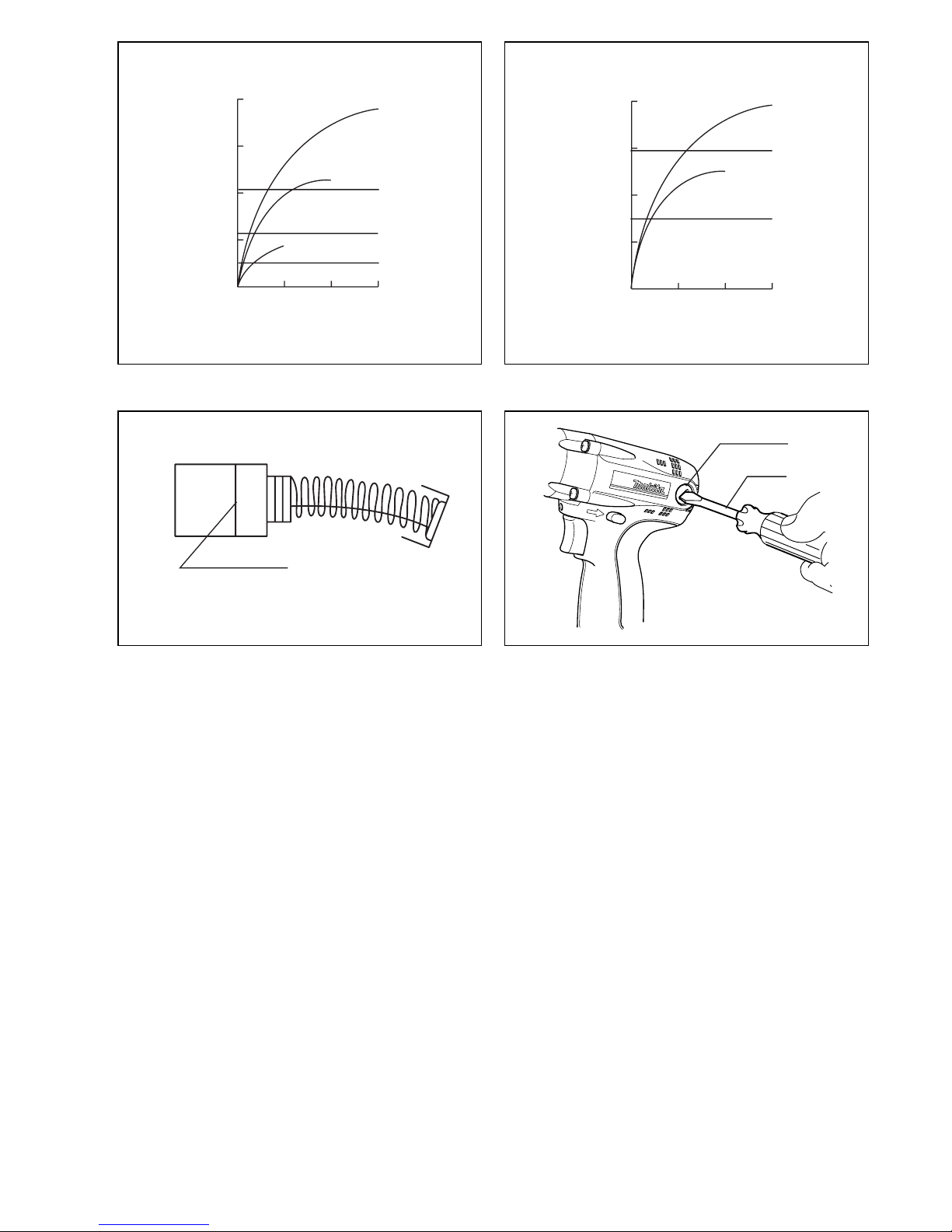
Bediening (Fig. 6 en 7)
Het juiste aandraaikoppel kan verschillen afhankelijk van
het soort en de maat van de schroef/bout, het materiaal
van het te bevestigen werkstuk, enz. De verhouding tus-
sen het aandraaikoppel en de vastdraaitijd is aangege-
ven in Fig.6 voor de standaardbout, en in Fig.7 voor de
bout met hoge trekvastheid.
Houd het gereedschap stevig vast en plaats de punt van
de schroefbit in de schroefkop. Oefen zoveel kracht op
het gereedschap uit als nodig is om de schroefbit op z’n
plaats te houden. Schakel vervolgens het gereedschap
in om de werkzaamheden te starten.
OPMERKING:
• Wanneer u schroef M8 of een schroef van een kleinere
maat aantrekt, dient u de druk op de trekschakelaar
voorzichtig aan te passen om beschadiging van de
schroef te voorkomen.
• Houd het gereedschap altijd haaks.
• Wanneer u de in de figuren aangegeven vastdraaitijden
overschrijdt, kan de schroef doldraaien of de schroef-
kop of de punt van de schroefbit beschadigd worden.
Het verdient daarom aanbeveling eerst een proefje te
nemen voor het vaststellen van de juiste vastdraaitijd.
Het aandraaikoppel wordt beïnvloed door een groot aan-
tal verschillende faktoren, waaronder de volgende.
Kontroleer na het vastdraaien altijd het aandraaikoppel
met een momentsleutel.
1. Wanneer het batterijpak bijna leeg is, neemt het vol-
tage af en vermindert het aandraaikoppel.
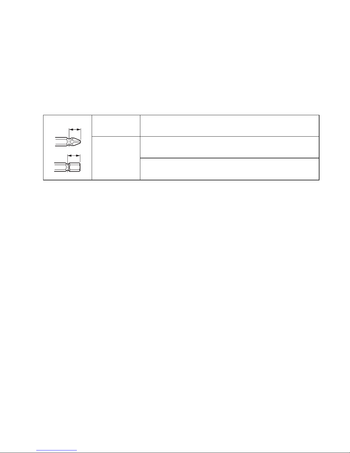
2. Schroefbit of schroefdop
Gebruikt u niet de juiste maat dan heeft een vermin-
dering van de aandraaikoppel plaats.
3. Bout
• In geval het koppelcoefficient overeenkomt met de
boutklasse, hangt het juiste aandraaikoppel af van
de boutdiameter.
• In geval de boutdiameters gelijk zijn, hangt het
juiste aandraaikoppel af van het koppelcoefficient,
de boutklasse en de boutlengte.
4. De manier van vasthouden van het gereedschap en
de positie waarin de schroef in het materiaal vastge-
draaid wordt, beinvloeden het koppel.
5. Bij lagere toerentallen wordt ook het aandraaikoppel
kleiner.
ONDERHOUD
LET OP:
Controleer altijd of de machine is uitgeschakeld en de
accu is losgekoppeld vooraleer onderhoud uit te voeren
aan de machine.
Vervangen van koolborstels (Fig.8en9)
Verwijder en controleer regelmatig de koolborstels. Ver-
vang de koolborstels wanneer ze tot aan de limietmarke-
ring versleten zijn. Houd de koolborstels schoon zodat ze
goed in de houders glijden. Beide koolborstels dienen
tegelijkertijd te worden vervangen. Gebruik uitsluitend
identieke koolborstels.
Gebruik een schroevendraaier om de doppen van de
koolborstelhouders te verwijderen. Haal de versleten bor-
stels eruit, steek de nieuwe erin, en zet de doppen weer
goed vast.
Steek na het vervangen van de koolborstels de accu in
het gereedschap, en laat het gereedschap ongeveer 1
minuut onbelast draaien om de nieuwe koolborstels te
doen wennen. Controleer vervolgens de werking van het
gereedschap en de werking van de elektrische rem bij
het loslaten van de trekschakelaar. Als de elektrische
rem niet goed werkt, moet u deze laten repareren in het
dichtstbijzijnde Makita servicecentrum.
Om de VEILIGHEID en BETROUWBAARHEID van het
product te handhaven, dienen alle reparaties en alle
andere onderhoudswerkzaamheden of afstellingen te
worden uitgevoerd door een erkend Makita Servicecen-
trum, en dat uitsluitend met gebruik van Makita vervan-
gingsonderdelen.
ACCESSOIRES
LET OP:
• Deze accessoires of hulpstukken worden aanbevolen
voor gebruik met het Makita gereedschap dat in deze
gebruiksaanwijzing is beschreven. Bij gebruik van
andere accessoires of hulpstukken bestaat er gevaar
voor persoonlijke verwonding. Gebruik de accessoires
of hulpstukken uitsluitend voor hun bestemde doel.
Raadpleeg het dichtstbijzijnde Makita Servicecentrum
voor verder advies of bijzonderheden omtrent deze
accessoires.
•Schroefbits
• Diverse types originele Makita accu’s en acculaders
• Plastic draagkoffer

41
ENH102-4
EC-DECLARATION OF CONFORMITY
We declare under our sole responsibility that this product
is in compliance with the following standards of standard-
ized documents, EN60745, EN55014
in accordance with Council Directives, 89/336/EEC and
98/37/EC.
DÉCLARATION DE CONFORMITÉ CE
Nous déclarons sous notre entière responsabilité que ce
produit est conforme aux normes des documents stan-
dardisés suivants,EN60745, EN55014
conformément aux Directives du Conseil, 89/336/CEE et
98/37/EG.
CE-KONFORMITÄTSERKLÄRUNG
Hiermit erklärt wir unter unserer alleinigen Verantwor-
tung, daß dieses Produkt gemäß den Ratsdirektiven 89/
336/EWG und 98/37/EG mit den folgenden Normen von
Normendokumenten übereinstimmen:
EN60745, EN55014.
DICHIARAZIONE DI CONFORMITÀ
CON LE NORME DELLA COMUNITÀ EUROPEA
Dichiariamo sotto la nostra sola responsabilità che
questo prodotto è conforme agli standard di documenti
standardizzati seguenti:
EN60745, EN55014
secondo le direttive del Consiglio 89/336/CEE e 98/37/
CE.
EG-VERKLARING VAN CONFORMITEIT
Wij verklaren hierbij uitsluitend op eigen verant-
woordelijkheid dat dit produkt voldoet aan de volgende
normen van genormaliseerde documenten,
EN60745, EN55014
in overeenstemming met de richtlijnen van de Raad 89/
336/EEC en 98/37/EC.
DECLARACIÓN DE CONFORMIDAD DE LA CE
Declaramos bajo nuestra sola responsabilidad que este
producto cumple con las siguientes normas de docu-
mentos normalizados,
EN60745, EN55014
de acuerdo con las directivas comunitarias, 89/336/EEC
y 98/37/CE.
Yasuhiko Kanzaki
CE 2005
Director Amministratore
Directeur Directeur
Direktor Director
MAKITA INTERNATIONAL EUROPE LTD.
Michigan Drive, Tongwell, Milton Keynes,
Bucks MK15 8JD, ENGLAND
Responsible manufacturer: Produttore responsabile:
Fabricant responsable :Verantwoordelijke fabrikant:
Verantwortlicher Hersteller: Fabricante responsable:
Makita Corporation Anjo Aichi Japan
ENGLISH
FRANÇAISE
DEUTSCH
ITALIANO
NEDERLANDS
ESPAÑOL

42
ENH102-4
DECLARAÇÃO DE CONFORMIDADE DA CE
Declaramos sob inteira responsabilidade que este
produto obedece às seguintes normas de documentos
normalizados, EN60745, EN55014
de acordo com as directivas 89/336/CEE e 98/37/CE do
Conselho.
EU-DEKLARATION OM KONFORMITET
Vi erklærer hermed på eget ansvar, at dette produkt er i
overensstemmelse med de følgende standarder i de
normsættende dokumenter,
EN60745, EN55014
i overensstemmelse med Rådets Direktiver 89/336/EEC
og 98/37/EC.
EG-DEKLARATION OM ÖVERENSSTÄMMELSE
Under eget ansvar deklarerar vi härmed att denna
produkt överensstämmer med följande standardiseringar
för standardiserade dokument,
EN60745, EN55014
i enlighet med EG-direktiven 89/336/EEC och 98/37/EC.
EUs SAMSVARS-ERKLÆRING
Vi
erklærer
på
eget ansvar at dette produktet er i over-
ensstemmelse med følgende standard i de standardis-
erte dokumenter: EN60745, EN55014,
i samsvar med Råds-direktivene, 89/336/EEC og 98/37/
EC.
VAKUUTUS EC-VASTAAVUUDESTA
Yksinomaisesti vastuullisina ilmoitamme, että tämä tuote
on seuraavien standardoitujen dokumenttien standardien
mukainen, EN60745, EN55014
neuvoston direktiivien 89/336/EEC ja 98/37/EC mukai-
sesti.
∆ΗΛΩΣΗ ΣΥΜΜΟΡΦΩΣΗΣ ΕΚ
∆ηλώνουµε υπ την µοναδική µας ευθύνη τι αυτ
το προιν βρίσκεται σε Συµφωνία µε τα ακλουθα
πρτυπα τυποποιηµένων εγγράφων,
EN60745, EN55014
σύµφωνα µε τις Οδηγίες του Συµβουλίου, 89/336/
EEC και 98/37/ΚE.
Yasuhiko Kanzaki
CE 2005
Director Direktor
Direktør Johtaja
Direktör ∆ιευθυντής
MAKITA INTERNATIONAL EUROPE LTD.
Michigan Drive, Tongwell, Milton Keynes,
Bucks MK15 8JD, ENGLAND
Fabricante responsável: Ansvarlig produsent:
Ansvarlig fabrikant: Vastaava valmistaja:
Ansvarig tillverkare: Υπεύθυνος κατασκευαστής:
Makita Corporation Anjo Aichi Japan
PORTUGUÊS
DANSK
SVENSKA
NORSK
SUOMI
ΕΛΛΗΝΙΚΑ

43
ENG006-2-V4
For European countries only
Noise and Vibration
The typical A-weighted noise levels are
sound pressure level: 95 dB (A)
sound power level: 106 dB (A)
Uncertainty is 3 dB (A).
– Wear ear protection. –
The typical weighted root mean square acceleration
value is 10 m/s2.
These values have been obtained according to
EN60745.
Pour les pays d’Europe uniquement
Bruit et vibrations
Les niveaux de bruit ponderes types A sont:
niveau de pression sonore: 95 dB (A)
niveau de puissance du son: 106 dB (A)
L’incertitude de mesure est de 3 dB (A).
– Porter des protecteurs anti-bruit. –
L’accélération pondérée est de 10 m/s2.
Ces valeurs ont été obtenues selon EN60745.
Nur für europäische Länder
Geräusch- und Vibrationsentwicklung
Die typischen A-bewerteten Geräuschpegel betragen:
Schalldruckpegel: 95 dB (A)
Schalleistungspegel: 106 dB (A)
Die Abweichung beträgt 3 dB (A).
– Gehörschutz tragen. –
Der gewichtete Effektivwert der Beschleunigung beträgt
10 m/s2.
Diese Werte wurden gemäß EN60745 erhalten.
Modello per l’Europa soltanto
Rumore e vibrazione
I livelli del rumore pesati secondo la curva A sono:
Livello pressione sonora: 95 dB (A)
Livello potenza sonora: 106 dB (A)
L’incertezza è di 3 dB (A).
– Indossare i paraorecchi. –
Il valore quadratico medio di accellerazione è di 10m/s2.
Questi valori sono stati ottenuti in conformità EN60745.
Alleen voor Europese landen
Geluidsniveau en trilling
De typische A-gewogen geluidsniveau’s zijn
geluidsdrukniveau: 95dB (A)
geluidsenergie-niveau: 106dB (A)
Onzekerheid is 3 dB (A).
– Draag oorbeschermers. –
De typische gewogen effectieve versnellingswaarde is
10m/s2.
Deze waarden werden verkregen in overeenstemming
met EN60745.
Para países europeos solamente
Ruido y vibración
Los niveles típicos de ruido ponderados A son
presión sonora: 95dB (A)
nivel de potencia sonora: 106dB (A)
Incerteza 3 dB (A).
– Póngase protectores en los oídos. –
El valor ponderado de la aceleración es de 10m/s2.
Estos valores han sido obtenidos de acuerdo con
EN60745.
ENGLISH
FRANÇAISE
DEUTSCH
ITALIANO
NEDERLANDS
ESPAÑOL

Makita Corporation
Anjo, Aichi, Japan
884511C998
ENG006-2-V4
Só para países Europeus
Ruído e vibração
Os níveis normais de ruído A são
nível de pressão de som: 95 dB (A)
nível do sum: 106 dB (A)
A incerteza é de 3 dB (A).
– Utilize protectores para os ouvidos –
O valor médio da aceleração é 10m/s2.
Estes valores foram obtidos de acordo com EN60745.
Kun for lande i Europa
Lyd og vibration
De typiske A-vægtede lydniveauer er
lydtryksniveau: 95dB (A)
lydeffektniveau: 106dB (A)
Der er en usikkerhed på 3 dB (A).
– Bær høreværn. –
Den vægtede effektive accelerationsværdi er 10m/s2.
Disse værdier er beregnet i overensstemmelse med
EN60745.
Endast för Europa
Buller och vibration
De typiska A-vägda bullernivåerna är
ljudtrycksnivå: 95dB (A)
ljudeffektnivå: 106dB (A)
Osäkerheten är 3 dB (A).
– Använd hörselskydd –
Det typiskt vägda effektivvärdet för acceleration är
10 m/s2.
Dessa värden har erhållits i enlighet med EN60745.
Gjelder bare land i Europa
Støy og vibrasjon
De vanlige A-belastede støynivå er
lydtrykksnivå: 95dB (A)
lydstyrkenivå: 106dB (A)
Usikkerheten er på 3 dB (A).
– Benytt hørselvern. –
Den vanlig belastede effektiv-verdi for akselerasjon er
10m/s2.
Disse verdiene er beregnet eller målt i samsvar med
EN60745.
Vain Euroopan maat
Melutaso ja tärinä
Tyypilliset A-painotetut melutasot ovat
äänenpainetaso: 95dB (A)
äänen tehotaso: 106dB (A)
Epävarmuus on 3 dB (A).
– Käytä kuulosuojaimia. –
Tyypillinen kiihtyvyyden painotettu tehollisarvo on
10m/s2.
Nämä arvot on mitattu normin EN60745 mukaisesti.
Μνο για χώρες της Ευρώπης
Θρυβος και κραδασµς
Οι τυπικές A-µετρούµενες εντάσεις ήχου είναι
πίεση ήχου: 95 dB (A)
δύναµη του ήχου: 106 dB (A)
Η Αβεβαιτητα είναι 3 dB (A).
– Φοράτε ωτοασπίδες. –
Η τυπική αξία της µετρούµενης ρίζας του µέσου
τετραγώνου της επιτάχυνσης είναι 10 m/s2.
Αυτές οι τιµές έχουν σηµειωθεί σύµφωνα µε το
EN60745.
PORTUGUÊS
DANSK
SVENSKA
NORSK
SUOMI
ΕΛΛΗΝΙΚΑ
Other manuals for 6916FD
4
Table of contents
Languages:
Other Makita Impact Driver manuals

Makita
Makita TD003G User manual

Makita
Makita TD111DY1J User manual

Makita
Makita TD0101 User manual

Makita
Makita DTD152 User manual

Makita
Makita TD0101 User manual

Makita
Makita XT328M User manual

Makita
Makita BTL061 Quick start guide

Makita
Makita DTW301 User manual

Makita
Makita BTD200 User manual

Makita
Makita BTD129 User manual

Makita
Makita 6953 User manual

Makita
Makita CT324 User manual

Makita
Makita TW0350 User manual

Makita
Makita TD111DSME User manual

Makita
Makita BTD129 User manual

Makita
Makita 6936FD User manual

Makita
Makita BTW201 Manual

Makita
Makita TD001G User manual

Makita
Makita DTD134 User manual

Makita
Makita BTW120 User manual