Makita DTD137 User manual

1
GB Cordless Impact Driver INSTRUCTION MANUAL
SI Akumulatorski udarni vijačnik NAVODILO ZA UPORABO
AL Vidhosës me goditje me bateri MANUALI I PËRDORIMIT
BG Акумулаторен ударен винтоверт
РЪКОВОДСТВО ЗА ЕКСПЛОАТАЦИЯ
HR Akumulatorski udarni zavrtačPRIRUČNIK S UPUTAMA
MK Безжичен ударен одвртувач
У
ПАТСТВО ЗА УПОТРЕБА
RO
Maşinăde înşurubat cu impact cu acumulator
MANUAL DE INSTRUCŢIUNI
RS Бежични ударни одвртач
У
ПУТСТВО ЗА УПОТРЕБУ
RUS
Аккумуляторный ударный шуруповерт
РУКОВОДСТВО ПО ЭКСПЛУАТАЦИИ
UA
Акумуляторний ударний шурупокрут
ІНСТРУКЦІЯ ЗЕКСПЛУАТАЦІЇ
DTD137
DTD148

2
1
2
3
1 014963
1
2 012128
1
2
3 015659
1
4 014964
1
5 014965
1
6 014966
11
AB
7 014967
1
8 014994 9 004521
12
10 011406
123
11 011407
1
23
12 014969
13 014978

3
ENGLISH (Original instructions)
Explanation of general view
1-1. Red indicator
1-2. Button
1-3. Battery cartridge
2-1. Star marking
3-1. Indicator lamps
3-2. CHECK button
4-1. Switch trigger
5-1. Lamp
6-1. Button
7-1. Reversing switch lever
8-1. Battery capacity
10-1. Bit
10-2. Sleeve
11-1. Bit
11-2. Bit-piece
11-3. Sleeve
12-1. Groove
12-2. Hook
12-3. Screw
SPECIFICATIONS
Model DTD137 DTD148
Machine screw 4 mm - 8 mm 4 mm - 8 mm
Standard bolt 5 mm - 16 mm 5 mm - 16 mm
Capacities
High tensile bolt 5 mm - 14 mm 5 mm - 14 mm
Impact mode (Hard) 0 - 3,400 min-1 0 - 3,600 min-1
Impact mode (Medium) 0 - 2,100 min-1 0 - 2,100 min-1
Impact mode (Soft) 0 - 1,100 min-1 0 - 1,100 min-1
No load speed
T mode 0 - 3,400 min-1 0 - 3,600 min-1
Impact mode (Hard) 0 - 3,600 min-1 0 - 3,800 min-1
Impact mode (Medium) 0 - 2,600 min-1 0 - 2,600 min-1
Impact mode (Soft) 0 - 1,100 min-1 0 - 1,100 min-1
Impacts per minute
T mode 0 - 2,600 min-1 0 - 2,600 min-1
Rated voltage D.C. 14.4 V D.C. 18 V
Overall length 119 mm 119 mm
Battery cartridge BL1415 /
BL1415N
BL1430 / BL1430B /
BL1440 / BL1450 /
BL1460B
BL1815 /
BL1815N /
BL1820 /
BL1820B
BL1830 / BL1830B /
BL1840 / BL1840B /
BL1850 / BL1850B /
BL1860B
Net weight 1.2 kg 1.4 kg 1.2 kg 1.5 kg
• Due to our continuing program of research and development, the specifications herein are subject to change without notice.
• Specifications and battery cartridge may differ from country to country.
• Weight, with battery cartridge, according to EPTA-Procedure 01/2003
ENE033-1
Intended use
The tool is intended for screw driving in wood, metal
and plastic.
ENG905-1
Noise
The typical A-weighted noise level determined
according to EN60745:
Model DTD137
Sound pressure level (LpA) : 95 dB (A)
Sound power level (LWA) : 106 dB (A)
Uncertainty (K) : 3 dB (A)
Model DTD148
Sound pressure level (LpA) : 96 dB (A)
Sound power level (LWA) : 107 dB (A)
Uncertainty (K) : 3 dB (A)
Wear ear protection
ENG900-1
Vibration
The vibration total value (tri-axial vector sum)
determined according to EN60745:
Model DTD137
Work mode : impact tightening of fasteners of the
maximum capacity of the tool
Vibration emission (ah) : 11.0 m/s2
Uncertainty (K) : 1.5 m/s2
Model DTD148
Work mode : impact tightening of fasteners of the
maximum capacity of the tool
Vibration emission (ah) : 12.5 m/s2
Uncertainty (K) : 1.5 m/s2

4
ENG901-1
• The declared vibration emission value has been
measured in accordance with the standard test
method and may be used for comparing one tool
with another.
• The declared vibration emission value may also be
used in a preliminary assessment of exposure.
WARNING:
• The vibration emission during actual use of the
power tool can differ from the declared emission
value depending on the ways in which the tool is
used.
• Be sure to identify safety measures to protect the
operator that are based on an estimation of
exposure in the actual conditions of use (taking
account of all parts of the operating cycle such as
the times when the tool is switched off and when it
is running idle in addition to the trigger time).
ENH101-18
For European countries only
EC Declaration of Conformity
Makita declares that the following Machine(s):
Designation of Machine:
Cordless Impact Driver
Model No./ Type: DTD137, DTD148
Conforms to the following European Directives:
2006/42/EC
They are manufactured in accordance with the following
standard or standardized documents:
EN60745
The technical file in accordance with 2006/42/EC is
available from:
Makita, Jan-Baptist Vinkstraat 2, 3070, Belgium
20.1.2014
000331
Yasushi Fukaya
Director
Makita, Jan-Baptist Vinkstraat 2, 3070, Belgium
GEA010-1
General Power Tool Safety
Warnings
WARNING Read all safety warnings and all
instructions. Failure to follow the warnings and
instructions may result in electric shock, fire and/or
serious injury.
Save all warnings and instructions for
future reference.
GEB054-3
CORDLESS IMPACT DRIVER
SAFETY WARNINGS
1. Hold power tool by insulated gripping
surfaces, when performing an operation
where the fastener may contact hidden wiring.
Fasteners contacting a "live" wire may make
exposed metal parts of the power tool "live" and
could give the operator an electric shock.
2. Always be sure you have a firm footing.
Be sure no one is below when using the tool
in high locations.
3. Hold the tool firmly.
4. Wear ear protectors.
5. Do not touch the bit or the workpiece
immediately after operation. They may be
extremely hot and could burn your skin.
6. Keep hands away from rotating parts.
SAVE THESE INSTRUCTIONS.
WARNING:
DO NOT let comfort or familiarity with product
(gained from repeated use) replace strict adherence
to safety rules for the subject product.
MISUSE or failure to follow the safety rules stated in
this instruction manual may cause serious personal
injury.
ENC007-9
IMPORTANT SAFETY
INSTRUCTIONS
FOR BATTERY CARTRIDGE
1. Before using battery cartridge, read all
instructions and cautionary markings on (1)
battery charger, (2) battery, and (3) product
using battery.
2. Do not disassemble battery cartridge.
3. If operating time has become excessively
shorter, stop operating immediately. It may
result in a risk of overheating, possible burns
and even an explosion.
4. If electrolyte gets into your eyes, rinse them
out with clear water and seek medical
attention right away. It may result in loss of
your eyesight.
5. Do not short the battery cartridge:
(1) Do not touch the terminals with any
conductive material.
(2) Avoid storing battery cartridge in a
container with other metal objects such
as nails, coins, etc.
(3) Do not expose battery cartridge to water
or rain.

5
A battery short can cause a large current flow,
overheating, possible burns and even a
breakdown.
6. Do not store the tool and battery cartridge in
locations where the temperature may reach or
exceed 50 ゚C (122 ゚F).
7. Do not incinerate the battery cartridge even if
it is severely damaged or is completely worn
out. The battery cartridge can explode in a fire.
8. Be careful not to drop or strike battery.
9. Do not use a damaged battery.
10. Follow your local regulations relating to
disposal of battery.
SAVE THESE INSTRUCTIONS.
Tips for maintaining maximum battery life
1. Charge the battery cartridge before
completely discharged.
Always stop tool operation and charge the
battery cartridge when you notice less tool
power.
2. Never recharge a fully charged battery
cartridge.
Overcharging shortens the battery service life.
3. Charge the battery cartridge with room
temperature at 10 ゚C - 40 ゚C (50 ゚F - 104 ゚F).
Let a hot battery cartridge cool down before
charging it.
4. Charge the battery cartridge if you do not use
it for a long period (more than six months).
FUNCTIONAL DESCRIPTION
CAUTION:
• Always be sure that the tool is switched off and the
battery cartridge is removed before adjusting or
checking function on the tool.
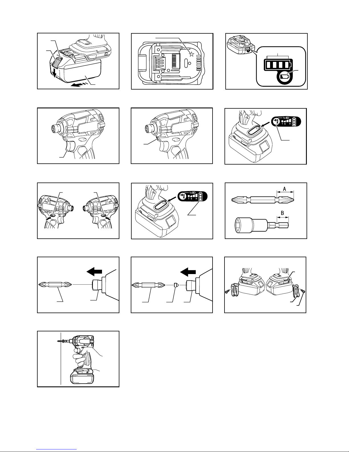
Installing or removing battery cartridge
Fig.1
CAUTION:
• Always switch off the tool before installing or
removing of the battery cartridge.
•
Hold the tool and the battery cartridge firmly when
installing or removing battery cartridge.
Failure to
hold the tool and the battery cartridge firmly may cause
them to slip off your hands and result in damage to the
tool and battery cartridge and a personal injury.
To remove the battery cartridge, slide it from the tool
while sliding the button on the front of the cartridge.
To install the battery cartridge, align the tongue on the
battery cartridge with the groove in the housing and slip
it into place. Insert it all the way until it locks in place
with a little click. If you can see the red indicator on the
upper side of the button, it is not locked completely.
CAUTION:
• Always install the battery cartridge fully until the
red indicator cannot be seen. If not, it may
accidentally fall out of the tool, causing injury to
you or someone around you.
• Do not install the battery cartridge forcibly. If the
cartridge does not slide in easily, it is not being
inserted correctly.
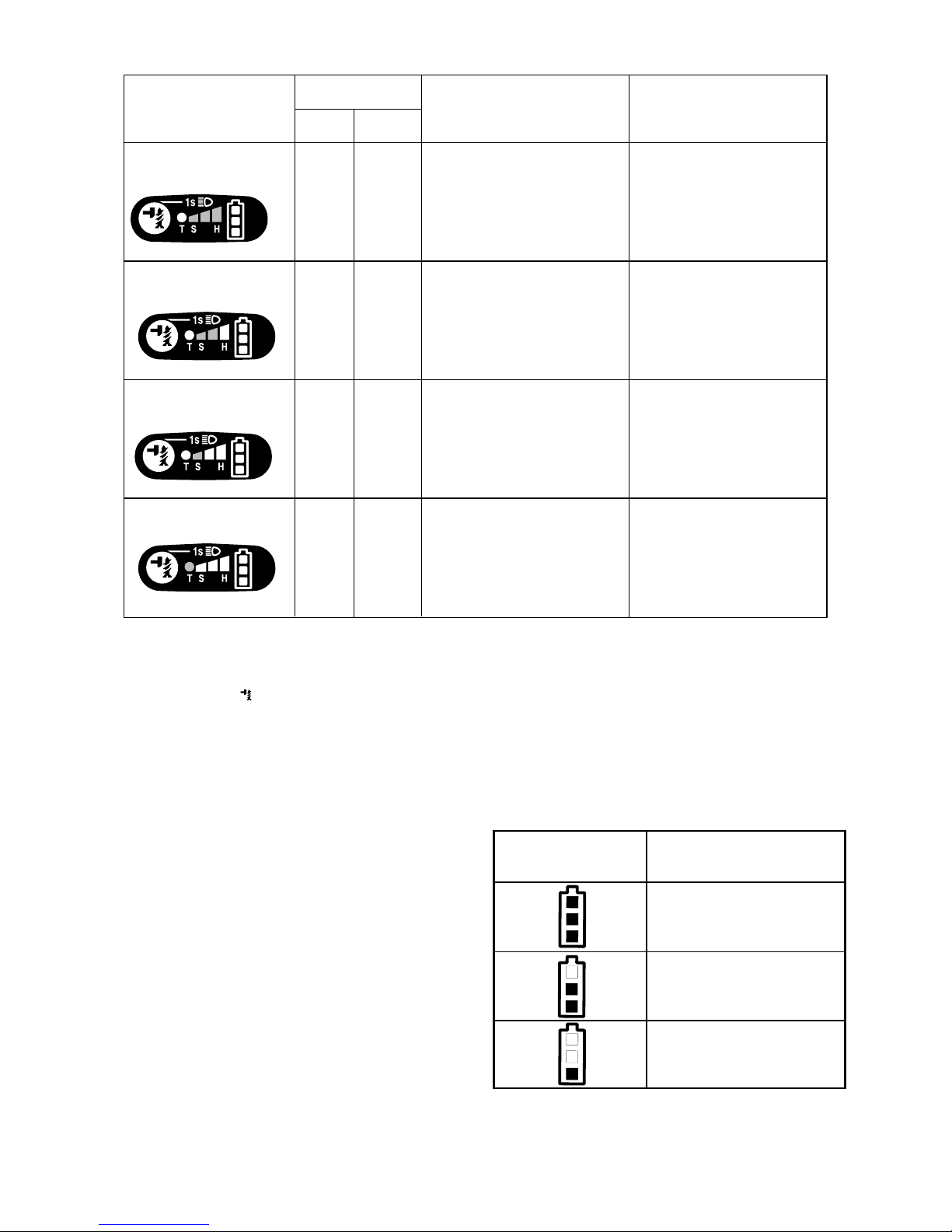
Battery protection system
(Lithium-ion battery with star marking)
Fig.2
Lithium-ion batteries with a star marking are equipped
with a protection system. This system automatically cuts
off power to the tool to extend battery life.
The tool will automatically stop during operation if the
tool and/or battery are placed under one of the following
conditions:
• Overloaded:
The tool is operated in a manner that causes
it to draw an abnormally high current.
In this situation, release the switch trigger on
the tool and stop the application that caused
the tool to become overloaded. Then pull the
switch trigger again to restart.
If the tool does not start, the battery is
overheated. In this situation, let the battery
cool before pulling the switch trigger again.
• Low battery voltage:
The remaining battery capacity is too low
and the tool will not operate. In this situation,
remove and recharge the battery.

6
Indicating the remaining battery capacity
(Only for battery cartridges with "B" at the end of the
model number.)
Fig.3
Press the check button on the battery cartridge to
indicate the remaining battery capacity. The indicator
lamps light up for few seconds.
Off BlinkingLighted
Indicator lamps
Charge the
battery.
0% to 25%
25% to 50%
50% to 75%
75% to 100%
Remaining
capacity
The battery
may have
malfunctioned.
015658
NOTE:
• Depending on the conditions of use and the
ambient temperature, the indication may differ
slightly from the actual capacity.
Switch action
Fig.4
CAUTION:
•
Before inserting the battery cartridge into the tool, always
check to see that the switch trigger actuates properly
and returns to the "OFF" position when released.
To start the tool, simply pull the switch trigger. Tool
speed is increased by increasing pressure on the switch
trigger. Release the switch trigger to stop.
NOTE:
• The tool automatically stops if you keep pulling the
switch trigger for about 180 seconds.
Lighting up the front lamp
CAUTION:
•
Do not look in the light or see the source of light directly.
Fig.5
Fig.6
To turn on the lamp status, press the button for few
seconds. To turn off the lamp status, press the button
for few seconds again.
With the lamp status ON, pull the switch trigger to turn on the
lamp. To turn off, release it. The lamp goes out approximately
10 seconds after releasing the switch trigger.
With the lamp status OFF, the lamp will not turn on even
if the trigger is pulled.
NOTE:
• To confirm the lamp status, pull the trigger. When
the lamp lights up by pulling the switch trigger, the
lamp status is ON. When the lamp does not come
on, the lamp status is OFF.
• While pulling the switch trigger, the lamp status
cannot be changed.
• For approximately 10 seconds after releasing the
switch trigger, the lamp status can be changed.
Reversing switch action
Fig.7
This tool has a reversing switch to change the direction
of rotation. Depress the reversing switch lever from the
A side for clockwise rotation or from the B side for
counterclockwise rotation.
When the reversing switch lever is in the neutral
position, the switch trigger cannot be pulled.
CAUTION:
•
Always check the direction of rotation before operation.
• Use the reversing switch only after the tool comes
to a complete stop. Changing the direction of
rotation before the tool stops may damage the tool.
• When not operating the tool, always set the
reversing switch lever to the neutral position.
Changing the impact force
1
2
3
4
5
6
012609
1. Changed in four steps
2. Hard
3. Medium
4. Soft
5. T mode
6. Button

7
Impact force grade
displayed on panel
Maximum blows
Application Work
Hard
Medium
Soft
Tightening when force
and speed are desired.
Tightening when agood
finishing isneeded.
Tightening when excessive
tightening need to be avoided
because of potentiallyclogged
femalescrew and broken or
damaged screw head.
Tightening inunderwork
material/ Tightening long
screws/ Tightening bolts.
Tightening inthe finishing
board, plaster board.
Tightening sash screw/
Tightening small screws
such as M6.
3,600
(min-1)
DTD137DTD148
3,800
(min-1)
2,600
(min-1)
2,600
(min-1)
1,100
(min-1)
1,100
(min-1)
T mode
2,600
(min-1)
2,600
(min-1)
Tightening when speed
and good finishing are needed.
Tightening self
drilling screws.
014968
The impact force can be changed in four steps: hard,
medium, soft, and T mode.
This allows a tightening suitable to the work.
Every time the button is pressed, the number of blows
changes in four steps.
"T" is a special mode for fastening self drilling screws. In
this mode, the tool starts to drive a screw with faster
rotation, which is suited for drilling with the self-drilling -
screw tip. Once the tool starts to tighten the screw, it
impacts in medium force grade.
For approximately one minute after releasing the switch
trigger, the impact force can be changed.
NOTE:
• When all lamps on the switch panel go out, the
tool is turned off to save the battery power. The
impact force grade can be checked by pulling the
switch trigger to the extent that the tool does not
operate.
• While pulling the switch trigger, the impact force
grade cannot be changed.
Indicating the remaining battery
capacity
(Country specific)
Fig.8
When you pull the switch trigger, the LED display shows
the remaining battery capacity.
The remaining battery capacity is shown as the
following table.
LED indicator status Remaining battery capacity
About 50% or more
About 20% - 50%
About less than 20%
012273

8
NOTE:
• When the LED display goes off, the tool is turned
off to save the battery power. To check the
remaining battery capacity, slightly pull the switch
trigger.
• The LED display goes off approximately one
minute after releasing the switch trigger.
• When the tool is overheated, the light blinks for
one minute, and then the LED display goes off. In
this case, cool down the tool before operating
again.
• When the LED display lights up and the tool stops
even with a recharged battery cartridge, cool down
the tool fully. If the status will not change, stop
using and have the tool repaired by a Makita local
service center.
ASSEMBLY
CAUTION:
• Always be sure that the tool is switched off and the
battery cartridge is removed before carrying out
any work on the tool.
Installing or removing driver bit or socket bit
Fig.9
Use only bits that has inserting portion shown in the
figure.
For tool with shallow bit hole
A=12mm
B=9mm
Use only these type of bit. Followthe
procedure (1).
(Note)Bit-piece is not necessary.
006348
For tool with deep bit hole
To install these types of bits,follow
the procedure (1).
To install these types of bits,follow
the procedure (2).
(Note)Bit-piece is necessary for
installing the bit.
A=17mm
B=14mm
A=12mm
B=9mm
011405
Procedure 1
For tool with normal sleeve
Fig.10
To install the bit, pull the sleeve in the direction of the
arrow and insert the bit into the sleeve as far as it will go.
Then release the sleeve to secure the bit.
For tool with one-touch type sleeve
To install the bit, insert the bit into the sleeve as far as it
will go.
Procedure 2
In addition to the procedure(1) above, insert the bit-
piece into the sleeve with its pointed end facing in.
Fig.11
To remove the bit, pull the sleeve in the direction of the
arrow and pull the bit out.
NOTE:
• If the bit is not inserted deep enough into the
sleeve, the sleeve will not return to its original
position and the bit will not be secured. In this
case, try re-inserting the bit according to the
instructions above.
• When it is difficult to insert the bit, pull the sleeve
and insert it into the sleeve as far as it will go.
• After inserting the bit, make sure that it is firmly
secured. If it comes out, do not use it.
Hook
Fig.12
The hook is convenient for temporarily hanging the tool.
This can be installed on either side of the tool.
To install the hook, insert it into a groove in the tool
housing on either side and then secure it with a screw.
To remove, loosen the screw and then take it out.
OPERATION
Fig.13
The proper fastening torque may differ depending upon
the kind or size of the screw/bolt, the material of the
workpiece to be fastened, etc. The relation between
fastening torque and fastening time is shown in the
figures.
Model DTD137
140
(1,428)
120
100
80
60
40
20
01.02.03.0
M14
M12
M10
M8
M16
M14
M12
M10
M8
Standard bolt
N m
Fastening torque
Fastening time (S)
Proper fastening torque
(kgf cm)
(1,224)
(1,020)
(816)
(612)
(408)
(204)
M16
014970

9
200
(2,040)
180
(1,836)
160
(1,632)
140
(1,428)
120
(1,224)
100
(1,020)
80
(816)
60
(612)
40
(408)
20
(204)
01.02.03.0
M14
M12
M14
M12
M10
M8
M10
M8
High tensilebolt
N m
Fastening torque
Fastening time (S)
Proper fastening torque
(kgf cm)
014971
Model DTD148
140
(1,428)
120
100
80
60
40
20
01.02.0
M14
M12
M10
M8
M16
M14
M12
M10
M8
Standard bolt
N m
Fastening torque
Fastening time (S)
Proper fastening torque
(kgf cm)
(1,224)
(1,020)
(816)
(612)
(408)
(204)
M16
014972
200
(2,040)
180
(1,836)
160
(1,632)
140
(1,428)
120
(1,224)
100
(1,020)
80
(816)
60
(612)
40
(408)
20
(204)
01.02.03.0
M14
M12
M14
M12
M10
M8
M10
M8
High tensilebolt
N m
Fastening torque
Fastening time (S)
Proper fastening torque
(kgf cm)
014973
Hold the tool firmly and place the point of the driver bit
in the screw head. Apply forward pressure to the tool to
the extent that the bit will not slip off the screw and turn
the tool on to start operation.
NOTE:
• Use the proper bit for the head of the screw/bolt
that you wish to use.
• When fastening M8 or smaller screw, choose a
proper impact force and carefully adjust pressure
on the switch trigger so that the screw is not
damaged.
• Hold the tool pointed straight at the screw.
• If the impact force is too strong you tighten the
screw for a time longer than shown in the figures,
the screw or the point of the driver bit may be
overstressed, stripped, damaged, etc. Before
starting your job, always perform a test operation
to determine the proper fastening time for your
screw.
The fastening torque is affected by a wide variety of
factors including the following. After fastening, always
check the torque with a torque wrench.
1. When the battery cartridge is discharged almost
completely, voltage will drop and the fastening
torque will be reduced.
2. Driver bit or socket bit
Failure to use the correct size driver bit or socket
bit will cause a reduction in the fastening torque.
3. Bolt
• Even though the torque coefficient and the
class of bolt are the same, the proper
fastening torque will differ according to the
diameter of bolt.
• Even though the diameters of bolts are the
same, the proper fastening torque will differ
according to the torque coefficient, the class
of bolt and the bolt length.
4. The manner of holding the tool or the material of
driving position to be fastened will affect the
torque.
5. Operating the tool at low speed will cause a
reduction in the fastening torque.
MAINTENANCE
CAUTION:
• Always be sure that the tool is switched off and the
battery cartridge is removed before attempting to
perform inspection or maintenance except for the
following troubleshooting related to the light.
• Never use gasoline, benzine, thinner, alcohol or
the like. Discoloration, deformation or cracks may
result.
To maintain product SAFETY and RELIABILITY, repairs,
any other maintenance or adjustment should be
performed by Makita Authorized Service Centers,
always using Makita replacement parts.

10
OPTIONAL ACCESSORIES
CAUTION:
• These accessories or attachments are
recommended for use with your Makita tool
specified in this manual. The use of any other
accessories or attachments might present a risk of
injury to persons. Only use accessory or
attachment for its stated purpose.
If you need any assistance for more details regarding
these accessories, ask your local Makita Service Center.
• Screw bits
• Socket bits
• Hook
• Plastic carrying case
• Makita genuine battery and charger
• Bit-piece
• Battery protector
• Tool hanger
NOTE:
• Some items in the list may be included in the tool
package as standard accessories. They may differ
from country to country.

11
SLOVENŠČINA (izvirna navodila)
Razlaga splošnega pogleda
1-1. Rdeči indikator
1-2. Gumb
1-3. Baterijski vložek
2-1. Oznaka z zvezdico
3-1. Indikatorske lučke
3-2. Gumb CHECK
4-1. Sprožilno stikalo
5-1. Svetilka
6-1. Gumb
7-1. Preklopna ročica za obratno smer
8-1. Zmogljivost akumulatorja
10-1. Nastavek
10-2. Vložek
11-1. Nastavek
11-2. Izenačevalna konica
11-3. Vložek
12-1. Utor
12-2. Kljuka
12-3. Vijak
TEHNIČNI PODATKI
Model DTD137 DTD148
Strojni vijak 4 mm - 8 mm 4 mm - 8 mm
Standardni vijak 5 mm - 16 mm 5 mm - 16 mm
Zmogljivosti
Visokonatezni vijak 5 mm - 14 mm 5 mm - 14 mm
Udarni način (močno) 0 - 3.400 min-1 0 - 3.600 min-1
Udarni način (srednje) 0 - 2.100 min-1 0 - 2.100 min-1
Udarni način (rahlo) 0 - 1.100 min-1 0 - 1.100 min-1
Hitrost brez
obremenitve
Način T 0 - 3.400 min-1 0 - 3.600 min-1
Udarni način (močno) 0 - 3.600 min-1 0 - 3.800 min-1
Udarni način (srednje) 0 - 2.600 min-1 0 - 2.600 min-1
Udarni način (rahlo) 0 - 1.100 min-1 0 - 1.100 min-1
Udarci na minuto
Način T 0 - 2.600 min-1 0 - 2.600 min-1
Nazivna napetost D.C. 14,4 V D.C. 18 V
Skupna dolžina 119 mm 119 mm
Baterijski vložek BL1415 /
BL1415N
BL1430 / BL1430B /
BL1440 / BL1450 /
BL1460B
BL1815 /
BL1815N /
BL1820 /
BL1820B
BL1830 / BL1830B /
BL1840 / BL1840B /
BL1850 / BL1850B /
BL1860B
Neto teža 1,2 kg 1,4 kg 1,2 kg 1,5 kg
• Zaradi našega nenehnega programa raziskav in razvoja si pridržujemo pravico do spremembe tehničnih podatkov brez obvestila.
• Tehnični podatki in baterijski vložki se lahko razlikujejo od države do države.
• Teža z baterijskim vložkom je v skladu z EPTA-postopkom 01/2003
ENE033-1
Namen uporabe
Orodje je namenjeno za vijačenje v les, kovino in plastiko.
ENG905-1
Hrup
Tipični, z A ocenjeni vrednosti hrupa glede na EN60745:
Model DTD137
Raven zvočnega tlaka (LpA): 95 dB (A)
Raven zvočne moči (LWA): 106 dB (A)
Odstopanje (K): 3 dB (A)
Model DTD148
Raven zvočnega tlaka (LpA): 96 dB (A)
Raven zvočne moči (LWA): 107 dB (A)
Odstopanje (K): 3 dB (A)
Uporabljajte zaščito za sluh
ENG900-1
Vibracije
Skupne vrednosti vibracij (vektorska vsota treh osi) po
EN60745:
Model DTD137
Delovni način : udarno privijanje pritrjevalnikov z
največjo zmogljivostjo orodja
Oddajanje tresljajev (ah): 11,0 m/s2
Odstopanje (K): 1,5 m/s2
Model DTD148
Delovni način : udarno privijanje pritrjevalnikov z
največjo zmogljivostjo orodja
Oddajanje tresljajev (ah): 12,5 m/s2
Odstopanje (K): 1,5 m/s2

12
ENG901-1
• Navedena vrednost oddajanja vibracij je bila
izmerjena v skladu s standardnimi metodami
testiranja in se lahko uporablja za primerjavo
orodij.
• Navedena vrednost oddajanja vibracij se lahko
uporablja tudi pri predhodni oceni izpostavljenosti.
OPOZORILO:
• Oddajanje vibracij med dejansko uporabo
električnega orodja se lahko razlikuje od navedene
vrednosti oddajanja, odvisno od načina uporabe
orodja.
• Upravljavec mora za lastno zaščito poznati
varnostne ukrepe, ki temeljijo na oceni
izpostavljenosti v dejanskih pogojih uporabe
(upoštevajočceloten delovni proces v trenutkih, ko
je orodje izključeno in ko deluje v prostem teku z
dodatkom časa sprožitve).
ENH101-18
Samo za evropske države
ES Izjava o skladnosti
Družba Makita izjavlja, da je/so naslednji stroj/-i:
Oznaka stroja:
Akumulatorski udarni vijačnik
Model št./vrsta: DTD137, DTD148
Je skladen z naslednjimi evropskimi direktivami:
2006/42/ES
Izdelan v skladu z naslednjim standardom ali
standardiziranimi dokumenti:
EN60745
Tehnična dokumentacija v skladu z direktivo
2006/42/ES je na voljo na:
Makita, Jan-Baptist Vinkstraat 2, 3070, Belgija
20.1.2014
000331
Yasushi Fukaya
Direktor
Makita, Jan-Baptist Vinkstraat 2, 3070, Belgija
GEA010-1
Splošna varnostna opozorila za
električno orodje
OPOZORILO Preberite vsa varnostna opozorila
in navodila. Neupoštevanje opozoril in navodil lahko
vodi do električnega udara, požara, in/ali hudih telesnih
poškodb.
Shranite vsa opozorila in navodila za
kasnejšo uporabo.
GEB054-3
VARNOSTNA OPOZORILA ZA
BREZŽIČNI UDARNI VIJAČNIK
1. Če obstaja nevarnost, da bi s pritrjevalnikom
prerezali skrito električno napeljavo, držite
električno orodje na izoliranih držalnih
površinah. Ob stiku z vodniki pod napetostjo
dobijo napetost vsi neizolirani kovinski deli
električnega orodja, zaradi česar lahko pride do
električnega udara.
2. Vedno zagotovite, da imate trden oprijem na
podlagi, kjer stojite.
Kadar uporabljate orodje na višini, se
prepričajte, da spodaj ni nikogar.
3. Trdno držite orodje.
4. Uporabljajte zaščito za sluh.
5. Takoj po končani obdelavi se ne dotikajte
nastavka ali obdelovanca. Lahko sta zelo
vroča in povzročita opekline kože.
6. Ne približujte rok vrtečim se delom.
SHRANITE TA NAVODILA.
OPOZORILO:
NE dopustite si, da bi zaradi udobnejšega dela ali
poznavanja izdelka (pridobljenega z večkratno
uporabo) opustili strogo upoštevanje varnostnih
pravil pri pravilni uporabi stroja.
ZLORABA ali neupoštevanje varnostnih pravil v teh
navodilih za uporabo lahko povzroči hude telesne
poškodbe.
ENC007-9
POMEMBNA VARNOSTNA
NAVODILA
ZA BATERIJSKE VLOŽKE
1. Pred uporabo baterijskega vložka preberite
vsa navodila in opozorilne oznake na (1)
polnilniku akumulatorja, (2) akumulatorju in
(3) izdelku, ki uporablja akumulator.
2. Ne razstavljajte baterijskega vložka.
3. Če se je čas delovanja občutno skrajšal, takoj
prekinite z uporabo. V nasprotnem primeru je
lahko rezultat pregretje, morebitne opekline in
celo eksplozija.
4. Če pride elektrolit v oči, jih sperite s čisto
vodo in takoj poiščite zdravniško pomoč.
Posledica je lahko izguba vida.
5. Ne povzročite kratkega stika baterijskega
vložka:
(1) Ne dotikajte se priključkov s kakršnim
koli prevodnim materialom.
(2) Izogibajte se shranjevanju baterijskega
vložka v posodo z drugimi kovinskimi
predmeti kot so žeblji, kovanci itn.

13
(3) Ne izpostavljajte baterijskega vložka vodi
ali dežju.
Kratek stik akumulatorja lahko povzroči velik
tok, pregretje, morebitne opekline in celo
eksplozijo.
6. Ne shranjujte orodja in baterijskega vložka na
lokacijah, kjer lahko temperatura doseže ali
preseže 50 ゚C (122 ゚F).
7. Ne sežigajte baterijskega vložka, tudi če je
hudo poškodovan ali v celoti izpraznjen.
Baterijski vložek lahko v ognju eksplodira.
8. Bodite previdni, da vam akumulator ne pade
in ga ne udarjajte.
9. Ne uporabljajte poškodovanih akumulatorjev.
10. Upoštevajte lokalne uredbe glede odlaganja
akumulatorja.
SHRANITE TA NAVODILA.
Nasveti za maksimalno življenjsko dobo
akumulatorja
1. Napolnite baterijski vložek preden se v celoti
izprazni.
Ko opazite, da ima orodje manjšo moč, vedno
ustavite delovanje orodja in napolnite
baterijski vložek.
2. Nikoli znova ne polnite popolnoma
napolnjenega baterijskega vložka.
Prenapolnjenje skrajša življenjsko dobo
akumulatorja.
3. Napolnite baterijski vložek pri sobni
temperaturi med 10 ゚C in 40 ゚C (50 ゚F - 104 ゚
F). Počakajte, da se vročbaterijski vložek
pred polnjenjem ohladi.
4. Akumulatorsko baterijo napolnite, če je ne
uporabljate dalj časa (dlje kot šest mesecev).
OPIS DELOVANJA
POZOR:
• Pred vsako nastavitvijo ali pregledom delovanja
orodja se prepričajte, da je le to izključeno in da je
akumulatorska baterija odstranjena.
Nameščanje ali odstranjevanje
akumulatorske baterije
Sl.1
POZOR:
• Vedno izklopite orodje, preden namestite ali
odstranite akumulatorsko baterijo.
• Kadar nameščate ali odstranjujete
akumulatorsko baterijo, trdno držite orodje in
akumulatorsko baterijo. Če orodja in
akumulatorske baterije ne držite trdno, se lahko
zgodi, da vam zdrsneta iz rok, posledica pa je
poškodba orodja in akumulatorske baterije ter
telesna poškodba.
Za odstranitev akumulatorske baterije iz orodja jo
premaknite iz orodja, ob tem pa premaknite gumb na
sprednji strani akumulatorske baterije.
Pri vstavljanju akumulatorske baterije poravnajte jeziček
na akumulatorski bateriji z utorom na ohišju in ga
potisnite v ležišče. Akumulatorsko baterijo vstavite do
konca, da se razločno zaskoči. Če vidite rdeči indikator
na zgornji strani gumba, ta ni popolnoma zaklenjen.
POZOR:
• Vedno namestite akumulatorsko baterijo, tako da
rdeči indikator ni večviden. Če tega ne upoštevate,
lahko akumulator nepričakovano izpade iz orodja
in poškoduje vas ali osebe v neposredni bližini.
• Ne nameščajte akumulatorske baterije s silo. Če
se akumulatorska baterija ne zaskoči zlahka, ni
pravilno vstavljena.
Sistem za zaščito akumulatorja
(litij-ionske akumulatorji z zvezdico)
Sl.2
Litij-ionske akumulatorji so opremljene z zaščitnim
sistemom. Ta sistem samodejno izklopi dovajanje
električne energije v orodje, da bi podaljšal življenjsko
dobo baterije.
Orodje se bo samodejno zaustavilo med delovanjem, če
sta orodje in/ali baterija zamenjana pod naslednjimi
pogoji:
• Preobremenjeno:
Orodje deluje na način, ki povzroča, da
povleče nenormalno visok tok.
V takem primeru sprostite sprožilno stikalo
na orodju in ga prenehajte uporabljati na
način, zaradi katerega je prišlo do
preobremenitve. Nato znova povlecite
sprožilno stikalo, da ga zaženete.

14
Če se orodje ne zažene, je akumulator
pregret. V tem primeru pustite, da se
akumulator ohladi, preden znova pritisnete
sprožilno stikalo.
• Nizka napetost akumulatorja:
Preostala zmogljivost akumulatorja je
prenizka in orodje ne bo delovalo. V tem
primeru odstranite in napolnite akumulator.
Prikazuje preostalo zmogljivost akumulatorja
(Samo za akumulatorske baterije z oznako »B« na
koncu številke modela.)
Sl.3
Pritisnite gumb za preverjanje napolnjenosti na
akumulatorski bateriji, da preverite preostalo zmogljivost.
Indikatorske lučke zasvetijo za nekaj sekund.
Ne sveti UtripaSveti
Indikatorske lučke
Napolnite
akumulator.
od 0 % do 25 %
od 25 % do 50 %
od 50 % do 75 %
od 75 % do 100 %
Preostala
zmogljivost
Akumulator
je morda
okvarjen.
015658
OPOMBA:
• Odvisno od pogojev uporabe in okoljske
temperature se označba lahko nekoliko razlikuje
od dejanske napolnjenosti.
Delovanje stikala
Sl.4
POZOR:
• Preden vstavite akumulatorsko baterijo v orodje se
vedno prepričajte, da je stikalo brezhibno in da se
vrača v položaj za izklop (OFF), ko ga spustite.
Za zagon orodja povlecite sprožilno stikalo. Hitrost
orodja se poveča za povečani tlak na sprožilnem stikalu.
Za izklop orodja spustite sprožilno stikalo.
OPOMBA:
• Orodje se samodejno ustavi, če vlečete sprožilno
stikalo približno 180 sekund.
Vklop sprednje lučke
POZOR:
• Ne glejte neposredno v lučko ali vir svetlobe.
Sl.5
Sl.6
Za vklop stanja lučke pritisnite gumb za nekaj
sekund. Za izklop stanja lučke znova pritisnite gumb
za nekaj sekund.
Ko je stanje lučke VKLOPLJENA, povlecite sprožilno
stikalo za vklop lučke. Za izklop pa ga spustite. Lučka
ugasne približno 10 sekund zatem, ko spustite sprožilno
stikalo.
Ko je stanje lučke IZKLOPLJENA, se lučka ne prižge,
tudi če povlečete sprožilnik.
OPOMBA:
• Za potrdite stanja lučke povlecite sprožilnik. Če se
lučka prižge, ko povlečete sprožilno stikalo, je
stanje lučke VKLOPLJENA. Če se lučka ne prižge,
potem je stanje lučke IZKLOPLJENA.
• Med vlečenjem sprožilnega stikala ni mogoče
spreminjati stanja lučke.
• Približno 10 sekund zatem, ko spustite sprožilno
stikalo, lahko spremenite stanje lučke.
Stikalo za preklop smeri vrtenja
Sl.7
To orodje je opremljeno s preklopnikom za spremembo
smeri vrtenja. Ročico preklopnika smeri vrtenja pritisnite
v smeri A za vrtenje v smeri urinega kazalca in v smeri
B za vrtenje v obratni smeri urinega kazalca.
Ko je preklopno stikalo v nevtralnem položaju, se
glavnega stikala ne da premakniti.
POZOR:
• Pred obratovanjem vedno preverite smer vrtenja.
• Stikalo za spreminjanje smeri vrtenja uporabite
šele, ko se stroj popolnoma ustavi. Če smer
vrtenja spremenite, preden se stroj ustavi, se ta
lahko poškoduje.
• Ko orodja ne uporabljate, vedno potisnite
preklopno stikalo v nevtralen položaj.

15
Sprememba udarne sile
1
2
3
4
5
6
012609
Stopnja udarne sile, prikazana
na zaslonu
Največ udarcev Aplikacija Delo
Trdo
Srednja
Mehko
Privijanje, kadar sta potrebna
moč in hitrost.
Privijanje, kadar je potreben
dober zaključek.
Privijanje, kadar se je treba
izogibati čezmernemu privijanju
zaradi morebiti zamašenega
ženskega dela vijaka in zlomljene
ali poškodovane glave vijaka.
Privijanje v material
podzidja/Privijanje dolgih
vijakov/Privijanje matičnih
vijakov.
Privijanje v zaključne plošče,
plošče iz mavca.
Privijanje vijakov za okenske
okvirje/Privijanje majhnih
vijakov, npr. M6.
3.600
(min-1)
DTD137 DTD148
3.800
(min-1)
2.600
(min-1)
2.600
(min-1)
1.100
(min-1)
1.100
(min-1)
Način T
2.600
(min-1)
2.600
(min-1)Privijanje, kadar sta potrebna
hitrost in dober zaključek.
Privijanje samoreznih vijakov.
014968
1. Spremenjeno v štirih korakih
2. Trdo
3. Srednja
4. Mehko
5. Način T
6. Gumb

16
Udarno silo lahko spreminjate v štirih korakih: močno,
srednje, rahlo in način T.
To omogoča privijanje, ki je primerno za delo.
Vsakič, ko pritisnete gumb , se število udarcev
spremeni v štirih korakih.
„T“ je poseben način za privijanje samoreznih vijakov. V
tem načinu orodje začne hitreje privijati vijak, kar je
primerno za vijake s samoreznimi konicami. Ko začne
orodje privijati vijak, je sila srednje močna.
Približno eno minuto zatem, ko spustite sprožilno stikalo,
lahko spremenite udarno silo.
OPOMBA:
• Ko vse lučke na stikalni plošči ugasnejo, se orodje
izključi, da varčuje z akumulatorjem. Stopnjo
udarne sile lahko preverite, tako da povlečete
sprožilno stikalo do te mere, da orodje neha
delovati.
• Med vlečenjem sprožilnega stikala ni mogoče
spreminjati stopnje udarne sile.
Prikazuje preostalo zmogljivost
akumulatorja
(Odvisno od države)
Sl.8
Ko povlečete sprožilno stikalo, se na LED zaslonu
prikaže preostala zmogljivost akumulatorja.
Preostala zmogljivost akumulatorja je prikazana v
naslednji tabeli.
Status LED indikatorja
Preostala zmogljivost
akumulatorja
približno 50 % ali več
približno 20 - 50 %
približno manj kot 20 %
012273
OPOMBA:
• Ko LED zaslon ugasne, se orodje izključi, da
varčuje z akumulatorjem. Če želite preveriti
preostalo zmogljivost akumulatorja, rahlo povlecite
sprožilno stikalo.
• Približno eno minuto po tem, ko spustite sprožilno
stikalo, LED zaslon ugasne.
• Če je orodje pregreto, lučka utripa eno minuto,
nato pa LED zaslon ugasne. V tem primeru pred
ponovno uporabo ohladite orodje.
• Če se LED zaslon osvetli in se orodje zaustavi,
tudi če je akumulatorska baterija napolnjena,
najprej popolnoma ohladite orodje. Če se stanje
ne spremeni, prenehajte z uporabo, orodje pa naj
popravi lokalni servisni center Makita.
MONTAŽA
POZOR:
• Pred vsako izvedbo dela na orodju se prepričajte,
da je le to izključeno in da je akumulatorska
baterija odstranjena.
Nameščanje ali odstranjevanje vijačnega ali
natičnega nastavka
Sl.9
Uporabljajte samo nastavke s takšnim uvajalnim delom,
kot je prikazano na sliki.
Za orodje s plitvo odprtino za nastavke
A=12 mm
B=9 mm
Uporabljajte samo te vrste nastavkov.
Sledite postopku (1).
(opomba) nastavek ni potreben.
006348
Za orodje z globoko odprtino za nastavke
Za namestitev teh nastavkov
sledite postopku (1).
Za namestitev teh nastavkov sledite
postopku (2).
(opomba) Za namestitev nastavka je
potreben del nastavka.
A=17 mm
B=14 mm
A=12 mm
B=9 mm
011405
Postopek 1
Za orodje z običajno stročnico
Sl.10
Za namestitev nastavka povlecite stročnico v smeri
puščice in porinite vanjo nastavek do konca. Nato
izpustite stročnico in tako fiksirajte nastavek.
Za orodje s stročnico na en dotik
Za nameščanje nastavka povlecite stročnico in vstavite
nastavek v stročnico do omejila.
Postopek 2
Dodatno k postopku (1) zgoraj, vstavite izenačevalno
konico v stročnico s koničastim delom obrnjenim
navznoter.
Sl.11
Za odstranitev nastavka povlecite stročnico v smeri
puščice in nastavek izvlecite.

17
OPOMBA:
• Če nastavek v stročnico ni vstavljen dovolj
globoko, se stročnica ne bo vrnila v prvotni položaj
in nastavek ne bo pravilno blokiran v svojem
ležišču. V tem primeru poskušajte nastavek
vstaviti znova kot je opisano zgoraj.
• Če je težko vstaviti nastavek, povlecite stročnico in
vstavite nastavek v stročnico do omejila.
• Ko namestite nastavek, se prepričajte, ali je trdno
privit. Če ga lahko izvlečete, ne začnite z
vijačenjem.
Kavelj
Sl.12
Kavelj je priročen pripomoček za začasno obešanje
stroja. Namestite ga lahko na katero koli stran stroja.
Kavelj vstavite v utor na levi ali desni strani ohišja stroja
in ga privijte z vijakom. Da ga odstranite, odvijte vijak in
ga izvlecite.
DELOVANJE
Sl.13
Optimalen zatezni moment je med drugim odvisen od
velikosti in trdnosti vijaka ter materialov, ki jih spajamo z
vijačnimi zvezami. Zvezo med zateznim momentom in
časom privijanja kažejo slike.
Model DTD137
140
(1.428)
120
100
80
60
40
20
0 1,0 2,0 3,0
M14
M12
M10
M8
M16
M14
M12
M10
M8
Standardni vijak
N m
Pritrdilni moment
Čas pritrjevanja (S)
Pravilni pritrdilni moment
(kgf cm)
(1.224)
(1.020)
(816)
(612)
(408)
(204)
M16
014970
200
(2.040)
180
(1.836)
160
(1.632)
140
(1.428)
120
(1.224)
100
(1.020)
80
(816)
60
(612)
40
(408)
20
(204)
0 1,0 2,0 3,0
M14
M12
M14
M12
M10
M8
M10
M8
Visokonatezni vijak
N m
Pritrdilni moment
Čas pritrjevanja (S)
Pravilni pritrdilni moment
(kgf cm)
014971
Model DTD148
140
(1.428)
120
100
80
60
40
20
0 1,0 2,0
M14
M12
M10
M8
M16
M14
M12
M10
M8
Standardni vijak
N m
Pritrdilni moment
Čas pritrjevanja (S)
Pravilni pritrdilni moment
(kgf cm)
(1.224)
(1.020)
(816)
(612)
(408)
(204)
M16
014972
200
(2.040)
180
(1.836)
160
(1.632)
140
(1.428)
120
(1.224)
100
(1.020)
80
(816)
60
(612)
40
(408)
20
(204)
0 1,0 2,0 3,0
M14
M12
M14
M12
M10
M8
M10
M8
Visokonatezni vijak
N m
Pritrdilni moment
Čas pritrjevanja (S)
Pravilni pritrdilni moment
(kgf cm)
014973
Trdno primite orodje in nastavite konico vijačnega
nastavka na glavo vijaka. Pritisnite orodje do te mere,
da nastavek ne more zdrsniti z vijaka, ter vklopite orodje
za začetek dela.

18
OPOMBA:
• Uporabite pravilni nastavek za glavo vijaka/zatiča,
ki ga želite uporabiti.
• Pri zategovanju vijakov dimenzije M8 oz. manjših
izberite ustrezno udarno silo in previdno regulirajte
pritisk na vklopno-izklopno stikalo, da se vijak ne
poškoduje.
• Orodje držite naravnost na vijak.
• Če je udarna sila prevelika in ob prekoračitvi časa
privijanja, ki je naveden v tabeli, lahko vijak ali
nastavek preobremenite ali poškodujete.
Optimalen čas privijanja boste najlažje določili s
predhodnim poskusnim vijačenjem. Da ne bi
poškodovali nastavka ali vijaka, opravite poskusno
vijačenje.
Na pritrdilni moment vpliva veliko različnih dejavnikov,
vključno z naslednjimi. Po privijanju vedno preverite
navor z momentnim ključem.
1. Kadar se akumulator izprazni, se zniža napetost
in s tem tudi zatezni moment.
2. Vijačni ali natični nastavek
Uporaba vijačnega ali natičnega nastavka
napačne dimenzije povzroči zmanjšanje
zateznega momenta.
3. Vijak
• Čeprav sta količnik navora in vrsta vijaka
enaka, se bo pravilni pritrdilni moment
razlikoval glede na premer vijaka.
• Čeprav so premeri vijakov enaki, se bo
pravilni pritrdilni moment razlikoval glede na
količnik navora, vrsto in dolžino vijaka.
4. Način držanja orodja ali položaj materiala, ki ga
boste pritrdili, bo vplival na navor.
5. Zatezni moment se zmanjša tudi v primeru, če
vijak privijate z nizkim številom vrtljajev.
VZDRŽEVANJE
POZOR:
• Preden se lotite pregledovanja ali vzdrževanja
orodja, razen v primeru odpravljanja napak, ki so
povezane z lučko, se vedno prepričajte, ali je
orodje izklopljeno in akumulatorska baterija
odstranjena.
• Nikoli ne uporabljajte bencina, razredčila, alkohola
ali podobnega. V tem primeru se orodje lahko
razbarva, deformira, lahko pa tudi nastanejo
razpoke.
VARNO in ZANESLJIVO delovanje tega izdelka bo
zagotovljeno le, če boste popravila, vzdrževanje in
nastavitve prepustili pooblaščenemu servisu za orodja
Makita, ki vgrajuje izključno originalne nadomestne dele.
DODATNI PRIBOR
POZOR:
• Ta dodatni pribor ali pripomočki so predvideni za
uporabo z orodjem Makita, ki je opisano v teh
navodilih za uporabo. Pri uporabi drugega pribora
ali pripomočkov obstaja nevarnost telesnih
poškodb. Dodatni pribor ali pripomočke
uporabljajte samo za navedeni namen.
Za večinformacij o dodatnem priboru in opremi se
obrnite na najbližji pooblaščeni Makita servis.
• Vijačni nastavki
• Vtični nastavki
• Kavelj
• Plastičen kovček za prenašanje
• Originalna akumulator in polnilnik Makita
• Nastavek
• Ščitnik akumulatorja
• Obešalo orodja
OPOMBA:
• Nekateri predmeti na seznamu so lahko priloženi
orodju kot standardni pribor. Lahko se razlikuje od
države do države.

19
SHQIP (Udhëzimet origjinale)
Shpjegim i pamjes së përgjithshme
1-1. Treguesi i kuq
1-2. Butoni
1-3. Kutia e baterisë
2-1. Shënim me yll
3-1. Llambat treguese
3-2. Butoni CHECK
4-1. Këmbëza e çelësit
5-1. Llamba
6-1. Butoni
7-1. Leva për ndryshimin e lëvizjes në
anën e kundërt
8-1. Kapaciteti i baterisë
10-1. Punto
10-2. Bokulla
11-1. Punto
11-2. Pjesë e puntos
11-3. Bokulla
12-1. Brazda
12-2. Grepi
12-3. Vida
SPECIFIKIMET
Modeli DTD137 DTD148
Vida e makinerisë 4 mm - 8 mm 4 mm - 8 mm
Bulon standard 5 mm - 16 mm 5 mm - 16 mm
Kapacitetet
Bulon për shtrëngim të fortë
5 mm - 14 mm 5 mm - 14 mm
Regjimi i goditjes (I fortë)
0 - 3400 min-1 0 - 3600 min-1
Regjimi i goditjes (Mesatar)
0 - 2100 min-1 0 - 2100 min-1
Regjimi i goditjes (I butë)
0 - 1100 min-1 0 - 1100 min-1
Shpejtësia pa
ngarkesë
Regjimi T 0 - 3400 min-1 0 - 3600 min-1
Regjimi i goditjes (I fortë)
0 - 3600 min-1 0 - 3800 min-1
Regjimi i goditjes (Mesatar)
0 - 2600 min-1 0 - 2600 min-1
Regjimi i goditjes (I butë)
0 - 1100 min-1 0 - 1100 min-1
Goditje në minutë
Regjimi T 0 - 2600 min-1 0 - 2600 min-1
Tensioni nominal DC 14,4 V DC 18 V
Gjatësia e përgjithshme 119 mm 119 mm
Kutia e baterisë BL1415 /
BL1415N
BL1430 / BL1430B /
BL1440 / BL1450 /
BL1460B
BL1815 /
BL1815N /
BL1820 /
BL1820B
BL1830 / BL1830B /
BL1840 / BL1840B /
BL1850 / BL1850B /
BL1860B
Pesha neto 1,2 kg 1,4 kg 1,2 kg 1,5 kg
• Për shkak të programit tonë të vazhdueshëm të kërkim-zhvillimit, specifikimet e përmendura këtu mund të ndryshojnë pa njoftim
paraprak.
• Specifikimet dhe kutia e baterisë mund të ndryshojnë nga njëri shtet në tjetrin.
• Pesha me kutinë e baterisë sipas procedurës EPTA 01.2003
ENE033-1
Përdorimi i synuar
Pajisja është synuar për vendosjen e vidave në dru,
metal dhe plastikë.
ENG905-1
Zhurma
Niveli tipik i zhurmës A, i matur sipas EN60745:
Modeli DTD137
Niveli i presionit të zërit (LpA): 95 dB (A)
Niveli i fuqisë së zërit (LWA): 106 dB (A)
Pasiguria (K): 3 dB (A)
Modeli DTD148
Niveli i presionit të zërit (LpA): 96 dB (A)
Niveli i fuqisë së zërit (LWA): 107 dB (A)
Pasiguria (K): 3 dB (A)
Mbani mbrojtëse për veshët
ENG900-1
Dridhjet
Vlera totale e dridhjeve (shuma e vektorit me tre akse)
përcaktohet sipas EN60745:
Modeli DTD137
Regjimi i punës : shtrëngimi me goditje i
mbërthyesve me kapacitetin maksimal të pajisjes
Emetimi i dridhjeve (ah): 11,0 m/s2
Pasiguria (K): 1,5 m/s2

20
Modeli DTD148
Regjimi i punës : shtrëngimi me goditje i
mbërthyesve me kapacitetin maksimal të pajisjes
Emetimi i dridhjeve (ah): 12,5 m/s2
Pasiguria (K): 1,5 m/s2
ENG901-1
• Vlera e deklaruar e emetimeve të dridhjeve është
matur sipas metodës standarde të testimit dhe
mund të përdoret për të krahasuar një vegël me
një tjetër.
• Vlera e deklaruar e emetimeve të dridhjeve mund
të përdoret për një vlerësim paraprak të
ekspozimit.
PARALAJMËRIM:
• Emetimet e dridhjeve gjatë përdorimit aktual të
veglës elektrike mund të ndryshojnë nga vlerat e
deklaruara të emetimeve në varësi të mënyrave
sesi përdoret vegla.
• Sigurohuni që të identifikoni masat e sigurisë për
mbrojtjen e përdoruesit, që bazohen në vlerësimin
e ekspozimit ndaj kushteve aktuale të përdorimit
(duke marrë parasysh të gjitha pjesët e ciklit të
funksionimit si ato kur vegla është e fikur dhe
punon pa prerë, ashtu edhe kohën e përdorimit).
ENH101-18
Vetëm për shtetet evropiane
Deklarata e konformitetit me KE-në
Makita deklaron që makineria(të) e mëposhtme:
Emërtimi i makinerisë:
Vidhosës me goditje me bateri
Nr. i modelit/ Lloji: DTD137, DTD148
Pajtohet me direktivën evropiane të mëposhtme:
2006/42/KE
Ato janë prodhuar konform standardit ose dokumenteve
të standardizuara si vijon:
EN60745
Skedari teknik konform direktivës 2006/42/KE
disponohet nga:
Makita, Jan-Baptist Vinkstraat 2, 3070, Belgjikë
20.1.2014
000331
Yasushi Fukaya
Drejtor
Makita, Jan-Baptist Vinkstraat 2, 3070, Belgjikë
GEA010-1
Paralajmërimet e përgjithshme
për sigurinë e veglës
PARALAJMËRIM Lexoni të gjitha paralajmërimet
dhe udhëzimet për sigurinë. Mosndjekja e
paralajmërimeve dhe udhëzimeve mund të rezultojë në
goditje elektrike, zjarr dhe/ose dëmtim serioz.
Ruajini të gjitha paralajmërimet dhe
udhëzimet për të ardhmen.
GEB054-3
PARALAJMËRIME PËR
SIGURINË E TRAPANIT ME
GODITJE ME BATERI
1. Mbajeni pajisjen elektrike te sipërfaqet e
izoluara kapëse kur të jeni duke kryer një
veprim në të cilin mbërthyesi mund të
kontaktojë me tela të fshehur. Nëse
mbërthyesit prekin një tel me rrymë atëherë
pjesët metalike të pajisjes elektrike elektrizohen
dhe mund t’i japin punëtorit goditje elektrike.
2. Gjithmonë sigurohuni që të keni mbështetje të
qëndrueshme të këmbëve.
Sigurohuni që të mos ketë njeri poshtë
ndërkohë që e përdorni pajisjen në vende të
larta.
3. Mbajeni fort pajisjen.
4. Mbani mbrojtëse për veshët.
5. Mos e prekni punton apo materialin e punës
menjëherë pas kryerjes së punës. Ato mund të
jenë jashtëzakonisht të nxehta dhe mund t'ju
djegin lëkurën.
6. Mbajini duart larg pjesëve rrotulluese.
RUAJINI KËTO UDHËZIME.
PARALAJMËRIM:
MOS lejoni që njohja ose familjarizimi me produktin
(të fituara nga përdorimi i shpeshtë) të
zëvendësojnë zbatimin me përpikëri të rregullave të
sigurisë për produktin në fjalë.
KEQPËRDORIMI ose mosndjekja e rregullave të
sigurisë të cituara në këtë manual udhëzimesh
mund të shkaktojë dëmtim të rëndë personal.
ENC007-9
UDHËZIME TË RËNDËSISHME
PËR SIGURINË
PËR KUTINË E BATERISË
1.
Përpara se ta përdorni kutinë e baterisë, lexoni
të gjitha udhëzimet dhe shënimet e masave
parandaluese te (1) ngarkuesi i baterisë, (2)
bateria dhe (3) produkti që përdor baterinë.
2. Mos e hiqni kutinë e baterisë.
Other manuals for DTD137
6
This manual suits for next models
1
Table of contents
Languages:
Other Makita Impact Driver manuals

Makita
Makita tw1000 User manual

Makita
Makita TD090D User manual

Makita
Makita TD090D User manual

Makita
Makita TD127D User manual

Makita
Makita TD090D User manual

Makita
Makita BTD132 User manual

Makita
Makita DTD152 User manual

Makita
Makita DTD148 User manual

Makita
Makita LXDT02 User manual

Makita
Makita BTL062 User manual

Makita
Makita BTD141 User manual

Makita
Makita 6906J User manual

Makita
Makita TD002G User manual

Makita
Makita TD127DWE User manual

Makita
Makita BTD140 User manual

Makita
Makita 6951 User manual

Makita
Makita TD111DZJ User manual

Makita
Makita 6916D User manual

Makita
Makita BTL060 User manual

Makita
Makita TW0350 User manual