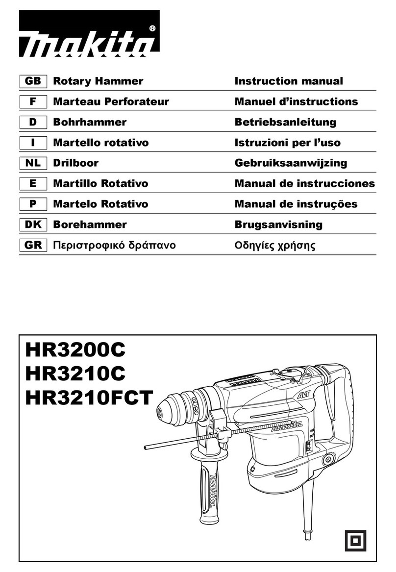
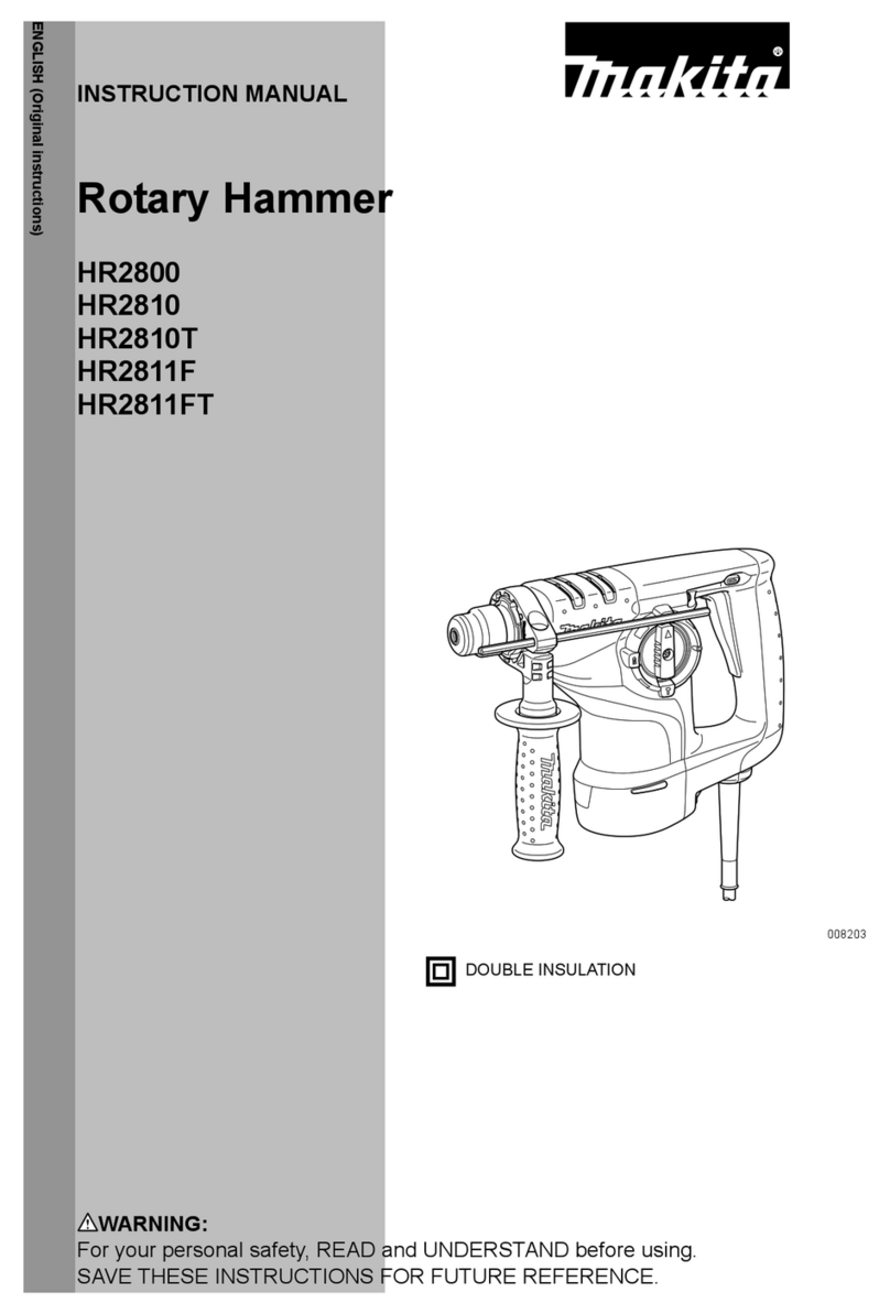
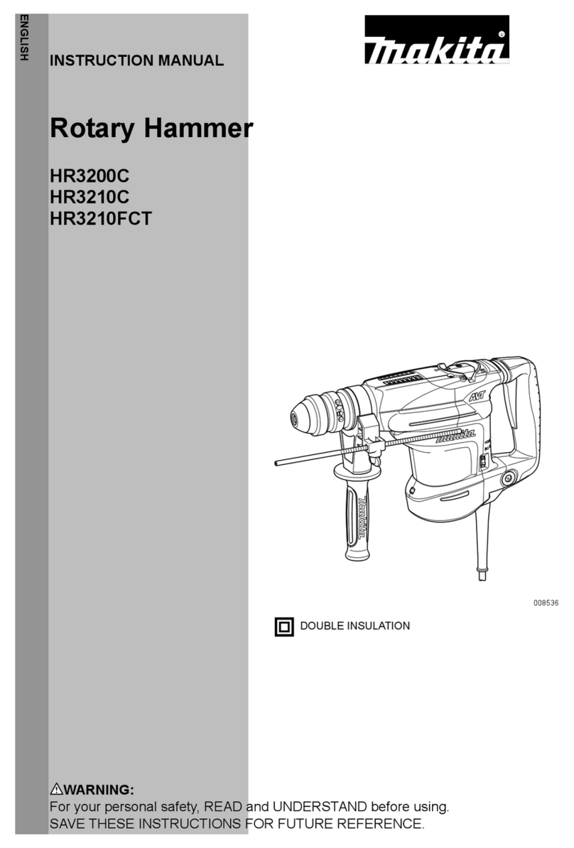
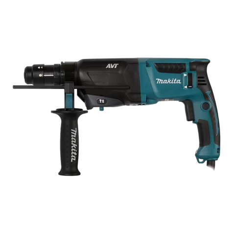
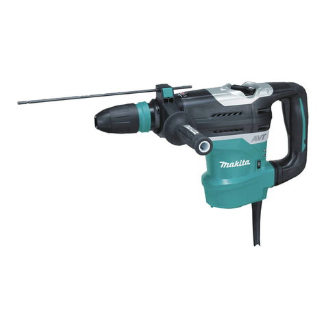
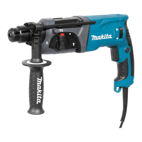
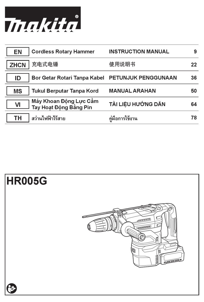
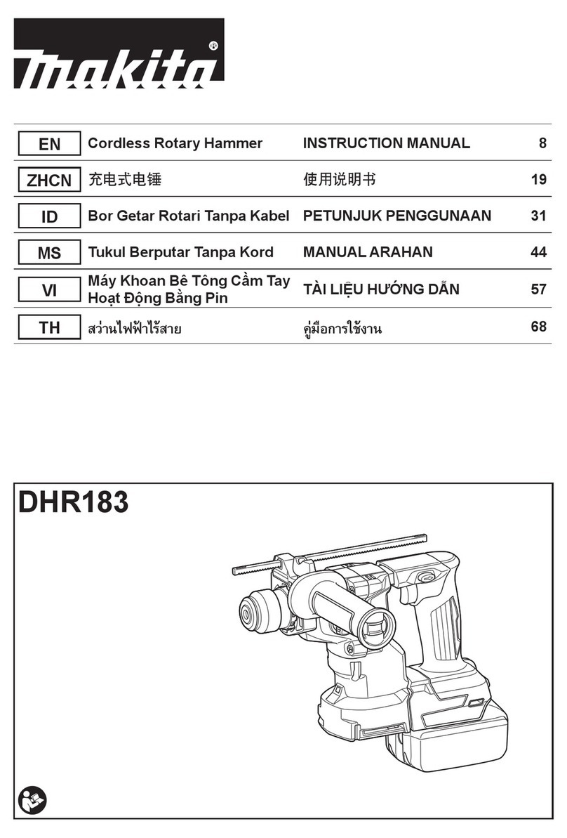
Makita BHR200 User manual

INSTRUCTION MANUAL
MANUEL D'INSTRUCTION
MANUAL DE INSTRUCCIONES
WARNING:
For your personal safety, READ and UNDERSTAND before using.
SAVE THESE INSTRUCTIONS FOR FUTURE REFERENCE.
AVERTISSEMENT:
Pour votre propre sécurité, prière de lire attentivement avant l’utilisation.
GARDER CES INSTRUCTIONS POUR RÉFÉRENCE ULTÉRIEURE.
ADVERTENCIA:
Para su seguridad personal, LEA DETENIDAMENTE este manual antes de usar la herramienta.
GUARDE ESTAS INSTRUCCIONES PARA FUTURA REFERENCIA.
Cordless Rotary Hammer
Marteau perforateur à batterie
Martillo Rotativo Inalámbrico
BHR200
003091

2
ENGLISH
SPECIFICATIONS
• Due to our continuing programme of research and development, the specifications herein are subject to change
without notice.
• Note: Specifications may differ from country to country.
GENERAL SAFETY RULES
USA003-2
(FOR ALL BATTERY OPERATED TOOLS)
WARNING:
Read and understand all instructions.
Failure to follow all instructions listed below,
may result in electric shock, fire and/or
serious personal injury.
SAVE THESE INSTRUCTIONS
Work Area
1. Keep your work area clean and well lit. Cluttered
benches and dark areas invite accidents.
2. Do not operate power tools in explosive atmo-
spheres, such as in the presence of flammable
liquids, gases, or dust. Power tools create sparks
which may ignite the dust or fumes.
3. Keep bystanders, children, and visitors away
while operating a power tool. Distractions can
cause you to lose control.
Electrical Safety
4. A battery operated tool with integral batteries or
a separate battery pack must be recharged only
with the specified charger for the battery. A
charger that may be suitable for one type of battery
may create a risk of fire when used with another bat-
tery.
5. Use battery operated tool only with specifically
designated battery pack. Use of any other batter-
ies may create a risk of fire.
Personal Safety
6. Stay alert, watch what you are doing, and use
common sense when operating a power tool. Do
not use tool while tired or under the influence of
drugs, alcohol, or medication. A moment of inat-
tention while operating power tools may result in
serious personal injury.
7. Dress properly. Do not wear loose clothing or
jewelry. Contain long hair. Keep your hair, cloth-
ing, and gloves away from moving parts. Loose
clothes, jewelry, or long hair can be caught in mov-
ing parts.
8. Avoid accidental starting. Be sure switch is in
the locked or off position before inserting bat-
tery pack. Carrying tools with your finger on the
switch or inserting the battery pack into a tool with
the switch on invites accidents.
9. Remove adjusting keys or wrenches before turn-
ing the tool on. A wrench or a key that is left
attached to a rotating part of the tool may result in
personal injury.
Model BHR200
Capacities
Concrete 20 mm (3/4”)
Steel 13 mm (1/2”)
Wood 27 mm (1-1/16”)
No load speed (RPM) 0 - 1,100/min.
Blows per minute 0 - 4,700
Overall length 316 mm (12-7/16”)
Net weight 4.0 kg (8.8 lbs)
Battery Charger DC24SA DC24WA
Input A.C. only 50 Hz - 60 Hz
Output D.C. 7.2 V - 24 V
Battery Cartridge BH2420 BH2433 BH2420 BH2433
Voltage 24 V
Charging time 30 min. 60 min. 55 min. 90 min.

3
10. Do not overreach. Keep proper footing and bal-
ance at all times. Proper footing and balance
enable better control of the tool in unexpected situa-
tions.
11. Use safety equipment. Always wear eye protec-
tion. Dust mask, non-skid safety shoes, hard hat, or
hearing protection must be used for appropriate con-
ditions.
Tool Use and Care
12. Use clamps or other practical way to secure and
support the workpiece to a stable platform. Hold-
ing the work by hand or against your body is unsta-
ble and may lead to loss of control.
13. Do not force tool. Use the correct tool for your
application. The correct tool will do the job better
and safer at the rate for which it is designed.
14. Do not use tool if switch does not turn it on or
off. A tool that cannot be controlled with the switch is
dangerous and must be repaired.
15. Disconnect battery pack from tool or place the
switch in the locked or off position before mak-
ing any adjustments, changing accessories, or
storing the tool. Such preventive safety measures
reduce the risk of starting the tool accidentally.
16. Store idle tools out of reach of children and
other untrained persons. Tools are dangerous in
the hands of untrained users.
17. When battery pack is not in use, keep it away
from other metal objects like: paper clips, coins,
keys, nails, screws, or other small metal objects
that can make a connection from one terminal to
another. Shorting the battery terminals together
may cause sparks, burns, or a fire.
18. Maintain tools with care. Keep cutting tools
sharp and clean. Properly maintained tools with
sharp cutting edge are less likely to bind and are
easier to control.
19. Check for misalignment or binding of moving
parts, breakage of parts, and any other condition
that may affect the tool’s operation. If damaged,
have the tool serviced before using. Many acci-
dents are caused by poorly maintained tools.
20. Use only accessories that are recommended by
the manufacturer for your model. Accessories
that may be suitable for one tool may create a risk of
injury when used on another tool.
SERVICE
21. Tool service must be performed only by qualified
repair personnel. Service or maintenance per-
formed by unqualified personnel may result in a risk
of injury.
22. When servicing a tool, use only identical
replacement parts. Follow instructions in the
Maintenance section of this manual. Use of unau-
thorized parts or failure to follow Maintenance
instructions may create a risk of shock or injury.
SPECIFIC SAFETY RULES
USB028-2
DO NOT let comfort or familiarity with
product (gained from repeated use)
replace strict adherence to cordless
rotary hammer safety rules. If you use
this tool unsafely or incorrectly, you can
suffer serious personal injury.
1. Hold tool by insulated gripping surfaces when
performing an operation where the cutting tool
may contact hidden wiring. Contact with a “live”
wire will make exposed metal parts of the tool “live”
and shock the operator.
2. Wear ear protectors when using the tool for
extended periods. Prolonged exposure to high
intensity noise can cause hearing loss.
3. Be aware that this tool is always in an operating
condition, because it does not have to be
plugged into an electrical outlet.
4. Wear a hard hat (safety helmet), safety glasses
and/or face shield. Ordinary eye or sun glasses
are NOT safety glasses. It is also highly recom-
mended that you wear a dust mask and thickly
padded gloves.
5. Be sure the bit is secured in place before opera-
tion.
6. Under normal operation, the tool is designed to
produce vibration. The screws can come loose
easily, causing a breakdown or accident. Check
tightness of screws carefully before operation.
7. In cold weather or when the tool has not been
used for a long time, let the tool warm up for sev-
eral minutes by operating it under no load. This
will loosen up the lubrication. Without proper
warm-up, hammering operation is difficult.
8. Always be sure you have a firm footing.
9. Be sure no one is below when using the tool in
high locations.
10. Hold the tool firmly with both hands.
11. Keep hands away from moving parts.
12. Do not leave the tool running. Operate the tool
only when hand-held.
13. Do not point the tool at any one in the area when
operating. The bit could fly out and injure some-
one seriously.
14. Do not touch the bit or parts close to the bit
immediately after operation; they may be
extremely hot and could burn your skin.
15. Some material contains chemicals which may be
toxic. Take caution to prevent dust inhalation
and skin contact. Follow material supplier safety
data.

4
SAVE THESE INSTRUCTIONS
WARNING:
MISUSE or failure to follow the safety
rules stated in this instruction manual
may cause serious personal injury.
SYMBOLS
USD302-1
The followings show the symbols used for tool.
V............................volts
.......................direct current
.......................no load speed
.../min....................revolutions or reciprocation per
minute
..................number of blow
IMPORTANT SAFETY
INSTRUCTIONS FOR CHARGER
& BATTERY CARTRIDGE
USC002-3
1. SAVE THESE INSTRUCTIONS- This manual con-
tains important safety and operating instruc-
tions for battery charger.
2. Before using battery charger, read all instruc-
tions and cautionary markings on (1) battery
charger, (2) battery, and (3) product using bat-
tery.
3. CAUTION - To reduce risk of injury, charge only
MAKITA rechargeable batteries marked on the
charger label. Other types of batteries may burst
causing personal injury and damage.
4. Do not expose charger to rain or snow.
5. Use of an attachment not recommended or sold
by the battery charger manufacturer may result
in a risk of fire, electric shock, or injury to per-
sons.
6. To reduce risk of damage to electric plug and
cord, pull by plug rather than cord when discon-
necting charger.
7. Make sure cord is located so that it will not be
stepped on, tripped over, or otherwise subjected
to damage or stress.
8. An extension cord should not be used unless
absolutely necessary. Use of improper extension
cord could result in a risk of fire and electric
shock. If extension cord must be used, make
sure:
a. That pins on plug of extension cord are the
same number, size, and shape as those of
plug on charger;
b. That extension cord is properly wired and in
good electrical condition; and
c. That wire size is at least as large as the one
specified in the table below.
9. Do not operate charger with damaged cord or
plug - replace them immediately.
10. Do not operate charger if it has received a sharp
blow, been dropped, or otherwise damaged in
any way; take it to a qualified serviceman.
11. Do not disassemble charger or battery cartridge;
take it to a qualified serviceman when service or
repair is required. Incorrect reassembly may
result in a risk of electric shock or fire.
12. To reduce risk of electric shock, unplug charger
from outlet before attempting any maintenance
or cleaning. Turning off controls will not reduce
this risk.
13. The battery charger is not intended for use by
young children or infirm persons without super-
vision.
14. Young children should be supervised to ensure
that they do not play with the battery charger.
15. If operating time has become excessively
shorter, stop operating immediately. It may
result in a risk of overheating, possible burns
and even an explosion.
16. If electrolyte gets into your eyes, rinse them out
with clear water and seek medical attention right
away. It may result in loss of your eyesight.
ADDITIONAL SAFETY RULES
FOR CHARGER & BATTERY
CARTRIDGE
1. Do not charge Battery Cartridge when tempera-
ture is BELOW 10°C (50°F) or ABOVE 40°C
(104°F).
2. Do not attempt to use a step-up transformer, an
engine generator or DC power receptacle.
Table 1: RECOMMENDED MINIMUM AWG SIZE FOR EXTENSION CORDS FOR BATTERY CHARGERS
Length of Cord (Feet) 25 50 100 150
AWG Size of Cord 18 18 18 16

5
3. Do not allow anything to cover or clog the
charger vents.
4. Do not short the battery cartridge:
(1) Do not touch the terminals with any conduc-
tive material.
(2) Avoid storing battery cartridge in a con-
tainer with other metal objects such as nails,
coins, etc.
(3) Do not expose battery cartridge to water or
rain.
A battery short can cause a large current flow,
overheating, possible burns and even a break-
down.
5. Do not store the tool and Battery Cartridge in
locations where the temperature may reach or
exceed 50°C (122°F).
6. Do not incinerate the Battery Cartridge even if it
is severely damaged or is completely worn out.
The battery cartridge can explode in a fire.
7. Be careful not to drop, shake or strike battery.
8. Do not charge inside a box or container of any
kind. The battery must be placed in a well venti-
lated area during charging.
SAVE THESE INSTRUCTIONS
SYMBOLS
The following show the symbols used for the charger. Be
sure that you understand their meaning before use.
............Ready to charge
...............Charging
...............Charging complete
...........Delay charge (Cooling)
...........Defective battery
...........Conditioning
............Cooling abnormality
FUNCTIONAL DESCRIPTION
CAUTION:
•Always be sure that the tool is switched off and the
battery cartridge is removed before adjusting or
checking function on the tool.
Installing or removing battery cartridge
•Always switch off the tool before insertion or
removal of the battery cartridge.
•To remove the battery cartridge, withdraw it from
the tool while sliding the button on the side of the
cartridge.
•To insert the battery cartridge, align the tongue on
the battery cartridge with the groove in the housing
and slip it into place. Always insert it all the way
until it locks in place with a little click. If you can see
the red part on the upper side of the button, it is not
locked completely. Insert it fully until the red part
cannot be seen. If not, it may accidentally fall out of
the tool, causing injury to you or someone around
you.
•Do not use force when inserting the battery
cartridge. If the cartridge does not slide in easily, it
is not being inserted correctly.
Charging
1. Plug the battery charger into the proper AC voltage
source. Two charging lights will flash in green color
repeatedly.
2. Insert the battery cartridge into charger until it stops
adjusting to the guide of charger. Terminal cover of
charger can be opened with inserting and closed
with pulling out the battery cartridge.
3. When the battery cartridge is inserted, the charging
light color will change from green to red and charg-
ing will begin. The charging light will keep lighting
up lit steadily during charging. One red charging
light indicates charged condition in 0 - 80% and two
red ones indicates 80 - 100%.
4. With finish of charge, the charging lights will
change from two red ones to two green ones.
1. Battery car-
tridge
2. Red part
3. Button
1. Terminal cover
2. Battery car-
tridge
3. Charging light
4. Battery charger
13
2
003103
1
2
3
4
001336

6
5. If you leave the battery cartridge in the charger
after the charging cycle is complete, the charger
will switch into its “trickle charge (maintenance
charge)”mode which will last approximately 24
hours.
6. After charging, unplug the charger from the power
source.
NOTE:
•The battery charger is for charging Makita battery
cartridge. Never use it for other purposes or for
other manufacturer’s batteries.
•When you charge a new battery cartridge or a
battery cartridge which has not been used for a
long period of time, it may not accept a full charge.
This is a normal condition and does not indicate a
problem. You can recharge the battery cartridge
fully after discharging it completely and recharging
a couple of times.
•If you charge a battery cartridge from a just
operated tool or battery cartridge which has been
left in a location exposed to direct sunlight for a long
time, the charging light may flash in red color. If this
occurs, wait for a while. Charging will begin after
the battery cartridge is cooled by the cooling fan
installed in the charger. (DC24SA only) When the
temperature on battery is more than approx. 70°C,
two charging lights may flash in red color, and when
approx. 50°C - 70°C, one charging light in red color.
•If the charging light flashes alternately in green and
red color, charging is not possible. The terminals on
the charger or battery cartridge are clogged with
dust or the battery cartridge is worn out or
damaged.
Cooling system (DC24SA only)
•This charger is equipped with cooling fan for heated
battery in order to enable the battery to prove its
own performance. Sound of cooling air comes out
during cooling, which means no trouble on the
charger.
•Yellow light will flash for warning in the following
cases.
- Trouble on cooling fan
- Incomplete cool down of battery, such as, being
clogged with dust
The battery can be charged in spite of the yellow
warning light. But the charging time will be longer
than usual in this case. Check the sound of cooling
fan, vent on the charger and battery, which can be
sometime clogged with dust.
•The cooling system is in order although no sound of
cooling fan comes out, if the yellow warning light
will not flash.
•Always keep clean the vent on charger and battery
for cooling.
•The products should be sent to repair or
maintenance, if the yellow warning light will
frequently flash.
Conditioning charge (DC24SA only)
Conditioning charge can extend the life of battery by
automatically searching the optimum charging condition
for the batteries in every situations.
The battery employed in the following conditions repeat-
edly, will be worn out shortly, and yellow warning light
may flash.
1. Recharge of battery with its high temperature
2. Recharge of battery with its low temperature
3. Recharge of full charged battery
4. Over-discharge of battery (continue to discharge
battery in spite of down of power.)
The charging time of such battery is longer than usual.
Trickle charge (Maintenance charge)
If you leave the battery cartridge in the charger to prevent
spontaneous discharging after full charge, the charger
will switch into its “trickle charge (maintenance charge)”
mode and keep the battery cartridge fresh and fully
charged.
Tips for maintaining maximum battery life
1. Charge the battery cartridge before completely dis-
charged.
Always stop tool operation and charge the battery
cartridge when you notice less tool power.
2. Never recharge a fully charged battery cartridge.
Overcharging shortens the battery service life.
3. Charge the battery cartridge with room temperature
at 10°C - 40°C (50°F - 104°F).
Let a hot battery cartridge cool down before charg-
ing it.
4. Charge the Nickel Metal Hydride battery cartridge
when you do not use it for more than six months.
Switch action
CAUTION:
•Before inserting the battery cartridge into the tool,
always check to see that the switch trigger actuates
properly and returns to the “OFF”position when
released.
To start the tool, simply pull the switch trigger. Tool speed
is increased by increasing pressure on the switch trigger.
Release the switch trigger to stop.
1. Switch trigger
1
003104

7
Electric brake
This tool is equipped with an electric brake. If the tool
consistently fails to quickly stop after switch trigger
release, have tool serviced at a Makita service center.
Reversing switch action
This tool has a reversing switch to change the direction of
rotation. Depress the reversing switch lever from the A
side for clockwise rotation or from the B side for counter-
clockwise rotation.
When the reversing switch lever is in the neutral position,
the switch trigger cannot be pulled.
CAUTION:
•Always check the direction of rotation before
operation.
•Use the reversing switch only after the tool comes
to a complete stop. Changing the direction of
rotation before the tool stops may damage the tool.
•When not operating the tool, always set the
reversing switch lever to the neutral position.
Selecting the action mode
Rotation with hammering
For drilling in concrete, masonry, etc., depress the lock
button and rotate the change lever so that the pointer
points to the symbol. Use a tungsten-carbide tipped
bit.
Rotation only
For drilling in wood, metal or plastic materials, depress
the lock button and rotate the change lever so that the
pointer points to the symbol. Use a twist drill bit or
wood bit.
Hammering only
For chipping, scaling or demolition operations, depress
the lock button and rotate the change lever so that the
pointer points to the symbol. Use a bull point, cold
chisel, scaling chisel, etc.
CAUTION:
•Do not rotate the change lever when the tool is
running. The tool will be damaged.
•To avoid rapid wear on the mode change
mechanism, be sure that the change lever is always
positively located in one of the three action mode
positions.
Torque limiter
The torque limiter will actuate when a certain torque level
is reached. The motor will disengage from the output
shaft. When this happens, the bit will stop turning.
CAUTION:
•As soon as the torque limiter actuates, switch off
the tool immediately. This will help prevent
premature wear of the tool.
1. Reversing
switch lever
1. Rotation with
hammering
2. Lock button
3. Pointer
4. Change lever
AB
1
003113
12
3
4
003128
1. Rotation only
2. Pointer
1. Hammering only
2. Pointer
1
2
003131
1
2
003133

8
ASSEMBLY
CAUTION:
•Always be sure that the tool is switched off and the
battery cartridge is removed before carrying out
any work on the tool.
Side grip
The side grip swings around to either side, allowing easy
handling of the tool in any position. Loosen the side grip
by turning it counterclockwise, swing it to the desired
position and then tighten it by turning clockwise.
Bit grease (optional accessory)
Coat the bit shank head beforehand with a small amount
of bit grease (about 0.5 -1 g; 0.02 - 0.04 oz.). This chuck
lubrication assures smooth action and longer service life.
Installing or removing the bit
Clean the bit shank and apply bit grease before installing
the bit.
Insert the bit into the tool. Turn the bit and push it in until
it engages.
If the bit cannot be pushed in, remove the bit. Pull the
chuck cover down a couple of times. Then insert the bit
again. Turn the bit and push it in until it engages.
After installing, always make sure that the bit is securely
held in place by trying to pull it out.
To remove the bit, pull the chuck cover down all the way
and pull the bit out.
Bit angle
(when chipping, scaling or demolishing)
To change the bit angle, depress the lock button and
rotate the change lever so that the pointer points to the
“O”symbol. Turn the bit to the desired angle.
Depress the lock button and rotate the change lever so
that the pointer points to the symbol. Then make sure
that the bit is securely held in place by turning it slightly.
1. Side grip
1. Bit shank
2. Bit grease
1. Bit
2. Chuck cover
1
003141
2
1
003150
1
2
003157
1. Change lever
2. O symbol
1. Change lever
003166
12
003170
1
003174

9
Depth gauge
The depth gauge is convenient for drilling holes of uni-
form depth. Insert the depth gauge into the hole in the
grip base. Adjust the depth gauge to the desired depth
and then tighten the clamp screw to secure the depth
gauge.
NOTE:
•The depth gauge cannot be used at the position
where the depth gauge strikes against the tool
body.
Dust cup (optional accessory)
Use the dust cup to prevent dust from falling over the tool
and on yourself when performing overhead drilling opera-
tions. Attach the dust cup to the bit as shown in the fig-
ure. The size of bits which the dust cup can be attached
to is as follows.
OPERATION
CAUTION:
•Always insert the battery cartridge all the way until
it locks in place. If you can see the red part on the
upper side of the button, it is not locked completely.
Insert it fully until the red part cannot be seen. If
not, it may accidentally fall out of the tool, causing
injury to you or someone around you.
•When operating overhead, always make sure the
battery cartridge is locked securely so that it will not
be fallen out of the tool. If not, it may accidentally
fall out of the tool, causing injury to you or someone
around you.
Hammer drilling operation
Set the change lever to the symbol.
Position the bit at the desired location for the hole, then
pull the switch trigger. Do not force the tool. Light pres-
sure gives best results. Keep the tool in position and pre-
vent it from slipping away from the hole.
Do not apply more pressure when the hole becomes
clogged with chips or particles. Instead, run the tool at an
idle, then remove the bit partially from the hole. By
repeating this several times, the hole will be cleaned out
and normal drilling may be resumed.
CAUTION:
•There is a tremendous and sudden twisting force
exerted on the tool/bit at the time of hole break-
through, when the hole becomes clogged with
chips and particles, or when striking reinforcing
rods embedded in the concrete. Always use the
side grip (auxiliary handle) and firmly hold the tool
by both side grip and switch handle during
operations. Failure to do so may result in the loss of
control of the tool and potentially severe injury.
Blow-out bulb (optional accessory)
After drilling the hole, use the blow-out bulb to clean the
dust out of the hole.
Chipping/Scaling/Demolition
1. Depth gauge
2. Clamp screw
3. Grip base
1. Dust cup
12 3
003179
1
003186
Bit diameter
Dust cup 5 6 mm (1/4") - 14.5 mm (9/16")
Dust cup 9 12 mm (15/32") - 16 mm (5/8")
006382
1. Blow-out bulb
003197
1
002449
003203

10
Set the change lever to the symbol.
Hold the tool firmly with both hands. Turn the tool on and
apply slight pressure on the tool so that the tool will not
bounce around, uncontrolled. Pressing very hard on the
tool will not increase the efficiency.
Drilling in wood or metal
Use the optional drill chuck assembly. When installing it,
refer to “Installing or removing the bit”described on the
previous page.
Set the change lever so that the pointer points to the
symbol.
You can drill up to 13 mm (1/2”) diameter in metal and up
to 27 mm (1-1/16”) diameter in wood.
CAUTION:
•Never use “rotation with hammering”when the drill
chuck assembly is installed on the tool. The drill
chuck assembly may be damaged.
Also, the drill chuck will come off when reversing
the tool.
•Pressing excessively on the tool will not speed up
the drilling. In fact, this excessive pressure will only
serve to damage the tip of your bit, decrease the
tool performance and shorten the service life of the
tool.
•There is a tremendous twisting force exerted on the
tool/bit at the time of hole breakthrough. Hold the
tool firmly and exert care when the bit begins to
break through the workpiece.
•A stuck bit can be removed simply by setting the
reversing switch to reverse rotation in order to back
out. However, the tool may back out abruptly if you
do not hold it firmly.
•Always secure small workpieces in a vise or similar
hold-down device.
MAINTENANCE
CAUTION:
•Always be sure that the tool is switched off and the
battery cartridge is removed before attempting to
perform inspection or maintenance.
Replacing carbon brushes
Remove and check the carbon brushes regularly.
Replace when they wear down to the limit mark. Keep
the carbon brushes clean and free to slip in the holders.
Both carbon brushes should be replaced at the same
time. Use only identical carbon brushes.
Use a screwdriver to remove the brush holder caps. Take
out the worn carbon brushes, insert the new ones and
secure the brush holder caps.
After replacing brushes, insert the battery cartridge into
the tool and break in brushes by running tool with no load
for about 1 minute. Then check the tool while running and
electric brake operation when releasing the switch trig-
ger. If electric brake is not working well, ask your local
Makita service center for repair.
To maintain product SAFETY and RELIABILITY, repairs,
any other maintenance or adjustment should be per-
formed by Makita Authorized or Factory Service Centers,
always using Makita replacement parts.
1. Drill chuck
2. Change lever
3. Pointer
1
2
3
003222
1. Limit mark
1. Brush holder
cap
2. Screwdriver
1
001145
1
2
003228

11
ACCESSORIES
CAUTION:
•These accessories or attachments are
recommended for use with your Makita tool
specified in this manual. The use of any other
accessories or attachments might present a risk of
injury to persons. Only use accessory or
attachment for its stated purpose.
If you need any assistance for more details regarding
these accessories, ask your local Makita Service Center.
•SDS-Plus Carbide-tipped bits
•Bull point
•Cold chisel
•Drill chuck assembly
•Drill chuck S13
•Chuck adapter
•Chuck key S13
•Bit grease
•Grip assembly
•Depth gauge
•Blow-out bulb
•Dust cup
•Dust extractor attachment
•Safety goggles
•Plastic carrying case
EN0006-1
MAKITA LIMITED ONE YEAR WARRANTY
Warranty Policy
Every Makita tool is thoroughly inspected and tested
before leaving the factory. It is warranted to be free of
defects from workmanship and materials for the period of
ONE YEAR from the date of original purchase. Should
any trouble develop during this one year period, return
the COMPLETE tool, freight prepaid, to one of Makita’s
Factory or Authorized Service Centers. If inspection
shows the trouble is caused by defective workmanship or
material, Makita will repair (or at our option, replace)
without charge.
This Warranty does not apply where:
•repairs have been made or attempted by others:
•repairs are required because of normal wear and
tear:
•the tool has been abused, misused or improperly
maintained:
•alterations have been made to the tool.
IN NO EVENT SHALL MAKITA BE LIABLE FOR ANY
INDIRECT, INCIDENTAL OR CONSEQUENTIAL DAM-
AGES FROM THE SALE OR USE OF THE PRODUCT.
THIS DISCLAIMER APPLIES BOTH DURING AND
AFTER THE TERM OF THIS WARRANTY.
MAKITA DISCLAIMS LIABILITY FOR ANY IMPLIED
WARRANTIES, INCLUDING IMPLIED WARRANTIES
OF “MERCHANTABILITY”AND “FITNESS FOR A SPE-
CIFIC PURPOSE,”AFTER THE ONE YEAR TERM OF
THIS WARRANTY.
This Warranty gives you specific legal rights, and you
may also have other rights which vary from state to state.
Some states do not allow the exclusion or limitation of
incidental or consequential damages, so the above limi-
tation or exclusion may not apply to you. Some states do
not allow limitation on how long an implied warranty lasts,
so the above limitation may not apply to you.

12
FRANÇAIS
SPÉCIFICATIONS
•Le fabricant se réserve le droit de modifier sans avertissement les spécifications.
•Note: Les spécifications peuvent varier selon les pays.
RÈGLES DE SÉCURITÉ
GÉNÉRALES
USA003-2
(POUR TOUS LES OUTILS ALIMENTÉS
PAR BATTERIE)
AVERTISSEMENT:
Vous devez lire et comprendre toutes les
instructions. Le non-respect, même partiel,
des instructions ci-après entraîne un risque
de choc électrique, d’incendie et/ou de
blessures graves.
CONSERVEZ CES
INSTRUCTIONS
Aire de travail
1. Veillez à ce que l’aire de travail soit propre et
bien éclairée. Le désordre et le manque de lumière
favorisent les accidents.
2. N’utilisez pas d’outils électriques dans une
atmosphère explosive, par exemple en présence
de liquides, de gaz ou de poussières
inflammables. Les outils électriques créent des
étincelles qui pourraient enflammer les poussières
ou les vapeurs.
3. Tenez à distance les curieux, les enfants et les
visiteurs pendant que vous travaillez avec un
outil électrique. lls pourraient vous distraire et vous
faire une fausse manoeuvre.
Sécurité électrique
4. Un outil alimenté par une batterie intégrée ou un
bloc-pile séparé ne doit être rechargé qu’au
moyen du chargeur spécifié pour la batterie en
question. Un chargeur qui convient àun type donné
de batterie peut comporter un risque d’incendie
lorsqu’il est utilisépour charger un autre type de
batterie.
5. N’utilisez un outil alimenté par batterie qu’avec
le bloc-pile spécifié pour l’outil en question.
L’utilisation de toute autre batterie peut comporter un
risque d’incendie.
Sécurité des personnes
6. Restez alerte, concentrez-vous sur votre travail
et faites preuve de jugement. N’utilisez pas un
outil électrique si vous êtes fatigué ou sous
l’influence de drogues, d’alcool ou de
médicaments. Un instant d’inattention suffit pour
entraîner des blessures graves.
7. Habillez-vous convenablement. Ne portez ni
vêtements flottants ni bijoux. Confinez les
cheveux longs. N’approchez jamais les
Modèle BHR200
Capacités
Béton 20 mm (3/4”)
Acier 13 mm (1/2”)
Bois 27 mm (1-1/16”)
Vitesse àvide (T/MIN) 0 - 1,100/min.
Nombre de frappes par minute 0 - 4,700
Longueur totale 316 mm (12-7/16”)
Poids net 4.0 kg (8.8 lbs)
Chargeur de batterie DC24SA DC24WA
Entrée C.A. only 50 Hz - 60 Hz
Sortie C.C. 7.2 V - 24 V
Cartouche de batterie BH2420 BH2433 BH2420 BH2433
Tension 24 V
Temps de charge 30 min. 60 min. 55 min. 90 min.

13
cheveux, les vêtements ou les gants des pièces
en mouvement. Des vêtements flottants, des bijoux
ou des cheveux longs risquent d’être happés par
des pièces en mouvement.
8. Méfiez-vous d’un démarrage accidentel. Avant
d’insérer la batterie, assurez-vous que
l’interrupteur est en position de verrouillage ou
d’arrêt. Vous risquez de provoquer un accident si
vous transportez les outils en gardant le doigt sur
l’interrupteur ou en laissant l’interrupteur en position
de marche lors de l’insertion du bloc-pile.
9. Enlevez les clés de réglage ou de serrage avant
de démarrer l’outil. Une clélaissée dans une pièce
tournante de l’outil peut provoquer des blessures.
10. Ne vous penchez pas trop en avant. Maintenez
un bon appui et restez en équilibre en tout
temps. Un bonne stabilitévous permet de mieux
réagir àune situation inattendue.
11. Utilisez des accessoires de sécurité. Portez
toujours des lunettes ou une visière. Selon les
conditions, portez aussi un masque antipoussière,
des bottes de sécuritéantidérapantes, un casque
protecteur et/ou un appareil antibruit.
Utilisation et entretien des outils
12. Immobilisez le matériau sur une surface stable
au moyen de brides ou de toute autre façon
adéquate. Le fait de tenir la pièce avec la main ou
contre votre corps offre une stabilitéinsuffisante et
peut amener un dérapage de l’outil.
13. Ne forcez pas l’outil. Utilisez l’outil approprié à
la tâche. L’outil correct fonctionne mieux et de façon
plus sécuritaire. Respectez aussi la vitesse de
travail qui lui est propre.
14. N’utilisez pas un outil si son interrupteur est
bloqué. Un outil que vous ne pouvez pas
commander par son interrupteur est dangereux et
doit être réparé.
15. Déconnectez le bloc-pile de l’outil ou placez
l’interrupteur en position de verrouillage ou
d’arrêt avant d’effectuer des réglages, de
changer les accessoires ou de ranger l’outil. De
telles mesures préventives de sécuritéréduisent le
risque de démarrage accidentel de l’outil.
16. Rangez les outils hors de la portée des enfants
et d’autres personnes inexpérimentées. Les
outils sont dangereux dans les mains d’utilisateurs
novices.
17. Lorsque le bloc-pile n’est pas utilisé, rangez-le à
l’écart des autres objets métalliques tels que:
trombones, pièces de monnaie, clés, clous, vis
ou autres petits objets métalliques susceptibles
d’établir le contact entre les bornes. La mise en
court-circuit des bornes de la batterie peut
provoquer des étincelles, des brûlures ou un
incendie.
18. Prenez soin de bien entretenir les outils. Les
outils de coupe doivent être toujours bien
affûtés et propres. Des outils bien entretenus, dont
les arêtes sont bien tranchantes, sont moins
susceptibles de coincer et plus faciles àdiriger.
19. Soyez attentif à tout désalignement ou
coincement des pièces en mouvement, à tout
bris ou à toute autre condition préjudiciable au
bon fonctionnement de l’outil. Si vous constatez
qu’un outil est endommagé, faites-le réparer
avant de vous en servir. De nombreux accidents
sont causés par des outils en mauvais état.
20. N’utilisez que des accessoires que le fabricant
recommande pour votre modèle d’outil. Des
accessoires adéquats pour un outil donnépeuvent
comporter un risque de blessure lorsque utilisés sur
un autre outil.
Réparation
21. La réparation des outils électriques doit être
confiée à un réparateur qualifié. L’entretien ou la
réparation d’un outil électrique par un amateur peut
avoir des conséquences graves.
22. Pour la réparation d’un outil, n’employez que
des pièces de rechange d’origine. Suivez les
directives données à la section «ENTRETIEN» de
ce manuel. L’emploi de pièces non autorisées ou le
non-respect des instructions d’entretien peut créer
un risque de choc électrique ou de blessures.
RÈGLES DE SÉCURITÉ
PARTICULIÈRES
USB028-2
NE vous laissez PAS tromper (au fil d’une
utilisation répétée) par un sentiment
d’aisance et de familiarité avec le
produit, en négligeant le respect
rigoureux des consignes de sécurité qui
accompagnent le marteau perforateur à
batterie. L’utilisation non sécuritaire ou
incorrecte de cet outil comporte un
risque de blessure grave.
1. Tenez l’outil par ses surfaces de prise isolées
pendant toute opération où l’outil de coupe
pourrait venir en contact avec un câblage
dissimulé. En cas de contact avec un conducteur
sous tension, les pièces métalliques àdécouvert de
l’outil transmettraient un choc électrique à
l’utilisateur.
2. Portez un appareil antibruit si vous devez utiliser
l’outil pendant une période prolongée. Une
exposition prolongée àun bruit de forte intensité
peut entraîner des lésions de l’ouïe.
3. Ayez bien conscience que l’outil est
constamment en état de marche, car il n’a pas à
être raccordé au secteur.

14
4. Portez un casque rigide (casque de protection)
ainsi que des lunettes de sécurité et/ou un écran
facial. Les lunettes ordinaires et les lunettes de
soleil ne constituent PAS des lunettes de
sécurité. Le port d’un masque à poussière et de
gants épais est également fortement
recommandé.
5. Assurez-vous que le foret est solidement installé
avant l’utilisation.
6. L’outil est conçu pour produire des vibrations
dans des conditions normales d’utilisation. Les
vis peuvent facilement se desserrer et entraîner
une panne ou un accident. Avant l’utilisation,
vérifiez soigneusement si les vis sont bien
serrées.
7. Par temps froid ou lorsque l’outil est resté
inutilisé pendant une longue période, faites-le
réchauffer pendant quelques minutes en le
faisant fonctionner à vide. Cela réchauffera le
lubrifiant. Sans un réchauffement adéquat, le
martelage s’effectue difficilement.
8. Assurez-vous toujours de travailler en position
stable.
9. Lorsque vous utilisez l’outil dans un endroit
élevé, assurez-vous qu’il n’y a personne en bas.
10. Tenez l’outil fermement à deux mains.
11. Gardez les mains éloignées des pièces en
mouvement.
12. Ne laissez pas l’outil tourner. Ne le faites
fonctionner que lorsque vous le tenez.
13. Ne pointez l’outil vers personne autour de vous
pendant l’utilisation. Le foret pourrait être éjecté
et blesser quelqu’un grièvement.
14. Ne touchez pas le foret ou les parties situées
près du foret immédiatement après l’utilisation ;
ils peuvent être extrêmement chauds et brûler
votre peau.
15. Certains matériaux contiennent des produits
chimiques qui peuvent être toxiques. Prenez les
précautions nécessaires pour éviter que la
poussière dégagée lors du travail ne soit inhalée
ou n’entre en contact avec la peau. Suivez les
consignes de sécurité du fournisseur du
matériau.
CONSERVEZ CES
INSTRUCTIONS
AVERTISSEMENT:
LA MAUVAISE UTILISATION de l’outil ou
l’ignorance des consignes de sécurité du
présent manuel d’instructions peuvent
entraîner une grave blessure.
SYMBOLES
USD302-1
Les symboles utilisés pour l’outil sont présentés ci-
dessous.
V...........................volts
.......................courant continu
.......................vitesse àvide
.../min ...................tours ou alternances par minute
.................. nombre de frappes
PRECAUTIONS TRES
IMPORTANTES POUR LE
CHARGEUR ET LA
PILE-CARTOUCHE
USC002-3
1. SUIVEZ CES INSTRUCTIONS - Ce manuel
contient d’importantes instructions relatives à la
sécurité et au fonctionnement du chargeur de
piles.
2. Avant de vous servir du chargeur, lisez toutes
les instructions et précautions relatives 1) au
chargeur, 2) à la pile, et 3) à l’outil utilisant la
pile.
3. PRECAUTION – Pour réduire les risques de
blessures, n'utiliser que des batteries
rechargeables MAKITA marquées sur l'étiquette
du chargeur. Tout autre type de batterie risque
d'exploser en provoquant des blessures et des
dommages.
4. N’exposez pas le chargeur à la pluie ou à la
neige.
5. L’utilisation d’un accessoire non recommandé ni
vendu par le fabricant du chargeur peut
entraîner un risque d’incendie, de décharge
électrique ou de blessure.
6. Pour ne pas risquer d’endommager le câble ou
la prise, débranchez en tenant la prise plutôt
quele câble.
7. Assurez-vous que la position du câble ne
l’expose pas à faire trébucher, à être foulé aux
pieds, ou à forcer de quelque manière que ce
soit.
8. Ne pas utiliser de cordon de rallonge à moins de
nécessité absolue. L'emploi d'un cordon de
rallonge inadéquate risque d'entraîner un
incendie et une électrocution. S'il est impossible
de s'en passer, s'assurer:
a. Que les broches de la fiche du cordon de
rallonge soient en nombre égal, et
correspondant en grandeur et en forme à la
prise du chargeur.

15
b. Que le cordon de rallonge soit
convenablement connecté et en bon état du
point de vue électrique.
c. Que les dimensions du câblage soient au
moins de caractéristiques équivalentes à
celles spécifiées dans le tableau ci-dessous.
9. Ne pas utiliser le chargeur avec une fiche ou un
cordon endommagé – Les remplacer
immédiatement si besoin.
10. Si le chargeur a subi un choc, a tombé, ou a été
endommagé de manière quelconque, ne pas
s’en servir; l’apporter pour réparation chez un
technicien qualifié.
11. Ne pas désassembler le chargeur ni la cartouche
de batterie; l’apporter pour réparation chez un
technicien qualifié si besoin. Un réassemblage
inadéquate risquerait d’entraîner une
électrocution ou un incendie.
12. Pour réduire le risque d’électrocution,
débrancher le chargeur de la prise
d’alimentation avant d’entreprendre toute
opération d’entretien ou de nettoyage. La
coupure des interrupteurs s’avère insuffisante
pour réduire ce risque.
13. Le chargeur de batterie ne doit pas être
manipulé par les jeunes enfants ou les
personnes infirmes sans surveillance.
14. Il convient de veiller à ce que les jeunes enfants
ne jouent pas avec le chargeur de batterie.
15. Si la durée de fonctionnement est devenue
excessivement courte, arrêter le fonctionnement
immédiatement. Autrement, cela risquerait de
provoquer le surchauffement, voire des brûlures
et même une déflagration.
16. Si par inadvertance de l’électrolyte atteignait les
yeux, il faudrait les rincer aussitôt à l’eau propre
et consulter un médecin le plus vite possible,
autrement, la faculté oculaire risquerait d’être
compromise.
PRECAUTIONS
SUPPLEMENTAIRES POUR LE
CHARGEUR ET LA
PILE-CARTOUCHE
1. Ne pas charger la cartouche de batterie lorsque
la température ambiante est INFERIEURE à 10°C
ou SUPERIEURE à 40°C.
2. Ne tentez pas d’utiliser un transformateur-
élévateur, un groupe électrogène ou une prise de
courant continu.
3. Ne laissez rien recouvrir ou obturer les
ouvertures du chargeur.
4. Ne pas causer de court-circuit à la cartouche de
batterie:
(1) Ne jamais toucher les bornes de
raccordement avec des matériaux
conducteurs.
(2) Ne pas conserver la batterie dans un
récipient contenant des objets métalliques
tels que des clous, des pièces métalliques,
etc.
(3) Ne pas exposer la batterie à l’eau ni à la
pluie.
Un court-circuit à la batterie risque de causer
une surintensité de courant, un surchauffement,
voire une calcination et même une panne.
5. Ne rangez pas votre outil ou votre pile-cartouche
dans des endroits où la température risque de
dépasser 50°
6. Ne brûlez pas la pile-cartouche même si elle est
sévèrement endommagée ou complètement
hors d’usage, car elle risque d’exploser au feu.
7. Prendre garde de ne pas laisser tomber, secouer
ou heurter la batterie.
8. Ne pas charger à l’intérieur d’une boîte ou d’un
containeur de toutes sortes. La batterie doit être
placée dans un endroit bien ventilé durant
l’opération de charge.
SUIVEZ STRICTEMENT CES
INSTRUCTIONS
SYMBOLS
Les symboles suivants concernent le chargeur. Bien se
familiariser avec leur signification avant l’utilisation.
............Prêt àla charge
...............Charge
...............Charge terminée
...........Délai de charge (Refroidissement)
...........Batterie défectueuse
TABLEAU 1: GRANDEUR AWG MINIMUM RECOMMENDEE POUR LES CORDONS DE
RALLONGE DES CHARGEURS DE BATTERIE.
Longueur du cordon (Pieds) 25 50 100 150
Grandeur AWG du cordon 18 18 18 16

16
...........Conditionnement
............Anomalie de refroidissement
DESCRIPTION DU
FONCTIONNEMENT
ATTENTION:
•Assurez-vous toujours que l’outil est hors tension et
que sa batterie est retirée avant de l’ajuster ou de
vérifier son fonctionnement.
Installation ou retrait de la batterie
•Mettez toujours l’outil hors tension avant d’insérer
ou de retirer la batterie.
•Pour retirer la batterie, sortez-la de l’outil tout en
faisant glisser le bouton sur le côtéde la batterie.
•Pour insérer la batterie, alignez sa languette sur
l’entaille qui se trouve àl’intérieur du carter, puis
glissez la batterie pour la mettre en place. Insérez-
la toujours bien àfond, jusqu’à ce qu’elle se
verrouille en émettant un léger clic. Si vous pouvez
voir la partie rouge de la face supérieure du bouton,
la batterie n’est pas parfaitement verrouillée.
Insérez-la àfond, jusqu’à ce que la partie rouge ne
soit plus visible. Sinon, elle risque de tomber
accidentellement de l’outil, en vous blessant ou en
blessant une personne se trouvant près de vous.
•N’appliquez pas une force excessive lors de
l’insertion de la batterie. Si la batterie ne glisse pas
aisément, c’est qu’elle n’est pas insérée
correctement.
Charge
1. Branchez le chargeur sur une source d’alimentation
secteur dont la tension est adéquate. Deux témoins
de charge clignotent en vert de manière répétée.
2. Insérez la batterie dans le chargeur jusqu’à ce
qu’elle s’arrête, alignée sur le guide du chargeur.
Le couvre-bornes du chargeur peut être ouvert en
insérant la batterie, et ferméen la retirant.
3. Lorsque la batterie est insérée, la couleur du
témoin de charge passe du vert au rouge et la
charge commence. Le témoin de charge demeure
alluméen permanence pendant la charge. Un
témoin de charge rouge indique une charge de 0 à
80%, et deux témoins rouges une charge de 80 à
100%.
4. Lorsque la charge est terminée, la couleur des
deux témoins de charge passe du rouge au vert.
5. Si vous laissez la batterie dans le chargeur une fois
le cycle de charge terminé, le chargeur passe en
mode de “charge de compensation (charge
d’entretien)".
6. Après la charge, débranchez le chargeur de la
source d’alimentation.
NOTE:
•Ce chargeur de batterie est conçu pour la charge
des batteries Makita. Ne l’utilisez jamais àd’autres
fins ou avec les batteries des autres fabricants.
•Lorsque vous chargez une batterie neuve ou une
batterie restée inutilisée pendant une période
prolongée, il se peut que la charge complète ne soit
pas possible. Il s’agit d’un phénomène normal qui
n’indique aucune anomalie. La batterie pourra de
nouveau être complètement chargée après avoir
étécomplètement déchargée puis rechargée à
quelques reprises.
•Lorsque vous chargez la batterie d’un outil qui vient
tout juste d’être utilisé, ou une batterie qui a été
laissée dans un endroit exposédirectement aux
rayons du soleil pendant une période prolongée, il
se peut que le témoin de charge clignote en rouge.
Si cela se produit, veuillez patienter un instant. La
charge commencera une fois la batterie refroidie
par le ventilateur de refroidissement installédans le
chargeur. (DC24SA uniquement) Lorsque la
température de la batterie est supérieure àenviron
70°C, deux témoins de charge peuvent clignoter en
rouge, tandis qu’à une température d’environ 50°C
à70°C, un seul témoin clignote en rouge.
•Si le témoin de charge clignote alternativement en
vert et en rouge, la charge n’est pas possible. Les
bornes du chargeur ou de la batterie sont alors
bloquées par la poussière, ou bien la batterie est
soit usée, soit endommagée.
Système de refroidissement (DC24SA uniquement)
•Ce chargeur est équipéd’un ventilateur de
refroidissement pour batterie chaude afin de
permettre àla batterie de fournir son plein
rendement. Un son de refroidissement d’air
s’échappe pendant le refroidissement, et ce son
1. Batterie
2. Partie rouge
3. Bouton
1. Cache de borne
2. Cartouche de
batterie
3. Voyant de
charge
4. Chargeur de
batterie
13
2
003103
1
2
3
4
001336

17
n’indique aucun problème de fonctionnement du
chargeur.
•Un témoin jaune d’avertissement clignote dans les
cas suivants.
- Problème de ventilateur de refroidissement.
- Refroidissement insuffisant de la batterie, causé
par une accumulation de poussière, etc.
La batterie peut être chargée même si le témoin
jaune d’avertissement est allumé. Dans ce cas, le
temps de charge sera toutefois plus long que
d’ordinaire. Vérifiez le son du ventilateur de
refroidissement, ainsi que les évents du chargeur et
de la batterie, oùs’accumule parfois de la
poussière.
•Le système de refroidissement fonctionne
normalement si le témoin jaune d’avertissement ne
clignote pas, et ce même si aucun son ne provient
du ventilateur de refroidissement.
•Maintenez toujours les évents du chargeur et de la
batterie propres pour permettre le refroidissement.
•Si le témoin jaune d’avertissement clignote
souvent, les produits devraient être envoyés pour
réparation ou entretien.
Charge de régénération (DC24SA uniquement)
La charge de régénération peut faire augmenter la durée
de vie d’une batterie en effectuant automatiquement une
recherche du niveau de charge optimale des batteries
dans toute situation.
Les batteries utilisées àplusieurs reprises dans les
conditions suivantes s’useront rapidement, et le témoin
jaune d’avertissement peut se mettre alors àclignoter.
1. Recharge de la batterie alors qu’elle est chaude
2. Recharge de la batterie alors qu’elle est froide
3. Recharge d’une batterie déjàcomplètement
chargée
4. Décharge excessive de la batterie (continuer de
décharger la batterie bien qu’elle soit déjàfaible).
Le temps de charge d’une telle batterie est plus long que
d’ordinaire.
Charge de compensation (charge d’entretien)
Si vous laissez la batterie dans le chargeur pour éviter
qu’elle ne se décharge naturellement après une charge
complète, le chargeur passera en mode de “charge de
compensation (charge d’entretien)", maintenant la
batterie fraîche et complètement chargée.
Conseils pour assurer la durée de vie optimale de la
batterie
1. Chargez la batterie avant qu’elle ne soit
complètement déchargée.
Lorsque vous constatez une baisse de puissance,
arrêtez toujours l’outil et chargez la batterie.
2. Ne rechargez jamais une batterie complètement
chargée.
La surcharge réduit la durée de service de la
batterie.
3. Rechargez la batterie àune température ambiante
comprise entre 10°C et 40°C (50°F et 104°F).
Avant de charger une batterie chaude, laissez-la
refroidir.
4. Chargez la batterie àhydrure métallique de nickel
lorsqu’elle est restée inutilisée pendant plus de six
mois.
Interrupteur
ATTENTION:
•Avant d’insérer la batterie dans l’outil, vérifiez
toujours que la gâchette fonctionne bien et revient
en position d’arrêt lorsque relâchée.
Pour mettre l’outil en marche, appuyez simplement sur la
gâchette. La vitesse de l’outil augmente àmesure que
l’on accroît la pression exercée sur la gâchette. Pour
l’arrêter, relâchez la gâchette.
Frein électrique
Cet outil est équipéd’un frein électrique. Si àplusieurs
reprises l’outil ne s’arrête pas rapidement après le
relâchement de la gâchette, faites-le réparer dans un
centre de service après-vente Makita.
Inverseur
L’outil possède un inverseur qui permet de changer le
sens de rotation. Enfoncez le levier inverseur du côtéA
pour une rotation dans le sens des aiguilles d’une
montre, ou du côtéB pour une rotation dans le sens
inverse des aiguilles d’une montre.
La pression sur la gâchette n’est pas possible lorsque le
levier inverseur se trouve en position neutre.
ATTENTION:
•Vérifiez toujours le sens de rotation avant de mettre
l’outil en marche.
•N’actionnez l’inverseur qu’une fois que l’outil est
complètement arrêté. Si vous changez le sens de
1. Gâchette
1. Levier inverseur
1
003104
AB
1
003113

18
rotation avant l’arrêt de l’outil, vous risquez de
l’endommager.
•Lorsque vous n’utilisez pas l’outil, placez toujours le
levier inverseur en position neutre.
Sélection du mode de fonctionnement
Rotation avec martelage
Pour percer du béton, de la maçonnerie, etc., appuyez
sur le bouton de verrouillage et tournez le levier de
changement de façon que l’index soit dirigésur le
symbole . Utilisez un foret àpointe au carbure de
tungstène.
Rotation seulement
Pour percer du bois, du métal ou du plastique, appuyez
sur le bouton de verrouillage et tournez le levier de
changement de façon que l’index soit dirigésur le
symbole . Utilisez un foret hélicoïdal ou un foret à
bois.
Martelage seulement
Pour les opérations de burinage, d’écaillage et de
démolition, appuyez sur le bouton de verrouillage et
tournez le levier de changement de façon que l’index soit
dirigésur le symbole . Utilisez une pointe àbéton, un
ciseau àfroid, un ciseau àécailler, etc.
ATTENTION:
•Ne tournez pas le levier de changement pendant
que l’outil fonctionne. Vous endommageriez l’outil.
•Pour éviter toute usure prématurée du mécanisme
de changement de mode, veillez àce que le levier
de changement soit toujours bien réglésur l’un des
trois modes.
Limiteur de couple
Le limiteur de couple se déclenche lorsqu’un certain
niveau de couple est atteint. Le moteur se désaccouple
du porte-outil. Dans ce cas, le foret cesse de tourner.
ATTENTION:
•Coupez le contact dès que le limiteur de couple se
déclenche. Ceci permettra d’éviter toute usure
prématurée de l’outil.
ASSEMBLAGE
ATTENTION:
•Assurez-vous toujours que l’outil est hors tension et
que sa batterie est retirée avant d’effectuer tout
travail dessus.
Poignée latérale
La poignée latérale peut pivoter jusque de l’autre côté,
permettant ainsi de manipuler l’outil avec aisance dans
n’importe quelle position. Desserrez la poignée latérale
en la faisant tourner dans le sens inverse des aiguilles
d’une montre, faites-la pivoter jusqu’à la position désirée
puis resserrez-la en tournant dans le sens des aiguilles
d’une montre.
Graisse rose (accessoire en option)
Avant de procéder, enduisez la queue du foret d’une
légère couche de graisse (environ 0.5 -1 g; 0.02 - 0.04
oz.). Cette lubrification du porte-outil assurera un
fonctionnement en douceur et une longue durée de
service.
1. Rotation avec
martelage
2. Bouton de
verrouillage
3. Index
4. Levier de
changement
1. Rotation
seulement
2. Index
1. Martelage
seulement
2. Index
12
3
4
003128
1
2
003131
1
2
003133
1. Poignée latérale
1
003141

19
Installation et retrait du foret
Nettoyez la queue du foret et enduisez-la de graisse à
foret avant d’installer le foret.
Insérez le foret dans l’outil. Tournez le foret puis
enfoncez-le jusqu’à ce qu’il soit engagé.
S’il n’est pas possible d’enfoncer le foret, retirez-le. Tirez
vers le bas le couvercle du mandrin àquelques reprises.
Réinsérez ensuite le foret. Tournez le foret puis
enfoncez-le jusqu’à ce qu’il soit engagé.
Après l’installation, vérifiez toujours que le foret est
solidement fixéen essayant de le sortir.
Pour retirer le foret, tirez le couvercle du mandrin àfond
vers le bas puis dégagez le foret.
Orientation du foret (lors d’un burinage, d’un
écaillage, ou de travaux de démolition)
Pour modifier l’angle, appuyez sur le bouton de
verrouillage et tournez le levier de changement de façon
que l’index soit dirigésur le symbole “O”. Tournez le foret
àl’angle voulu.
Appuyez sur le bouton de verrouillage et tournez le levier
de changement de façon que l’index soit dirigésur le
symbole . Puis, vérifiez que le foret est bien fixéen le
tournant légèrement.
Gabarit de profondeur
Le gabarit de profondeur vous permet de percer des
trous de même profondeur. Insérez le gabarit de
profondeur dans l’orifice de la base de la poignée.
Réglez le gabarit de profondeur sur la profondeur désirée
puis serrez la vis de serrage pour fixer le gabarit de
profondeur.
NOTE:
•Le gabarit de profondeur ne peut pas être utilisésur
une position dans laquelle il frappe contre le corps
de l’outil.
Collecteur de poussières
(accessoire en option)
Pour éviter que la poussière qui s’échappe du trou ne
tombe sur vous lors d’un travail au-dessus de la tête,
1. Queue du foret
2. Graisse de mors
1. Foret
2. Couvercle du
mandrin
1. Levier de
changement
2. Symbole “O”
2
1
003150
1
2
003157
003166
12
003170
1. Levier de
changement
1. Gabarit de
profondeur
2. Vis de serrage
3. Base de la
poignée
1. Collecteur de
poussières
1
003174
12 3
003179
1
003186

20
utilisez le collecteur de poussières. Engagez le collecteur
sur le foret comme indiquésur la figure. La taille de forets
qu’il est possible de fixer au collecteur est comme suit.
UTILISATION
ATTENTION:
•Insérez toujours la batterie jusqu’au fond, jusqu’à
ce qu’elle verrouille en place. Si vous pouvez voir la
partie rouge de la face supérieure du bouton, la
batterie n’est pas parfaitement verrouillée. Insérez-
la àfond, jusqu’à ce que la partie rouge ne soit plus
visible. Sinon, elle risque de tomber
accidentellement de l’outil, en vous blessant ou en
blessant une personne se trouvant près de vous.
•Lorsque vous travaillez en tenant l’outil au-dessus
de la tête, assurez-vous toujours que la batterie est
bien verrouillée pour ne pas qu’elle s’échappe de
l’outil. Sinon, elle risque de tomber
accidentellement de l’outil, en vous blessant ou en
blessant une personne se trouvant près de vous.
Perçage avec martelage
Réglez le levier de changement sur le symbole .
Posez la pointe du foret àl’emplacement du trou àpercer
et pressez sur la gâchette. Ne forcez pas sur l’outil. Une
pression légère vous donnera les meilleurs résultats.
Maintenez bien l’outil en position et veillez qu’il ne
dérape pas hors du trou.
N’augmentez pas la pression sur l’outil lorsque le trou est
bouchépar des copeaux ou des particules. Au contraire,
laissez le moteur tourner au ralenti, puis retirez en partie
le foret du trou. Si vous répétez cette opération plusieurs
fois de suite, le trou se débouchera, et vous pourrez
reprendre le perçage normalement.
ATTENTION:
•Une force énorme s’exerce sur le foret et l’outil
lorsque le foret émerge sur la face opposée,
lorsque le trou est encombréde copeaux ou de
particules, ou lors de la frappe sur des barres
d’armature encastrées dans le béton. Utilisez
toujours la poignée latérale (poignée auxiliaire) et
tenez fermement l’outil par la poignée latérale et
par la poignée revolver lors des travaux. Sinon,
vous risquez de perdre le contrôle de l’outil et de
subir une blessure grave.
Poire soufflante (accessoire en option)
Une fois le trou percé, utilisez la poire soufflante pour
retirer la poussière du trou.
Burinage / Ecaillage / Démolition
Réglez le levier de changement sur le symbole .
Tenez votre outil fermement àdeux mains. Mettez le
contact et appliquez une légère pression sur l’outil de
façon qu’il ne risque pas de sauter d’un côtéou de
l’autre. Appliquer une pression excessive n’augmentera
pas l’efficacitéde l’opération.
Perçage du bois ou du métal
Utilisez l’ensemble mandrin en option. Lorsque vous
l’installez, référez-vous àla section ’’Installation ou retrait
du foret’’, àla page précédente.
Réglez le levier de changement de façon que l’index soit
dirigésur le symbole .
Vous pouvez percer jusqu’à un diamètre de 13 mm(1/2”)
dans le métal et de 27 mm (1-1/16”) dans le bois.
Diamètre du foret
Collecteur de poussières 5 6 mm (1/4") –14.5 mm (9/16")
Collecteur de poussières 9 12 mm (15/32") - 16 mm (5/8")
006382
003197
1. Poire soufflante
1. Mandrin
2. Levier de
changement
3. Index
1
002449
003203
1
2
3
003222
Other manuals for BHR200
10
Table of contents
Languages:
Other Makita Rotary Hammer manuals

Makita
Makita HR4003C User manual

Makita
Makita HR4003C User manual

Makita
Makita DHR400 User manual

Makita
Makita BHR202Z User manual

Makita
Makita HK0500 User manual

Makita
Makita HR3200C User manual

Makita
Makita HR3530 User manual

Makita
Makita HR4501C User manual

Makita
Makita GRH05 User manual

Makita
Makita HR4002 User manual

Makita
Makita HR2230 User manual

Makita
Makita DHR164Z User manual

Makita
Makita HR5201C User manual

Makita
Makita HR1820 User manual

Makita
Makita BHR240 User manual

Makita
Makita HR2010 Quick start guide

Makita
Makita HR2230 User manual

Makita
Makita HR2800 User manual

Makita
Makita HR4500C User manual

Makita
Makita HR2450 Series User manual