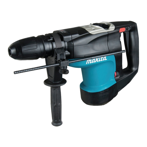
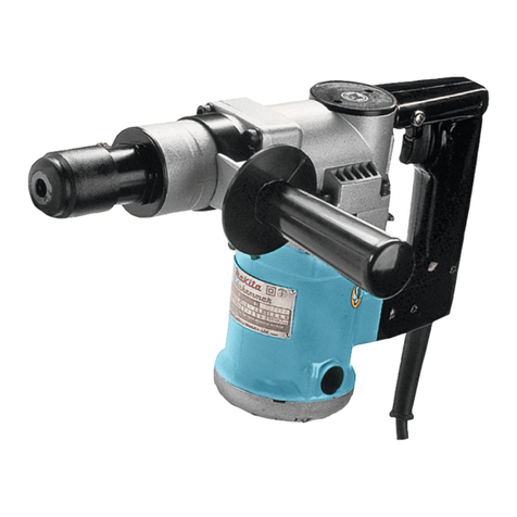
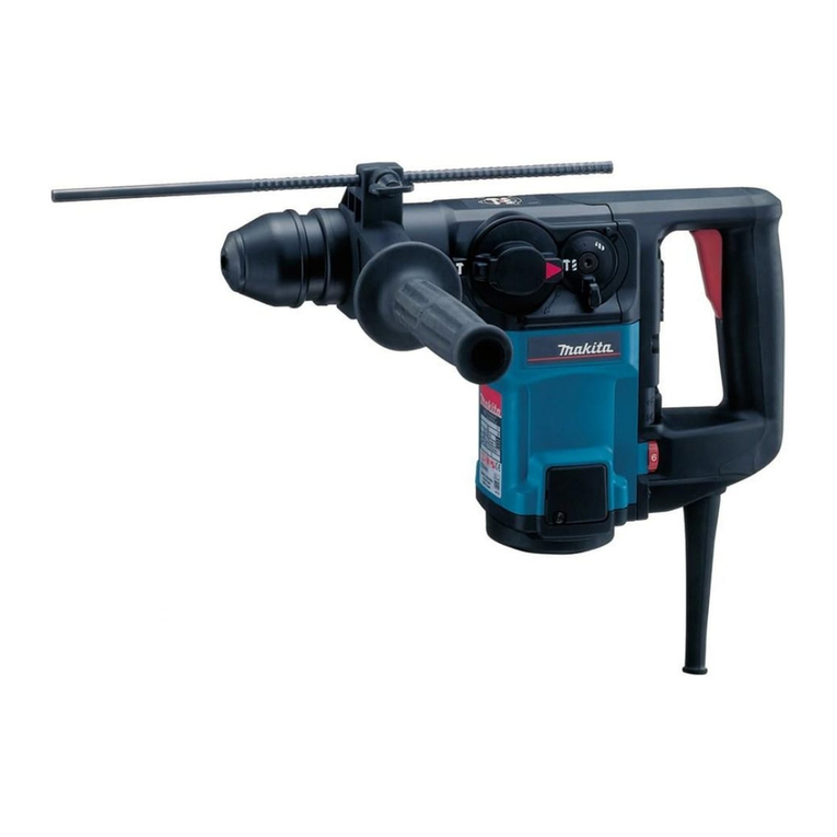
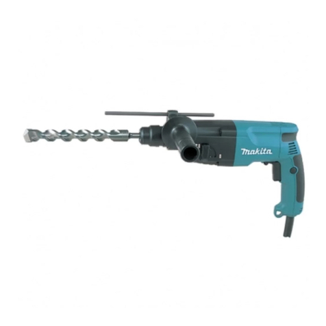
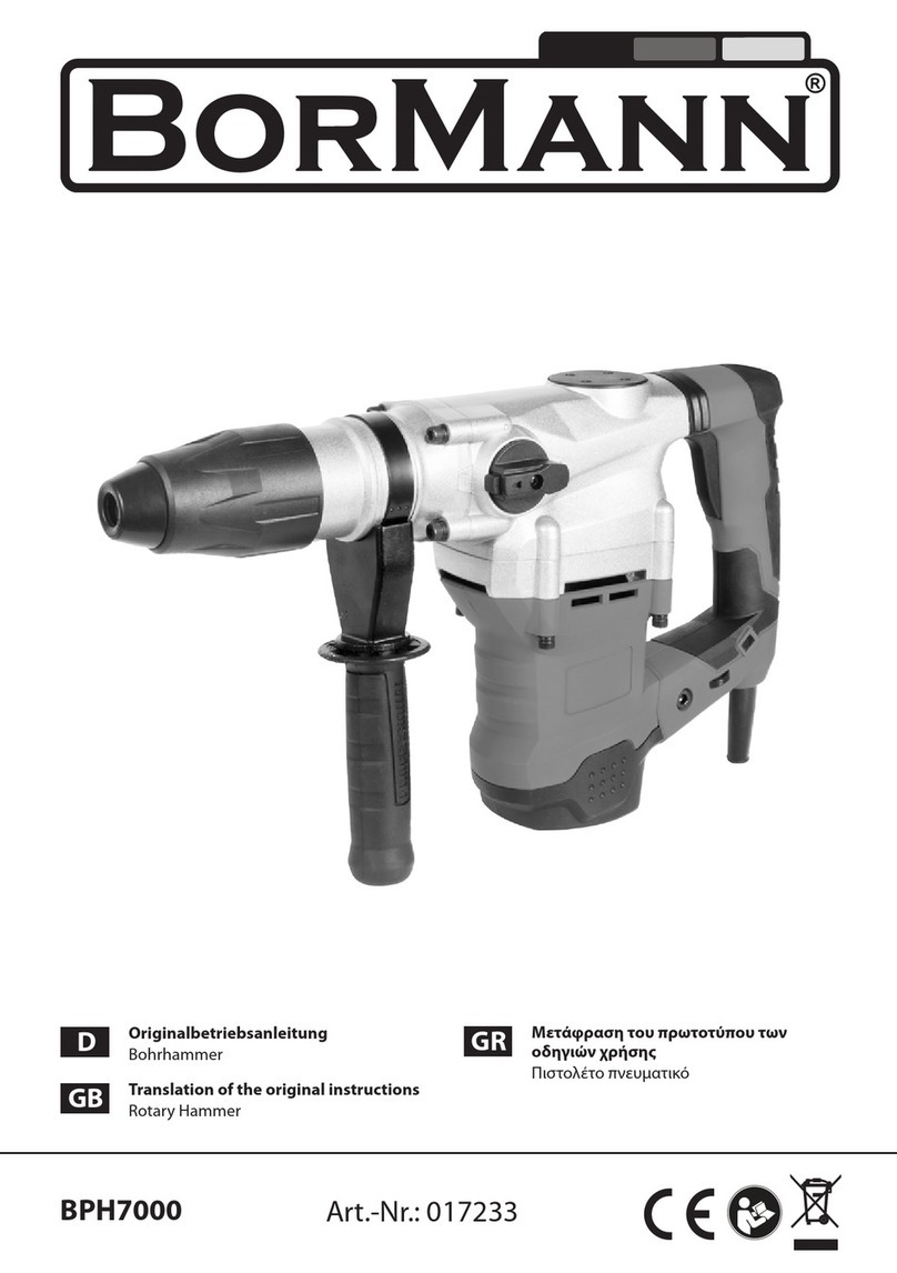
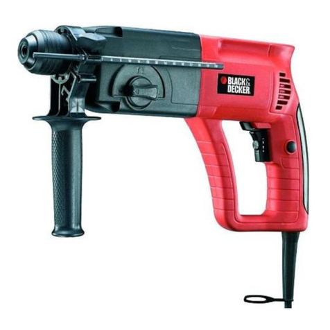
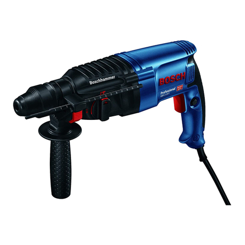
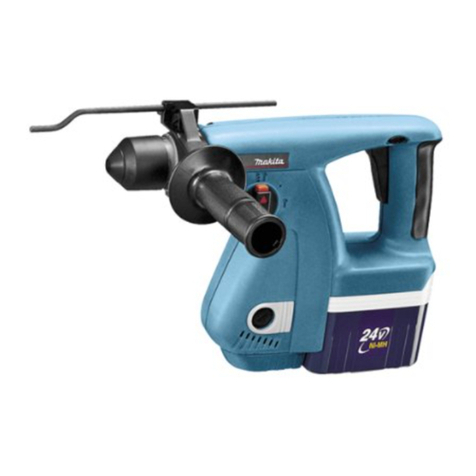
Makita HR140DSMJ User manual

HR140D
EN Cordless Rotary Hammer INSTRUCTION MANUAL 6
FR Perforateur Sans Fil MANUEL D’INSTRUCTIONS 12
DE Akku-Bohrhammer BETRIEBSANLEITUNG 18
IT Martello rotativo a batteria ISTRUZIONI PER L’USO 25
NL Accuboorhamer GEBRUIKSAANWIJZING 32
ES Martillo Rotativo Inalámbrico MANUAL DE
INSTRUCCIONES 38
PT Martelete Rotativo a Bateria MANUAL DE INSTRUÇÕES 45
DA Akku-borehammer BRUGSANVISNING 51
EL Φορητό σφυροτρύπανο ΕΓΧΕΙΡΙΔΙΟ ΟΔΗΓΙΩΝ 57
TR Akülü Kırıcı Delici KULLANMA KILAVUZU 64

1
2
3
Fig.1
1
2
Fig.2
1
Fig.3
1
2
Fig.4
1
AB
Fig.5
1
Fig.6
1
Fig.7
1
Fig.8
2

1
2
Fig.9
1
Fig.10
1
2
Fig.11
1
2
Fig.12
1
Fig.13
1
2
3
1
2
3
3
Fig.14
1
2
Fig.15
3

Fig.16
1
Fig.17
1
2
Fig.18
1
Fig.19
1
2
Fig.20
1
Fig.21
4

1
Fig.22
Fig.23
1
2
3
1
2
3
Fig.24
Fig.25
1
2
Fig.26
Fig.27
5

6ENGLISH
ENGLISH (Original instructions)
SPECIFICATIONS
Model: HR140D
Drilling capacities Concrete 14 mm
Steel 10 mm
Wood 13 mm
No load speed 0 - 850 min-1
Blows per minute 0 - 4,900 min-1
Overall length 246 mm
Rated voltage D.C. 10.8 V - 12 V max
Standard battery cartridge BL1015 / BL1016 / BL1020B / BL1021B / BL1040B / BL1041B
Net weight 1.9 - 2.6 kg
• Duetoourcontinuingprogramofresearchanddevelopment,thespecicationshereinaresubjecttochange
without notice.
• Specicationsandbatterycartridgemaydifferfromcountrytocountry.
• Theweightmaydifferdependingontheattachment(s),includingthebatterycartridge.Thelightestandheavi-
estcombination,accordingtoEPTA-Procedure01/2014,areshowninthetable.
Intended use
Thetoolisintendedforhammerdrillinganddrillingin
brick, concrete and stone.
Itisalsosuitablefordrillingwithoutimpactinwood,
metal, ceramic and plastic.
Noise
ThetypicalA-weightednoiseleveldeterminedaccord-
ing to EN60745:
Soundpressurelevel(LpA):84dB(A)
Soundpowerlevel(LWA):95dB(A)
Uncertainty(K):3dB(A)
WARNING: Wear ear protection.
Vibration
Thevibrationtotalvalue(tri-axialvectorsum)deter-
mined according to EN60745:
Work mode: hammer drilling into concrete
Vibrationemission(ah, HD):6.5m/s2
Uncertainty(K):1.5m/s2
Work mode: drilling into metal
Vibrationemission(ah,D):3.0m/s2or less
Uncertainty(K):1.5m/s2
NOTE:Thedeclaredvibrationemissionvaluehas
been measured in accordance with the standard test
methodandmaybeusedforcomparingonetoolwith
another.
NOTE:Thedeclaredvibrationemissionvalue
mayalsobeusedinapreliminaryassessmentof
exposure.
WARNING:Thevibrationemissionduringactual
useofthepowertoolcandifferfromthedeclared
emission value depending on the ways in which the
tool is used.
WARNING:Besuretoidentifysafetymeasures
to protect the operator that are based on an estima-
tionofexposureintheactualconditionsofuse(taking
accountofallpartsoftheoperatingcyclesuchas
thetimeswhenthetoolisswitchedoffandwhenitis
runningidleinadditiontothetriggertime).
EC Declaration of Conformity
For European countries only
TheECdeclarationofconformityisincludedasAnnexA
to this instruction manual.
SAFETY WARNINGS
General power tool safety warnings
WARNING: Read all safety warnings, instruc-
tions, illustrations and specications provided
with this power tool.Failuretofollowallinstructions
listedbelowmayresultinelectricshock,reand/or
seriousinjury.
Save all warnings and instruc-
tions for future reference.
Theterm"powertool"inthewarningsreferstoyour
mains-operated(corded)powertoolorbattery-operated
(cordless)powertool.

7ENGLISH
CORDLESS ROTARY HAMMER
SAFETY WARNINGS
1. Wear ear protectors. Exposure to noise can
cause hearing loss.
2. Use auxiliary handle(s), if supplied with the
tool.Lossofcontrolcancausepersonalinjury.
3.
Hold power tool by insulated gripping surfaces, when
performing an operation where the cutting accessory
may contact hidden wiring. Cutting accessory contacting
a"live"wiremaymakeexposedmetalpartsofthepower
tool"live"andcouldgivetheoperatoranelectricshock.
4.
Wear a hard hat (safety helmet), safety glasses and/
or face shield. Ordinary eye or sun glasses are NOT
safety glasses. It is also highly recommended that
you wear a dust mask and thickly padded gloves.
5.
Be sure the bit is secured in place before operation.
6.
Under normal operation, the tool is designed to
produce vibration. The screws can come loose
easily, causing a breakdown or accident. Check
tightness of screws carefully before operation.
7. In cold weather or when the tool has not been
used for a long time, let the tool warm up for
a while by operating it under no load. This
will loosen up the lubrication. Without proper
warm-up, hammering operation is difcult.
8.
Always be sure you have a rm footing. Be sure no
one is below when using the tool in high locations.
9. Hold the tool rmly with both hands.
10. Keep hands away from moving parts.
11. Do not leave the tool running. Operate the tool
only when hand-held.
12. Do not point the tool at any one in the area
when operating. The bit could y out and
injure someone seriously.
13.
Do not touch the bit, parts close to the bit, or
workpiece immediately after operation; they may
be extremely hot and could burn your skin.
14.
Some material contains chemicals which may be
toxic. Take caution to prevent dust inhalation and
skin contact. Follow material supplier safety data.
15.
Always be sure that the tool is switched off and
the battery cartridge and the bit are removed
before handing the tool to other person.
SAVE THESE INSTRUCTIONS.
WARNING:
DO NOT let comfort or familiarity with
product (gained from repeated use) replace strict adher-
ence to safety rules for the subject product. MISUSE or
failure to follow the safety rules stated in this instruc-
tion manual may cause serious personal injury.
Important safety instructions for
battery cartridge
1.
Before using battery cartridge, read all instruc-
tions and cautionary markings on (1) battery
charger, (2) battery, and (3) product using battery.
2. Do not disassemble battery cartridge.
3. If operating time has become excessively
shorter, stop operating immediately. It may
result in a risk of overheating, possible burns
and even an explosion.
4. If electrolyte gets into your eyes, rinse them
out with clear water and seek medical atten-
tion right away. It may result in loss of your
eyesight.
5. Do not short the battery cartridge:
(1) Do not touch the terminals with any con-
ductive material.
(2) Avoid storing battery cartridge in a con-
tainer with other metal objects such as
nails, coins, etc.
(3) Do not expose battery cartridge to water
or rain.
A battery short can cause a large current
ow, overheating, possible burns and even a
breakdown.
6. Do not store the tool and battery cartridge in
locations where the temperature may reach or
exceed 50 °C (122 °F).
7. Do not incinerate the battery cartridge even if
it is severely damaged or is completely worn
out. The battery cartridge can explode in a re.
8. Be careful not to drop or strike battery.
9. Do not use a damaged battery.
10.
The contained lithium-ion batteries are subject to
the Dangerous Goods Legislation requirements.
For commercial transports e.g. by third parties,
forwardingagents,specialrequirementonpack-
aging and labeling must be observed.
Forpreparationoftheitembeingshipped,consult-
inganexpertforhazardousmaterialisrequired.
Please also observe possibly more detailed
national regulations.
Tapeormaskoffopencontactsandpackupthe
battery in such a manner that it cannot move
around in the packaging.
11. Follow your local regulations relating to dis-
posal of battery.
12. Use the batteries only with the products
specied by Makita. Installing the batteries to
non-compliantproductsmayresultinare,exces-
siveheat,explosion,orleakofelectrolyte.
SAVE THESE INSTRUCTIONS.
CAUTION: Only use genuine Makita batteries.
Useofnon-genuineMakitabatteries,orbatteriesthat
have been altered, may result in the battery bursting
causingres,personalinjuryanddamage.Itwill
alsovoidtheMakitawarrantyfortheMakitatooland
charger.
Tips for maintaining maximum
battery life
1. Charge the battery cartridge before completely
discharged. Always stop tool operation and
charge the battery cartridge when you notice
less tool power.
2. Never recharge a fully charged battery car-
tridge. Overcharging shortens the battery
service life.
3. Charge the battery cartridge with room tem-
perature at 10 °C - 40 °C (50 °F - 104 °F). Let
a hot battery cartridge cool down before
charging it.

8ENGLISH
FUNCTIONAL
DESCRIPTION
CAUTION: Always be sure that the tool is
switched off and the battery cartridge is removed
before adjusting or checking function on the tool.
Installing or removing battery
cartridge
CAUTION: Always switch off the tool before
installing or removing of the battery cartridge.
CAUTION: Hold the tool and the battery car-
tridge rmly when installing or removing battery
cartridge. Failure to hold the tool and the battery
cartridgermlymaycausethemtoslipoffyourhands
and result in damage to the tool and battery cartridge
andapersonalinjury.
►Fig.1: 1. Red indicator 2. Button 3. Battery cartridge
Toremovethebatterycartridge,slideitfromthetool
whileslidingthebuttononthefrontofthecartridge.
Toinstallthebatterycartridge,alignthetongueonthe
battery cartridge with the groove in the housing and slip
it into place. Insert it all the way until it locks in place
withalittleclick.Ifyoucanseetheredindicatoronthe
uppersideofthebutton,itisnotlockedcompletely.
CAUTION: Always install the battery cartridge
fully until the red indicator cannot be seen.Ifnot,
itmayaccidentallyfalloutofthetool,causinginjuryto
you or someone around you.
CAUTION: Do not install the battery cartridge
forcibly.Ifthecartridgedoesnotslideineasily,itis
not being inserted correctly.
Battery protection system
Thetoolisequippedwithabatteryprotectionsystem.
Thissystemautomaticallycutsoffpowertothemotorto
extendbatterylife.
Thetoolwillautomaticallystopduringoperationifthe
tooland/orbatteryareplacedunderoneofthefollowing
conditions:
Overloaded:
Thetoolisoperatedinamannerthatcausesittodraw
an abnormally high current.
Inthissituation,turnthetooloffandstoptheapplication
thatcausedthetooltobecomeoverloaded.Thenturn
the tool on to restart.
Ifthetooldoesnotstart,thebatteryisoverheated.In
thissituation,letthebatterycoolbeforeturningthetool
on again.
Low battery voltage:
Theremainingbatterycapacityistoolowandthetool
willnotoperate.Ifyouturnthetoolon,themotorruns
again but stops soon. In this situation, remove and
recharge the battery.
Indicating the remaining battery
capacity
Only for battery cartridges with the indicator
►Fig.2: 1. Indicator lamps 2. Check button
Press the check button on the battery cartridge to indi-
catetheremainingbatterycapacity.Theindicatorlamps
lightupforafewseconds.
Indicator lamps Remaining
capacity
Lighted Off
75% to 100%
50% to 75%
25% to 50%
0% to 25%
NOTE:Dependingontheconditionsofuseandthe
ambienttemperature,theindicationmaydifferslightly
fromtheactualcapacity.
Switch action
WARNING: Before installing the battery car-
tridge into the tool, always check to see that the
switch trigger actuates properly and returns to
the "OFF" position when released.
►Fig.3: 1. Switch trigger
Tostartthetool,simplypulltheswitchtrigger.Tool
speed is increased by increasing pressure on the switch
trigger. Release the switch trigger to stop.
Lighting up the front lamp
►Fig.4: 1. Switch trigger 2. Lamp
CAUTION: Do not look in the light or see the
source of light directly.
Pulltheswitchtriggertolightupthelamp.Thelamp
keeps on lighting while the switch trigger is being pulled.
Thelampgoesoutapproximately10secondsafter
releasing the switch trigger.
NOTE:Useadryclothtowipethedirtoffthelensof
thelamp.Becarefulnottoscratchthelensoflamp,or
it may lower the illumination.

9ENGLISH
Reversing switch action
►Fig.5: 1. Reversing switch lever
CAUTION: Always check the direction of
rotation before operation.
CAUTION:
Use the reversing switch only after
the tool comes to a complete stop. Changing the direc-
tionofrotationbeforethetoolstopsmaydamagethetool.
CAUTION:
When not operating the tool, always
set the reversing switch lever to the neutral position.
Thistoolhasareversingswitchtochangethedirection
ofrotation.Depressthereversingswitchleverfromthe
AsideforclockwiserotationorfromtheBsideforcoun-
terclockwise rotation.
When the reversing switch lever is in the neutral posi-
tion, the switch trigger cannot be pulled.
Selecting the action mode
NOTICE: Do not rotate the action mode chang-
ing knob when the tool is running.Thetoolwillbe
damaged.
NOTICE: To avoid rapid wear on the mode
change mechanism, be sure that the action mode
changing knob is always positively located in one
of the action mode positions.
Rotation with hammering
For drilling in concrete, masonry, etc., rotate the action
mode changing knob to the symbol. Use a car-
bide-tipped drill bit.
►Fig.6: 1.Actionmodechangingknob
Rotation only
For drilling in wood, metal or plastic materials, rotate
the action mode changing knob to the symbol. Use a
twist drill bit or wood drill bit.
►Fig.7: 1.Actionmodechangingknob
ASSEMBLY
CAUTION: Always be sure that the tool is
switched off and the battery cartridge is removed
before carrying out any work on the tool.

Side grip (auxiliary handle)
CAUTION: Always use the side grip to ensure
safe operation.
CAUTION: After installing or adjusting the
side grip, make sure that the side grip is rmly
secured.
Installthesidegripsothatthegroovesonthegriptin
theprotrusionsonthetoolbarrel.Turnthegripclock-
wisetosecureit.Thegripcanbexedatdesiredangle.
►Fig.8: 1. Side grip
Grease
Coattheshankendofthedrillbitbeforehandwitha
smallamountofgrease(about0.5-1g).
Thischucklubricationassuressmoothactionandlongerservicelife.
Installing or removing drill bit
Cleantheshankendofthedrillbitandapplygrease
beforeinstallingthedrillbit.
►Fig.9: 1. Shank end 2. Grease
Insertthedrillbitintothetool.Turnthedrillbitandpush
it in until it engages.
Afterinstallingthedrillbit,alwaysmakesurethatthe
drill bit is securely held in place by trying to pull it out.
►Fig.10: 1. Drill bit
Toremovethedrillbit,pullthechuckcoverdownallthe
way and pull the drill bit out.
►Fig.11: 1. Drill bit 2. Chuck cover
Depth gauge
Thedepthgaugeisconvenientfordrillingholesofuniform
depth. Loosen the side grip and insert the depth gauge
intotheholeonthesidegrip.Adjustthedepthgaugeto
thedesireddepthandtightenthesidegriprmly.
►Fig.12: 1. Hole 2. Depth gauge
NOTE:Makesurethatthedepthgaugedoesnot
touchthemainbodyofthetoolwhenattachingit.
Dust cup
Optional accessory
Usethedustcuptopreventdustfromfallingoverthetooland
onyourselfwhenperformingoverheaddrillingoperations.
Attachthedustcuptothebitasshowninthegure.Thesize
ofbitswhichthedustcupcanbeattachedtoisasfollows.
Model Bit diameter
Dust cup 5 6 mm - 14.5 mm
Dust cup 9 12 mm - 16 mm
►Fig.13: 1. Dust cup
Dust cup set
Optional accessory
Installing the dust cup set
NOTICE:
If you purchase the dust cup set as optional
accessory, the standard side grip cannot be used with the
dust cup set being installed on the tool. When the dust cup
setisinstalledonthetool,removethegripfromthestandard
side grip, and then attach it to the optional grip base set.
►Fig.14: 1. Bolt 2. Grip 3. Optional grip base set
NOTICE: Do not use the dust cup set when drill-
ing in metal or similar. It may damage the dust cup
set due to the heat produced by small metal dust or
similar. Do not install or remove the dust cup set with
the drill bit installed in the tool. It may damage the
dust cup set and cause dust leak.

10 ENGLISH
Beforeinstallingthedustcupset,removethebitfrom
thetoolifinstalled.
1. Install the spacer so that the grooves on the
spacertintheprotrusionsonthetoolbarrelwhilewid-
eningit.Becarefulforthespringnottocomeofffrom
theslitofspacer.
►Fig.15: 1. Spacer 2. Spring
►Fig.16
2. Installthesidegrip(optionalgripbasesetand
thegripremovedfromstandardsidegrip)sothatthe
grooveonthegriptintheprotrusiononthespacer.
Turnthegripclockwisetosecureit.
►Fig.17: 1. Side grip
3. Installthedustcupsetsothattheclawsofthe
dustcuptinintheslitsonthespacer.
►Fig.18: 1. Dust cup 2. Claws
NOTE:Ifyouconnectavacuumcleanertothedust
cupset,removethedustcapbeforeconnectingit.
►Fig.19: 1. Dust cap
Removing the drill bit
Toremovethedrillbit,pullthechuckcoverdownallthe
way and pull the drill bit out.
►Fig.20: 1. Bit 2. Chuck cover
Removing the dust cup set
Toremovethedustcupset,followthestepsbelow.
1. Loosen the side grip.
►Fig.21: 1. Side grip
2. Holdtherootofdustcupandpullitout.
►Fig.22: 1. Dust cup
NOTE:Ifitisdifculttoremovethedustcupset,
removetheclawsofthedustcuponebyoneby
swingingandpullingtherootofthedustcup.
NOTE:Ifthecapcomesofffromthedustcup,attach
itwithitsprintedsidefacingupsothatgrooveonthe
captsintheinsideperipheryoftheattachment.
►Fig.23
Hook
Optional accessory
CAUTION:Alwaysremovethebatterywhen
hanging the tool with the hook.
CAUTION: Never hook the tool at high location
oronpotentiallyunstablesurface.
►Fig.24: 1. Groove 2. Hook 3. Screw
Thehookisconvenientfortemporarilyhangingthetool.
Thiscanbeinstalledoneithersideofthetool.
Toinstallthehook,insertitintoagrooveinthetool
housing on either side and then secure it with a screw.
Toremove,loosenthescrewandthentakeitout.
OPERATION
CAUTION: Always use the side grip (auxiliary
handle) and rmly hold the tool by both side grip
and switch handle during operations.
CAUTION: Always make sure that the work-
piece is secured before operation.
NOTE:Ifthebatterycartridgeisinlowtemperature,
thetool’scapabilitymaynotbefullyobtained.Inthis
case, warm up the battery cartridge by using the
toolwithnoloadforawhiletofullyobtainthetool’s
capability.
►Fig.25
Hammer drilling operation
CAUTION:Thereistremendousandsudden
twistingforceexertedonthetool/drillbitatthetimeof
hole break-through, when the hole becomes clogged
withchipsandparticles,orwhenstrikingreinforcing
rods embedded in the concrete. Always use the side
grip (auxiliary handle) and rmly hold the tool by
both side grip and switch handle during opera-
tions.Failuretodosomayresultinthelossofcontrol
ofthetoolandpotentiallysevereinjury.
Set the action mode changing knob to the symbol.
Positionthedrillbitatthedesiredlocationforthehole,
thenpulltheswitchtrigger.Donotforcethetool.Light
pressuregivesbestresults.Keepthetoolinposition
andpreventitfromslippingawayfromthehole.
Do not apply more pressure when the hole becomes
clogged with chips or particles. Instead, run the tool at
anidle,thenremovethedrillbitpartiallyfromthehole.
By repeating this several times, the hole will be cleaned
out and normal drilling may be resumed.
NOTE: Eccentricity in the drill bit rotation may occur
whileoperatingthetoolwithnoload.Thetoolauto-
maticallycentersitselfduringoperation.Thisdoesnot
affectthedrillingprecision.
Drilling in wood or metal
CAUTION: Hold the tool rmly and exert care
when the drill bit begins to break through the
workpiece.Thereisatremendousforceexertedon
thetool/drillbitatthetimeofholebreakthrough.
CAUTION: A stuck drill bit can be removed
simply by setting the reversing switch to reverse
rotation in order to back out. However, the tool
may back out abruptly if you do not hold it rmly.
CAUTION: Always secure workpieces in a
vise or similar hold-down device.

11 ENGLISH
NOTICE: Never use “rotation with hammering”
when the drill chuck is installed on the tool.The
drill chuck may be damaged.
Also,thedrillchuckwillcomeoffwhenreversingthetool.
NOTICE: Pressing excessively on the tool will
not speed up the drilling.Infact,thisexcessive
pressurewillonlyservetodamagethetipofyourdrill
bit,decreasethetoolperformanceandshortenthe
servicelifeofthetool.
Set the action mode changing knob to the symbol.
Attachthechuckadaptertoakeylessdrillchuckto
which1/2"-20sizescrewcanbeinstalled,andthen
installthemtothetool.Wheninstallingit,refertothe
section “Installing or removing drill bit”.
►Fig.26: 1. Drill chuck assembly 2. Chuck adapter
Blow-out bulb
Optional accessory
Afterdrillingthehole,usetheblow-outbulbtocleanthe
dustoutofthehole.
►Fig.27
MAINTENANCE
CAUTION: Always be sure that the tool is
switched off and the battery cartridge is removed
before attempting to perform inspection or
maintenance.
NOTICE: Never use gasoline, benzine, thinner,
alcohol or the like. Discoloration, deformation or
cracks may result.
TomaintainproductSAFETYandRELIABILITY,
repairs,anyothermaintenanceoradjustmentshould
beperformedbyMakitaAuthorizedorFactoryService
Centers,alwaysusingMakitareplacementparts.
OPTIONAL ACCESSORIES
CAUTION: These accessories or attachments
are recommended for use with your Makita tool
specied in this manual.Theuseofanyother
accessoriesorattachmentsmightpresentariskof
injurytopersons.Onlyuseaccessoryorattachment
foritsstatedpurpose.
Ifyouneedanyassistanceformoredetailsregard-
ingtheseaccessories,askyourlocalMakitaService
Center.
• Carbide-tippeddrillbits(SDS-Pluscarbide-tipped
bits)
• Chuckadapter
• Keylessdrillchuck
• Bitgrease
• Depthgauge
• Blow-outbulb
• Dustcup
• Dustcupset
• Gripbaseset
• Safetygoggles
• Hook
• Makitagenuinebatteryandcharger
• Plasticcarryingcase
NOTE: Some items in the list may be included in the
toolpackageasstandardaccessories.Theymay
differfromcountrytocountry.

12 FRANÇAIS
FRANÇAIS (Instructions originales)
SPÉCIFICATIONS
Modèle : HR140D
Capacités de perçage Béton 14 mm
Acier 10 mm
Bois 13 mm
Vitesse à vide 0 - 850 min-1
Frappes par minute 0 - 4 900 min-1
Longueur totale 246 mm
Tensionnominale 10,8 V - 12 V CC max.
Batterie standard BL1015 / BL1016 / BL1020B / BL1021B / BL1040B / BL1041B
Poids net 1,9 - 2,6 kg
• Étantdonnél’évolutionconstantedenotreprogrammederechercheetdedéveloppement,lesspécications
contenuesdanscemanuelsontsujettesàmodicationsanspréavis.
• Lesspécicationsetlabatteriepeuventêtredifférentessuivantlespays.
• Lepoidspeutêtredifférentselonlesaccessoires,notammentlabatterie.Lesassociationslapluslégèreetla
pluslourde,conformémentàlaprocédureEPTA01/2014,sontindiquéesdansletableau.
Utilisation prévue
L’outil est conçu pour le perçage avec martelage et le
perçagedanslabrique,lebétonetlapierre.
Il convient également au perçage sans impact dans le
bois,lemétal,lacéramiqueetleplastique.
Bruit
NiveaudebruitpondéréAtypique,déterminéselon
EN60745 :
Niveaudepressionsonore(LpA):84dB(A)
Niveaudepuissancesonore(LWA):95dB(A)
Incertitude(K):3dB(A)
AVERTISSEMENT : Portez un serre-tête
antibruit.
Vibrations
Valeurtotaledevibrations(sommedevecteurtriaxial)
déterminée selon EN60745 :
Modedetravail:perçageavecmartelagedanslebéton
Émissiondevibrations(ah, HD):6,5m/s2
Incertitude(K):1,5m/s2
Modedetravail:perçagedanslemétal
Émissiondevibrations(ah,D):3,0m/s2ou moins
Incertitude(K):1,5m/s2
NOTE : La valeur d’émission de vibrations déclarée
aétémesuréeconformémentàlaméthodedetest
standardetpeutêtreutiliséepourcomparerlesoutils
entre eux.
NOTE : La valeur d’émission de vibrations déclarée
peutaussiêtreutiliséepourl’évaluationpréliminaire
de l’exposition.
AVERTISSEMENT :
L’émission de vibrations lors de
l’usageréeldel’outilélectriquepeutêtredifférentedelavaleur
d’émissiondéclarée,suivantlafaçondontl’outilestutilisé.
AVERTISSEMENT : Les mesures de sécurité à
prendrepourprotégerl’utilisateurdoiventêtrebasées
sur une estimation de l’exposition dans des condi-
tionsréellesd’utilisation(entenantcomptedetoutes
les composantes du cycle d’utilisation, comme par
exemplelemomentdesamisehorstension,lorsqu’il
tourneàvideetlemomentdesondéclenchement).
Déclaration de conformité CE
Pour les pays européens uniquement
LadéclarationdeconformitéCEestfournieenAnnexe
Aàcemoded’emploi.
CONSIGNES DE SÉCURITÉ
Consignes de sécurité générales
pour outils électriques
AVERTISSEMENT : Veuillez lire les
consignes de sécurité, instructions, illustrations
et spécications qui accompagnent cet outil
électrique. Le non-respect de toutes les instructions
indiquéesci-dessouspeutentraîneruneélectrocu-
tion, un incendie et/ou de graves blessures.
Conservez toutes les mises en garde et
instructions pour référence ultérieure.
Leterme«outilélectrique»danslesavertissements
faitréférenceàl’outilélectriquealimentéparlesecteur
(aveccordond’alimentation)ouàl’outilélectriquefonc-
tionnantsurbatterie(sanscordond’alimentation).

13 FRANÇAIS
CONSIGNES DE SÉCURITÉ POUR
PERFORATEUR SANS FIL
1. Portez des protecteurs d’oreilles. L’exposition
aubruitpeutentraînerlasurdité.
2. Utilisez la ou les poignées auxiliaires, si l’outil
en possède.Toutepertedemaîtrisedel’outil
comporteunrisquedeblessure.
3.
Tenez l’outil électrique par des surfaces de prise
isolées lorsque vous effectuez une tâche au cours
de laquelle l’accessoire de coupe peut entrer en
contact avec des ls cachés. Le contact de l’acces-
soirededécoupeavecunlsoustensionpeuttrans-
mettreducourantdanslespiècesmétalliquesexpo-
séesdel’outilélectriqueetélectrocuterl’utilisateur.
4.
Portez un casque de sécurité (casque de chan-
tier), des lunettes de sécurité et/ou un écran
facial. Les lunettes de vue ou les lunettes de
soleil NE sont PAS des lunettes de sécurité. Il est
également vivement recommandé de porter un
masque anti-poussière et des gants matelassés.
5. Avant utilisation, assurez-vous que le foret est
bien xé en place.
6.
Dans des conditions normales de fonctionnement,
l’outil est conçu pour émettre des vibrations. Les
vis peuvent se desserrer facilement et provoquer
une panne ou un accident. Avant utilisation, véri-
ez soigneusement que les vis sont bien serrées.
7.
Par temps froid ou si l’outil n’a pas été utilisé
pendant longtemps, laissez-le chauffer un instant
en le faisant fonctionner à vide. Cela ramollira le
lubriant. Si vous ne chauffez pas adéquatement
l’outil, le martelage s’exécutera difcilement.
8.
Assurez-vous toujours de travailler en position
stable. Veillez à ce que personne ne se trouve en des-
sous de vous quand vous utilisez l’outil en hauteur.
9. Tenez l’outil fermement à deux mains.
10. Éloignez les mains des pièces en mouvement.
11.
Ne vous éloignez pas en laissant l’outil tourner. Ne le
faites fonctionner que lorsque vous l’avez bien en main.
12. Ne pointez l’outil vers personne dans la zone
d’utilisation. Le foret peut être projeté et bles-
ser gravement quelqu’un.
13.
Ne touchez pas le foret, les pièces proches du foret ou
la pièce immédiatement après l’exécution du travail ; ils
peuvent être extrêmement chauds et vous brûler la peau.
14. Certains matériaux contiennent des produits
chimiques qui peuvent être toxiques. Prenez
garde de ne pas avaler la poussière et évitez
tout contact avec la peau. Suivez les données
de sécurité du fournisseur du matériau.
15. Assurez-vous toujours que l’outil est hors
tension et que la batterie et le foret sont retirés
avant de passer l’outil à une autre personne.
CONSERVEZ CES INSTRUCTIONS.
AVERTISSEMENT :
NE vous laissez PAS tromper
(au l d’une utilisation répétée) par un sentiment d’aisance
et de familiarité avec le produit, en négligeant le respect
rigoureux des consignes de sécurité qui accompagnent le
produit en question. La MAUVAISE UTILISATION de l’outil
ou l’ignorance des consignes de sécurité indiquées dans
ce mode d’emploi peut entraîner de graves blessures.
Consignes de sécurité importantes
pour la batterie
1.
Avant d’utiliser la batterie, lisez toutes les instructions
et précautions relatives (1) au chargeur de batterie, (2)
à la batterie, et (3) au produit utilisant la batterie.
2. Ne démontez pas la batterie.
3. Cessez immédiatement l’utilisation si le temps
de fonctionnement devient excessivement
court. Il y a risque de surchauffe, de brûlures,
voire d’explosion.
4.
Si l’électrolyte pénètre dans vos yeux, rincez-les
à l’eau claire et consultez immédiatement un
médecin. Il y a risque de perte de la vue.
5. Ne court-circuitez pas la batterie :
(1) Ne touchez les bornes avec aucun maté-
riau conducteur.
(2) Évitez de ranger la batterie dans un
conteneur avec d’autres objets métal-
liques, par exemple des clous, des pièces
de monnaie, etc.
(3) N’exposez pas la batterie à l’eau ou à la
pluie.
Un court-circuit de la batterie peut provoquer
une intensité de courant élevée, une surchauffe,
parfois des brûlures et même une panne.
6.
Ne rangez pas l’outil et la batterie dans un endroit où la
température risque d’atteindre ou de dépasser 50 °C.
7.
Ne jetez pas la batterie au feu même si elle est
sérieusement endommagée ou complètement épui-
sée. La batterie peut exploser au contact du feu.
8.
Évitez de laisser tomber ou de cogner la batterie.
9.
N’utilisez pas la batterie si elle est endommagée.
10. Les batteries au lithium-ion contenues sont
soumises aux exigences de la législation sur
les marchandises dangereuses.
Lors du transport commercial par des tierces
parties ou des transitaires par exemple, des exi-
gencesspéciquesenmatièred’étiquetageet
d’emballagedoiventêtrerespectées.
Pour la préparation de l’article expédié, il est néces-
saire de consulter un expert en matériau dangereux.
Veuillezégalementrespecterlesréglementations
nationalessusceptiblesd’êtreplusdétaillées.
Recouvrezlescontactsexposésavecduruban
adhésifoudurubandemasquageetemballezla
batteriedetellesortequ’ellenepuissepasbouger
dans l’emballage.
11. Suivez les réglementations locales en matière
de mise au rebut des batteries.
12. Utilisez les batteries uniquement avec les
produits spéciés par Makita. L’insertion de
batteriesdansdesproduitsnonconformespeut
provoquerunincendie,unechaleurexcessive,
uneexplosionouunefuitedel’électrolyte.
CONSERVEZ CES INSTRUCTIONS.
ATTENTION :
N’utilisez que des batteries Makita
d’origine.L’utilisationdebatteriesdemarqueautreque
Makitaoudebatteriesmodiéespeutprovoquerl’explo-
siondesbatteries,cequiprésenteunrisqued’incendie,
de dommages matériels et corporels. Cela annulera égale-
mentlagarantieMakitapourl’outiletlechargeurMakita.

14 FRANÇAIS
Conseils pour assurer la durée
de vie optimale de la batterie
1. Chargez la batterie avant qu’elle ne soit com-
plètement déchargée. Arrêtez toujours l’outil
et rechargez la batterie quand vous remarquez
que la puissance de l’outil diminue.
2. Ne rechargez jamais une batterie complète-
ment chargée. La surcharge réduit la durée de
service de la batterie.
3.
Chargez la batterie à une température ambiante
comprise entre 10 °C et 40 °C. Avant de charger
une batterie chaude, laissez-la refroidir.
DESCRIPTION DU
FONCTIONNEMENT
ATTENTION : Assurez-vous toujours que
l’outil est hors tension et que sa batterie est
retirée avant de l’ajuster ou de vérier son
fonctionnement.
Insertion ou retrait de la batterie
ATTENTION : Éteignez toujours l’outil avant
de mettre en place ou de retirer la batterie.
ATTENTION : Tenez fermement l’outil et la
batterie lors de la mise en place ou du retrait de
la batterie.Sivousnetenezpasfermementl’outil
et la batterie, ils peuvent vous glisser des mains, et
s’abîmerouvousblesser.
►Fig.1: 1. Voyant rouge 2. Bouton 3. Batterie
Pourretirerlabatterie,faites-laglisserhorsdel’outil
toutenfaisantglisserleboutonàl’avantdelabatterie.
Pourmettreenplacelabatterie,alignezlalanguettesur
la batterie avec la rainure sur le compartiment et insé-
rez-la.Insérez-laàfondjusqu’àcequ’unlégerdéclic
sefasseentendre.Silevoyantrougesurledessusdu
boutonestvisible,celasigniequ’ellen’estpasbien
verrouillée.
ATTENTION : Insérez toujours complètement
la batterie jusqu’à ce que le voyant rouge ne soit
plus visible. Sinon, elle pourrait tomber acciden-
tellementdel’outil,aurisquedevousblesseroude
blesserquelqu’unsetrouvantprèsdevous.
ATTENTION : N’insérez pas la batterie de
force.Sielleneglissepasfacilement,c’estquevous
nel’insérezpascorrectement.
Système de protection de la batterie
L’outilestéquipéd’unsystèmedeprotectiondela
batterie.Cesystèmecoupeautomatiquementlecou-
rant de l’outil pour prolonger la durée de service de la
batterie.
L’outils’arrêteraautomatiquementencoursd’utilisation
si l’outil et/ou la batterie se trouve dans l’une ou l’autre
des situations suivantes :
Surcharge :
L’outilestutilisédemanièretellequ’ilconsommeun
courant anormalement élevé.
Danscecas,éteignezl’outiletarrêtezlatâcheayant
provoquélasurchargedel’outil.Puisrallumezl’outil
pourreprendrelatâche.
Sil’outilnedémarrepas,c’estquelabatterieasur-
chauffé.Danscecas,laissezlabatterierefroidiravant
de rallumer l’outil.
Faible tension de la batterie :
Lachargerestantedelabatterieesttropfaibleetl’outil
nefonctionnepas.Sivousmettezl’outilsoustension,
lemoteurredémarre,maiss’arrêterapidement.Lecas
échéant,retirezetrechargezlabatterie.
Indication de la charge restante de
la batterie
Uniquement pour les batteries avec voyant
lumineux
►Fig.2: 1.Témoins2.Boutondevérication
Appuyezsurleboutondevéricationsurlabatterie
pourindiquerlachargerestantedelabatterie.Les
témoinss’allumentpendantquelquessecondes.
Témoins Charge
restante
Allumé Éteint
75 % à 100 %
50 % à 75 %
25 % à 50 %
0 % à 25 %
NOTE : Selon les conditions d’utilisation et la tem-
pératureambiante,l’indicationpeutêtrelégèrement
différentedelacapacitéréelle.
Fonctionnement de la gâchette
AVERTISSEMENT : Avant d’insérer la batte-
rie dans l’outil, vériez toujours que la gâchette
fonctionne bien et revient en position d’arrêt
lorsque vous la relâchez.
►Fig.3: 1.Gâchette
Ilsuftd’enclencherlagâchettepourdémarrerl’outil.Lavitesse
del’outilaugmenteàmesurequel’onaccroîtlapressionexercée
surlagâchette.Pourl’arrêter,relâchezlagâchette.
Allumage de la lampe avant
►Fig.4: 1.Gâchette2. Lampe
ATTENTION : Évitez de regarder directement
le faisceau lumineux ou sa source.
Enclenchezlagâchettepourallumerlalampe.La
lamperestealluméetantquelagâchetteestenclen-
chée.Lalampes’éteintenviron10secondesaprès
avoirrelâchélagâchette.

15 FRANÇAIS
NOTE :Retirezlasaletésurlalentilledelalampe
avecunchiffonsec.Prenezsoindenepaséraer
la lentille de la lampe sous peine de diminuer son
éclairage.
Fonctionnement de l’inverseur
►Fig.5: 1. Levier de l’inverseur
ATTENTION : Vériez toujours le sens de
rotation avant d’utiliser l’outil.
ATTENTION : N’utilisez l’inverseur qu’une
fois que l’outil est complètement arrêté. Si vous
changezlesensderotationavantl’arrêtdel’outil,
vousrisquezdel’endommager.
ATTENTION : Lorsque vous n’utilisez pas
l’outil, placez toujours le levier de l’inverseur en
position neutre.
L’outilpossèdeuninverseurquipermetdechanger
lesensderotation.Enfoncezlelevierdel’inverseur
ducôtéApourunerotationdanslesensdesaiguilles
d’une montre, ou du côté B pour une rotation dans le
sens inverse des aiguilles d’une montre.
Lagâchettenepeutpasêtreenclenchéelorsquele
levier de l’inverseur se trouve en position neutre.
Sélection du mode de
fonctionnement
REMARQUE : Ne tournez pas le bouton de
changement de mode pendant que l’outil fonc-
tionne. L’outil serait endommagé.
REMARQUE : Pour éviter que le mécanisme
de changement de mode ne s’use rapidement,
vous devez toujours vous assurer que le bou-
ton de changement de mode est placé avec
exactitude sur l’une des positions du mode de
fonctionnement.
Rotation avec martelage
Pour percer dans le béton, de la maçonnerie, etc.,
tournezleboutondechangementdemodejusqu’au
symbole .Utilisezunforetàpointedecarbure.
►Fig.6: 1. Bouton de changement de mode
Rotation uniquement
Pour percer dans le bois, le métal ou des matériaux en
plastique,tournezleboutondechangementdemode
jusqu’ausymbole .Utilisezunforethélicoïdalouà
bois.
►Fig.7: 1. Bouton de changement de mode
ASSEMBLAGE
ATTENTION : Assurez-vous toujours que
l’outil est hors tension et que sa batterie est reti-
rée avant d’effectuer toute tâche dessus.
Poignée latérale (poignée auxiliaire)
ATTENTION : Utilisez toujours la poignée
latérale pour garantir votre sécurité.
ATTENTION : Après avoir mis en place ou
réglé la poignée latérale, assurez-vous qu’elle est
solidement xée.
Installezlapoignéelatéraledesortequelesrainures
delapoignéepénètrentdanslespartiessaillantesdu
barilletdel’outil.Tournezlapoignéedanslesensdes
aiguilles d’une montre pour la serrer en place. La poi-
gnéepeutêtrexéeàl’anglesouhaité.
►Fig.8: 1. Poignée latérale
Graisse
Enduisezaupréalablel’extrémitédelatigeduforet
avecunepetitequantitédegraisse(environ0,5à1g).
Cettelubricationdumandringarantitunmouvement
uideetprolongeladuréedevieutile.
Pose ou retrait du foret
Nettoyezl’extrémitédelatigeduforetetappliquezde
lagraisseavantdeposerleforet.
►Fig.9: 1. Extrémité de la tige 2. Graisse
Insérezleforetdansl’outil.Tournezleforetetenfon-
cez-lejusqu’àcequ’ils’engage.
Aprèsavoirposéleforet,assurez-voustoujoursqu’ilest
solidement maintenu en place en essayant de le sortir.
►Fig.10: 1. Foret
Pourretirerleforet,tirezlecarterdumandrinàfond
verslebaspuisdégagezleforet.
►Fig.11: 1. Foret 2. Carter du mandrin
Jauge de profondeur
Lajaugedeprofondeurestutilepourpercerdestrousde
mêmeprofondeur.Desserrezlapoignéelatéraleetinsé-
rezlajaugedeprofondeurdansl’oricesurlapoignée
latérale.Réglezlajaugedeprofondeursurlaprofondeur
désiréeetserrezfermementlapoignéelatérale.
►Fig.12: 1.Orice2.Jaugedeprofondeur
NOTE :Assurez-vousquelajaugedeprofondeur
n’entre pas en contact avec le corps principal de
l’outillorsquevouslaxez.
Collecteur de poussières
Accessoire en option
Utilisezlecollecteurdepoussièrespouréviterquela
poussièrenetombesurl’outiletsurvous-mêmelorsque
vouspercezau-dessusdevotretête.Fixezlecollecteur
depoussièresauforetcommeillustrésurlagure.Le
collecteurdepoussièrespeutêtrexéauxforetsdes
tailles suivantes.
Modèle Diamètreduforet
Collecteurdepoussières5 6 mm à 14,5 mm
Collecteurdepoussières9 12 mm à 16 mm
►Fig.13: 1.Collecteurdepoussières

16 FRANÇAIS
Ensemble du collecteur de poussières
Accessoire en option
Installation de l’ensemble du
collecteur de poussières
REMARQUE : Si vous achetez l’ensemble du
collecteur de poussières en tant qu’accessoire
en option, la poignée latérale standard ne peut
pas être utilisée avec l’ensemble du collecteur de
poussières installé sur l’outil.Lorsquel’ensemble
ducollecteurdepoussièresestinstallésurl’outil,
retirezlapoignéedelapoignéelatéralestandard,
puisxez-lasurl’ensemblepoignéeenoption.
►Fig.14: 1. Boulon 2. Poignée 3. Ensemble poignée
en option
REMARQUE : N’utilisez pas l’ensemble du col-
lecteur de poussières lorsque vous percez dans
le métal ou un matériau similaire.Vousrisqueriez
d’endommager l’ensemble du collecteur de pous-
sièresenraisondelachaleurproduiteparlespetites
poussièresmétalliquesousimilaires.N’installezpas,
nineretirezl’ensembleducollecteurdepoussières
avecleforetinsérésurl’outil.Vousrisqueriezd’en-
dommagerl’ensembleducollecteurdepoussièreset
deprovoquerunefuitedelapoussière.
Avantd’installerl’ensembleducollecteurdepous-
sières,retirezleforetdel’outillecaséchéant.
1. Installezl’entretoisedesortequelesrainures
del’entretoisepénètrentdanslespartiessaillantes
dubarilletdel’outillorsquevousl’écartez.Prenez
gardequeleressortnesedétachepasdelafentede
l’entretoise.
►Fig.15: 1. Entretoise 2. Ressort
►Fig.16
2. Installezlapoignéelatérale(ensemblepoignée
en option et poignée retirée de la poignée latérale
standard)desortequelarainuredelapoignéepénètre
danslapartiesaillantedel’entretoise.Tournezlapoi-
gnée dans le sens des aiguilles d’une montre pour la
serrer en place.
►Fig.17: 1. Poignée latérale
3. Installezl’ensembleducollecteurdepoussières
desortequelesgriffesducollecteurdepoussières
pénètrentdanslesfentesdel’entretoise.
►Fig.18: 1.Collecteurdepoussières2.Griffes
NOTE :Sivousraccordezunaspirateuràl’ensemble
ducollecteurdepoussières,retirezlebouchonà
poussièreavantdeleraccorder.
►Fig.19: 1.Bouchonàpoussière
Retrait du foret
Pourretirerleforet,tirezlecarterdumandrinàfond
verslebaspuisdégagezleforet.
►Fig.20: 1. Foret 2. Carter du mandrin
Retrait de l’ensemble du collecteur
de poussières
Procédezcommeilestindiquéci-dessouspourretirer
l’ensembleducollecteurdepoussières.
1. Desserrezlapoignéelatérale.
►Fig.21: 1. Poignée latérale
2. Tenezlabaseducollecteurdepoussièreset
sortez-le.
►Fig.22: 1.Collecteurdepoussières
NOTE :S’ils’avèredifcilederetirerl’ensembledu
collecteurdepoussières,retirezlesgriffesducollec-
teurdepoussièresuneparuneenbalançantettirant
sa base.
NOTE : Si le bouchon se détache du collecteur de
poussières,xez-leaveclecôtéimprimétournévers
lehautdesortequelarainuresurlebouchons’insère
dans la périphérie interne de l’accessoire.
►Fig.23
Crochet
Accessoire en option
ATTENTION :Retireztoujourslabatterie
lorsquel’outilestsuspenduparsoncrochet.
ATTENTION :N’accrochezjamaisl’outilàun
endroit élevé ou potentiellement instable.
►Fig.24: 1. Rainure 2. Crochet 3. Vis
Lecrochetestpratiquepoursuspendreprovisoirement
l’outil. Il s’installe d’un côté comme de l’autre de l’outil.
Pourinstallerlecrochet,insérez-ledansunerai-
nure du carter de l’outil sur l’un des deux côtés, puis
xez-leavecunevis.Pourleretirer,desserrezlaviset
enlevez-le.
UTILISATION
ATTENTION : Utilisez toujours la poignée
latérale (poignée auxiliaire) et saisissez l’outil
fermement par la poignée latérale et la poignée
pistolet pendant l’utilisation.
ATTENTION : Avant l’utilisation, assu-
rez-vous toujours que la pièce est bien xée.
NOTE :Encasdefaibletempératuredelabatterie,
l’outilrisquedenepasfonctionneràsapleinecapa-
cité.Danscecas,chauffezlabatterieenutilisant
l’outil sans charge pendant un instant pour obtenir la
pleine capacité de l’outil.
►Fig.25

17 FRANÇAIS
Perçage avec percussion
ATTENTION :Unetrèsgrandeforcedetorsion
s’exercesoudainementsurl’outilouleforetlorsqu’il
émergesurlafaceopposée,lorsqueletrouestbou-
ché par des copeaux ou particules ou lors du contact
avec des armatures dans le béton. Utilisez toujours
la poignée latérale (poignée auxiliaire) et saisis-
sez l’outil fermement par la poignée latérale et la
poignée pistolet pendant l’utilisation. Si vous ne
suivezpascettedirective,vousrisquerezdeperdrela
maîtrisedel’outiletdevousblessergrièvement.
Réglezleboutondechangementdemodesurlesymbole .
Placezleforetàl’emplacementdésirépourpercerletrou,puis
enclenchezlagâchette.Neforcezpasl’outil.Vousobtiendrez
demeilleursrésultatsavecunelégèrepression.Gardezl’outil
enpositionetempêchez-ledeglisserhorsdutrou.
N’appliquezpasplusdepressionlorsqueletrouestbouché
pardescopeauxouparticules.Laissezplutôtl’outiltourner
auralentietretirezpartiellementleforetdutrou.Enrépé-
tantcetteopérationplusieursfois,letrousedéboucheraet
vouspourrezreprendreleperçagenormalement.
NOTE :Lorsquel’outilfonctionneàvide,ilsepeut
queleforettournedemanièreexcentrique.L’outilse
centreralui-mêmeautomatiquementlorsdel’utilisa-
tion avec charge. La précision du perçage n’est donc
pasaffectée.
Perçage dans le bois ou le métal
ATTENTION : Tenez l’outil fermement et
redoublez d’attention lorsque le foret commence
à sortir par la face opposée de la pièce.Unetrès
grandeforces’exercesurl’outil/foretlorsquecelui-ci
émergesurlafaceopposée.
ATTENTION : Un foret coincé peut être retiré
en réglant simplement l’inverseur sur la rotation
inverse pour faire marche arrière. L’outil peut tou-
tefois faire brusquement marche arrière si vous
ne le tenez pas fermement.
ATTENTION : Immobilisez toujours les pièces
à travailler dans un étau ou un dispositif de rete-
nue similaire.
REMARQUE :
N’utilisez jamais la « rotation avec
martelage » lorsque le mandrin à foret est installé sur
l’outil.Lemandrinàforetrisqueraitd’êtreendommagé.
Deplus,lemandrinàforetsedétacheraitlorsde
l’inversion de la rotation de l’outil.
REMARQUE : Une pression excessive sur l’outil
n’accélèrera pas le perçage.Enfait,lapression
excessiveabîmeralapointeduforet,provoqueraune
baisse de rendement de l’outil et réduira sa durée de
service.
Réglezleboutondechangementdemodesurlesymbole .
Fixezl’adaptateurdemandrinsurunmandrinàforet
sansclésurlequelpeutêtreinstalléeunevisdetype
1/2″-20,puisinstallez-lessurl’outil.Pourl’installer,
reportez-vousàlasection«Poseouretraitduforet».
►Fig.26: 1.Ensemblemandrinàforet2.Adaptateur
de mandrin
Poire soufante
Accessoire en option
Unefoisletroupercé,utilisezlapoiresoufantepour
enretirerlapoussière.
►Fig.27
ENTRETIEN
ATTENTION : Assurez-vous toujours que
l’outil est hors tension et que la batterie est reti-
rée avant d’y effectuer tout travail d’inspection ou
d’entretien.
REMARQUE : N’utilisez jamais d’essence, ben-
zine, diluant, alcool ou autre produit similaire.
Cela risquerait de provoquer la décoloration, la
déformation ou la ssuration de l’outil.
PourassurerlaSÉCURITÉetlaFIABILITÉduproduit,
toute réparation, tout travail d’entretien ou de réglage
doiventêtreeffectuésparuncentred’entretienMakita
agréé,avecdespiècesderechangeMakita.
ACCESSOIRES EN OPTION
ATTENTION : Ces accessoires ou pièces
complémentaires sont recommandés pour l’utili-
sation avec l’outil Makita spécié dans ce mode
d’emploi. L’utilisation de tout autre accessoire ou
piècecomplémentairepeutcomporterunrisquede
blessure.N’utilisezlesaccessoiresoupiècescomplé-
mentairesqu’auxnsauxquellesilsontétéconçus.
Pour obtenir plus de détails sur ces accessoires,
contactezvotrecentred’entretienlocalMakita.
• Foretsàpointedecarbure(foretsàpointede
carbureSDS-plus)
• Adaptateurdemandrin
• Mandrinàforetsansclé
• Graisseàforet
• Jaugedeprofondeur
• Poiresoufante
• Collecteurdepoussières
• Ensembleducollecteurdepoussières
• Ensemblepoignée
• Lunettesdesécurité
• Crochet
• BatterieetchargeurMakitad’origine
• Étuidetransportenplastique
NOTE :Ilsepeutquecertainsélémentsdelaliste
soient compris dans l’emballage de l’outil en tant
qu’accessoiresstandard.Ilspeuventvarierd’unpays
à l’autre.

18 DEUTSCH
DEUTSCH (Original-Anleitung)
TECHNISCHE DATEN
Modell: HR140D
Bohrkapazitäten Beton 14 mm
Stahl 10 mm
Holz 13 mm
Leerlaufdrehzahl 0 - 850 min-1
SchlagzahlproMinute 0 - 4.900 min-1
Gesamtlänge 246 mm
Nennspannung 10,8 V Gleichstrom - 12 V max.
Standard-Akku BL1015 / BL1016 / BL1020B / BL1021B / BL1040B / BL1041B
Nettogewicht 1,9 - 2,6 kg
• Wirbehaltenunsvor,ÄnderungendertechnischenDatenimZugederEntwicklungunddestechnischen
FortschrittsohnevorherigeAnkündigungvorzunehmen.
• DietechnischenDatenundderAkkukönnenvonLandzuLandunterschiedlichsein.
• DasGewichtkannabhängigvondemAufsatz(denAufsätzen),einschließlichdesAkkus,unterschiedlich
sein.DieleichtesteunddieschwersteKombination,gemäßdemEPTA-Verfahren01/2014,sindinderTabelle
angegeben.
Vorgesehene Verwendung
DasWerkzeugistfürHammerbohrenundBohrenin
Ziegeln,BetonundSteinvorgesehen.
EseignetsichauchfürnormalesBohreninHolz,Metall,
KeramikundKunststoff.
Geräusch
TypischerA-bewerteterGeräuschpegelermitteltgemäß
EN60745:
Schalldruckpegel(LpA):84dB(A)
Schallleistungspegel(LWA):95dB(A)
Messunsicherheit(K):3dB(A)
WARNUNG: Einen Gehörschutz tragen.
Schwingungen
Schwingungsgesamtwert(Drei-Achsen-Vektorsumme)
ermitteltgemäßEN60745:
Arbeitsmodus:HammerbohreninBeton
Schwingungsemission(ah, HD):6,5m/s2
Messunsicherheit(K):1,5m/s2
Arbeitsmodus:BohreninMetall
Schwingungsemission(ah,D):3,0m/s2oder weniger
Messunsicherheit(K):1,5m/s2
HINWEIS: Der angegebene
Schwingungsemissionswert wurde im Einklang mit
derStandardprüfmethodegemessenundkannfür
denVergleichzwischenWerkzeugenherangezogen
werden.
HINWEIS: Der angegebene
Schwingungsemissionswertkannauchfüreine
VorbewertungdesGefährdungsgradsverwendet
werden.
WARNUNG:DieSchwingungsemissionwährend
dertatsächlichenBenutzungdesWerkzeugskann
jenachderBenutzungsweisedesWerkzeugsvom
angegebenen Emissionswert abweichen.
WARNUNG:IdentizierenSie
SicherheitsmaßnahmenzumSchutzdesBenutzers
anhandeinerSchätzungdesGefährdungsgradsunter
dentatsächlichenBenutzungsbedingungen(unter
BerücksichtigungallerPhasendesArbeitszyklus,wie
z.B.Ausschalt-undLeerlaufzeitendesWerkzeugs
zusätzlichzurBetriebszeit).
EG-Konformitätserklärung
Nur für europäische Länder
DieEG-KonformitätserklärungistalsAnhangAindieser
Bedienungsanleitung enthalten.
SICHERHEITSWARNUNGEN
Allgemeine Sicherheitswarnungen
für Elektrowerkzeuge
WARNUNG: Lesen Sie alle mit die-
sem Elektrowerkzeug gelieferten
Sicherheitswarnungen, Anweisungen,
Abbildungen und technischen Daten durch. Eine
MissachtungderuntenaufgeführtenAnweisungen
kannzueinemelektrischenSchlag,Brandund/oder
schwerenVerletzungenführen.

19 DEUTSCH
Bewahren Sie alle Warnungen
und Anweisungen für spätere
Bezugnahme auf.
DerAusdruck„Elektrowerkzeug“indenWarnhinweisen
beziehtsichaufIhrmitNetzstrom(mitKabel)oderAkku
(ohneKabel)betriebenesElektrowerkzeug.
SICHERHEITSWARNUNGEN FÜR
AKKU-BOHRHAMMER
1. Tragen Sie Gehörschützer.Lärmeinwirkung
kannGehörschädigungverursachen.
2. Benutzen Sie (einen) Zusatzgriff(e), sofern er
(sie) mit dem Werkzeug geliefert wurde(n).
VerlustderKontrollekannPersonenschäden
verursachen.
3. Halten Sie das Elektrowerkzeug an den iso-
lierten Griffächen, wenn Sie Arbeiten aus-
führen, bei denen die Gefahr besteht, dass
das Schneidwerkzeug verborgene Kabel
kontaktiert.BeiKontaktmiteinemStromführen-
denKabelkönnendiefreiliegendenMetallteile
desElektrowerkzeugsebenfallsStromführend
werden,sodassderBenutzereinenelektrischen
Schlag erleiden kann.
4. Tragen Sie Schutzhelm, Schutzbrille und/
oder Gesichtsschutz. Eine gewöhnliche Brille
oder Sonnenbrille ist KEIN Ersatz für eine
Schutzbrille. Das Tragen einer Staubmaske
und dick gepolsterter Handschuhe ist eben-
falls zu empfehlen.
5. Vergewissern Sie sich vor der Arbeit, dass der
Einsatz sicher montiert ist.
6. Das Werkzeug erzeugt konstruktionsbedingt
Vibrationen bei normalem Betrieb. Durch
Lockerung von Schrauben kann es zu einem
Ausfall oder Unfall kommen. Unterziehen Sie
die Schrauben vor der Arbeit einer sorgfältigen
Festigkeitsprüfung.
7. Lassen Sie das Werkzeug bei niedri-
gen Temperaturen oder nach längerer
Nichtbenutzung eine Zeit lang im Leerlauf
warm laufen. Dadurch wird die Schmierung
verbessert. Betrieb im kalten Zustand
erschwert die Schlagbohrarbeit.
8. Achten Sie stets auf sicheren Stand.
Vergewissern Sie sich bei Einsatz des
Werkzeugs an hochgelegenen Arbeitsplätzen,
dass sich keine Personen darunter aufhalten.
9.
Halten Sie das Werkzeug mit beiden Händen fest.
10.
Halten Sie Ihre Hände von beweglichen Teilen fern.
11. Lassen Sie das Werkzeug nicht unbeaufsich-
tigt laufen. Benutzen Sie das Werkzeug nur mit
Handhaltung.
12. Richten Sie das Werkzeug während des
Betriebs nicht auf umstehende Personen. Der
Einsatz könnte herausschnellen und schwere
Verletzungen verursachen.
13. Vermeiden Sie eine Berührung des
Einsatzes, der umliegenden Teile oder des
Werkstücks unmittelbar nach der Bearbeitung,
weil die Teile noch sehr heiß sind und
Hautverbrennungen verursachen können.
14. Manche Materialien können giftige
Chemikalien enthalten. Treffen Sie
Vorsichtsmaßnahmen, um das Einatmen
von Arbeitsstaub und Hautkontakt zu verhü-
ten. Befolgen Sie die Sicherheitsdaten des
Materiallieferanten.
15. Vergewissern Sie sich stets, das Werkzeug
ausgeschaltet ist und der Akku und der
Einsatz abgenommen sind, bevor Sie das
Werkzeug einer anderen Person aushändigen.
DIESE ANWEISUNGEN
AUFBEWAHREN.
WARNUNG: Lassen Sie sich NICHT durch
Bequemlichkeit oder Vertrautheit mit dem Produkt
(durch wiederholten Gebrauch erworben) von
der strikten Einhaltung der Sicherheitsregeln für
das vorliegende Produkt abhalten. MISSBRAUCH
oder Missachtung der Sicherheitsvorschriften in
dieser Anleitung können schwere Verletzungen
verursachen.
Wichtige Sicherheitsanweisungen
für Akku
1. Lesen Sie vor der Benutzung des Akkus alle
Anweisungen und Warnhinweise, die an (1)
Ladegerät, (2) Akku und (3) Akkuwerkzeug
angebracht sind.
2. Unterlassen Sie ein Zerlegen des Akkus.
3. Falls die Betriebszeit beträchtlich kürzer
geworden ist, stellen Sie den Betrieb sofort
ein. Anderenfalls besteht die Gefahr von
Überhitzung, möglichen Verbrennungen und
sogar einer Explosion.
4. Falls Elektrolyt in Ihre Augen gelangt, waschen
Sie sie mit sauberem Wasser aus, und
begeben Sie sich unverzüglich in ärztliche
Behandlung. Anderenfalls können Sie Ihre
Sehkraft verlieren.
5. Der Akku darf nicht kurzgeschlossen werden:
(1) Die Kontakte dürfen nicht mit leitfähigem
Material berührt werden.
(2) Lagern Sie den Akku nicht in einem
Behälter zusammen mit anderen
Metallgegenständen, wie z. B. Nägel,
Münzen usw.
(3) Setzen Sie den Akku weder Wasser noch
Regen aus.
Ein Kurzschluss des Akkus verursacht star-
ken Stromuss, der Überhitzung, mögliche
Verbrennungen und einen Defekt zur Folge
haben kann.
6. Lagern Sie das Werkzeug und den Akku nicht
an Orten, an denen die Temperatur 50 °C errei-
chen oder überschreiten kann.
7. Versuchen Sie niemals, den Akku zu verbren-
nen, selbst wenn er stark beschädigt oder
vollkommen verbraucht ist. Der Akku kann im
Feuer explodieren.
8. Achten Sie darauf, dass der Akku nicht fallen
gelassen oder Stößen ausgesetzt wird.
9. Benutzen Sie keine beschädigten Akkus.

20 DEUTSCH
10. Die enthaltenen Lithium-Ionen-Akkus unter-
liegen den Anforderungen der Gefahrengut-
Gesetzgebung.
FürkommerzielleTransporte,z.B.durch
DritteoderSpediteure,müssenbesondere
AnforderungenzuVerpackungundEtikettierung
beachtet werden.
ZurVorbereitungdeszutransportierenden
ArtikelsisteineBeratungdurcheinenExpertenfür
Gefahrenguterforderlich.BittebeachtenSiemög-
licherweiseausführlicherenationaleVorschriften.
ÜberklebenoderverdeckenSieoffeneKontakte,
undverpackenSiedenAkkuso,dassersichin
der Verpackung nicht umher bewegen kann.
11. Befolgen Sie die örtlichen Bestimmungen
bezüglich der Entsorgung von Akkus.
12. Verwenden Sie die Akkus nur mit den von
Makita angegebenen Produkten.DasEinsetzen
derAkkusinnichtkonformeProduktekannzu
einemBrand,übermäßigerHitzebildung,einer
ExplosionoderAuslaufenvonElektrolytführen.
DIESE ANWEISUNGEN
AUFBEWAHREN.
VORSICHT: Verwenden Sie nur Original-
Makita-Akkus. Die Verwendung von Nicht-Original-
Makita-AkkusodervonAkkus,dieabgeändert
wordensind,kannzumBerstendesAkkusund
darausresultierendenBränden,Personenschäden
undBeschädigungführen.Außerdemwirddadurch
dieMakita-GarantiefürdasMakita-Werkzeugund
-Ladegerätungültig.
Hinweise zur Aufrechterhaltung
der maximalen
Akku-Nutzungsdauer
1. Laden Sie den Akku, bevor er vollkommen
erschöpft ist. Schalten Sie das Werkzeug stets
aus, und laden Sie den Akku, wenn Sie ein
Nachlassen der Werkzeugleistung feststellen.
2. Unterlassen Sie erneutes Laden eines voll
aufgeladenen Akkus. Überladen führt zu einer
Verkürzung der Nutzungsdauer des Akkus.
3. Laden Sie den Akku bei Raumtemperatur
zwischen 10 – 40 °C. Lassen Sie einen heißen
Akku abkühlen, bevor Sie ihn laden.
FUNKTIONSBESCHREIBUNG
VORSICHT: Vergewissern Sie sich vor
der Durchführung von Einstellungen oder
Funktionsprüfungen des Werkzeugs stets, dass
das Werkzeug ausgeschaltet und der Akku abge-
nommen ist.
Anbringen und Abnehmen des
Akkus
VORSICHT: Schalten Sie das Werkzeug
stets aus, bevor Sie den Akku anbringen oder
abnehmen.
VORSICHT: Halten Sie das Werkzeug und
den Akku beim Anbringen oder Abnehmen
des Akkus sicher fest.WennSiedasWerkzeug
unddenAkkunichtsicherfesthalten,können
sieIhnenausderHandrutschen,waszueiner
BeschädigungdesWerkzeugsunddesAkkusundzu
Körperverletzungenführenkann.
►Abb.1: 1.RoteAnzeige2.Knopf3.Akku
ZiehenSiedenAkkuzumAbnehmenvomWerkzeug
ab,währendSiedenKnopfanderVorderseitedes
Akkusverschieben.
RichtenSiezumAnbringendesAkkusdessen
FührungsfederaufdieNutimGehäuseaus,undschie-
benSiedenAkkuhinein.SchiebenSieihnvollständig
ein,bisermiteinemhörbarenKlickeneinrastet.Falls
dieroteAnzeigeanderOberseitedesKnopfessichtbar
ist,istderAkkunichtvollständigverriegelt.
VORSICHT: Schieben Sie den Akku stets bis
zum Anschlag ein, bis die rote Anzeige nicht mehr
sichtbar ist.AnderenfallskannerausdemWerkzeug
herausfallenundSieoderumstehendePersonen
verletzen.
VORSICHT: Unterlassen Sie
Gewaltanwendung beim Anbringen des Akkus.
FallsderAkkunichtreibungsloshineingleitet,ister
nicht richtig ausgerichtet.
Akku-Schutzsystem
DasWerkzeugistmiteinemAkku-Schutzsystemaus-
gestattet. Dieses System schaltet die Stromversorgung
desMotorsautomatischab,umdieAkku-Lebensdauer
zuverlängern.
DasWerkzeugschaltetsichwährenddesBetriebs
automatischab,wennWerkzeugund/oderAkkueiner
derfolgendenBedingungenunterliegen:
Überlastung:
DasWerkzeugwirdaufeineWeisebenutzt,dieeine
ungewöhnlichhoheStromaufnahmebewirkt.
SchaltenSieindieserSituationdasWerkzeugaus,
undbrechenSiedieArbeitab,dieeineÜberlastung
desWerkzeugsverursachthat.SchaltenSiedanndas
Werkzeugwiederein,umneuzustarten.
FallsdasWerkzeugnichtstartet,istderAkkuüberhitzt.
LassenSiedenAkkuindieserSituationabkühlen,
bevorSiedasWerkzeugwiedereinschalten.
This manual suits for next models
1
Table of contents
Languages:
Other Makita Rotary Hammer manuals

Makita
Makita HR2300 User manual

Makita
Makita HR2470 User manual

Makita
Makita HR4001C User manual

Makita
Makita HR4501C User manual

Makita
Makita HR3520B User manual

Makita
Makita HR1830 User manual

Makita
Makita HR2010 Quick start guide

Makita
Makita DHR165Z User manual

Makita
Makita HR2010 User manual

Makita
Makita HR1830 User manual

Makita
Makita HR2230X2 User manual

Makita
Makita HR4001C User manual

Makita
Makita HR5000 Quick start guide

Makita
Makita DHR171ZJ User manual

Makita
Makita HR3851 User manual

Makita
Makita HR4500C User manual

Makita
Makita M8700 User manual

Makita
Makita HR4511C User manual

Makita
Makita HR3000C User manual

Makita
Makita BHR200S Manual