Makita 2702X1 User manual

Table
Saw
210
mm
(8-114") MODEL 2702x1 255
mm
(10") MODEL 2703x1
210
mm
(8-114") MODEL 2702 255
mm
(10") MODEL 2703
With Electric Brake With Electric Brake
MODEL
2702x1
2702
2703x1
2703
INSTRUCTION
MANUAL
y;,;r
E6k&dier
Cut""g
Capac't'eS Table size No load speed Dimensions Net
900 450
1w
x
ti
IRPMI
It
x
W
x
HI
weight
210mm
68mm,,
47"
18~114") 12~11116
I
11~3/4"1
255
mm
91
mm
63"
IlO'I
13-9116"1 12 112")
686
mm
x
560
mm
4,600
560 mm
x
686
mm
x
458
mm
18
kg
(27"
x
22") (22"
x
27"
x
18") 140
Ibsl
518"
DOUBLE
INSULATION
Note: Specifications may differ from country to country.
WARNING: For your personal safety, READ and UNDERSTAND before using.
SAVE THESE INSTRUCTIONS
FOR
FUTURE REFERENCE.

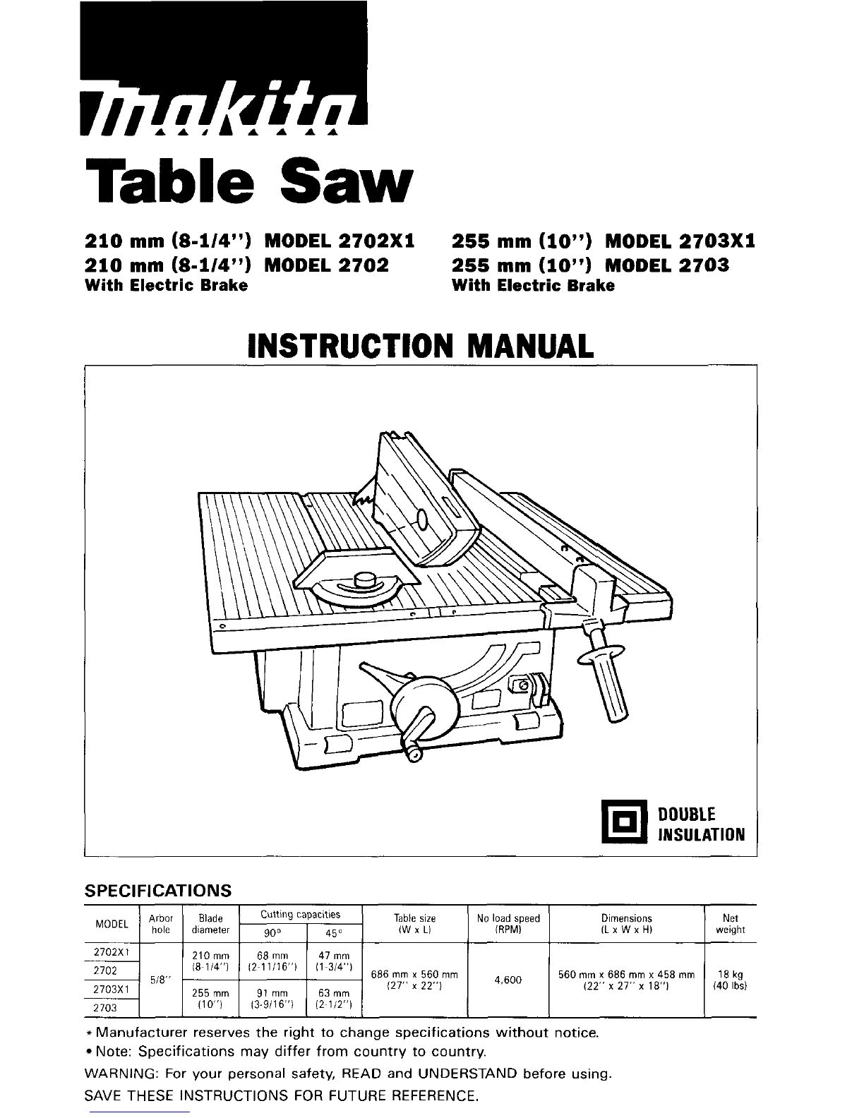
For Your Own Safety Read Instruction Manual
Before Operating Table Saw
Save
it
for future reference
GENERAL SAFETY PRECAUTIONS
(For
All
Tools)
1.
KNOWYOUR POWER TOOL. Readtheowner’s manualcarefully. Learnthetool’s
applicationsand limitations, as wellas the specific potentialhazards peculiarto
it.
2.
KEEP GUARDS IN PLACE and in working order.
3.
REMOVE ADJUSTING KEYS AND WRENCHES. Form habit of checking to see
that keys and adjusting wrenches are removed from tool before turning
it
on.
4.
KEEP WORK AREA CLEAN. Cluttered areas and benches invite accidents.
5.
DON’T USE IN DANGEROUSENVIRONMENT. Don’t use power tools in damp
or wet locations, or expose them to rain. Keep work area well lighted.
Don’t use tool
in
presence of flammable liquids or gases.
6.
KEEP CHILDRENAWAY. Allvisitorsshould bekeptsafedistancefromwork area.
7.
MAKE WORKSHOP CHILD PROOF
with
padlocks, master switches, or by
removing starter keys.
8.
DON’T FORCE TOOL.
It
will
do the job better and safer at the rate for which
it
was designed.
9.
USE RIGHT TOOL. Don’t force tool or attachment to do a job for which
it
was
notdesigned; for example, don’t use circular saw for cuttingtree limbs or logs.
IO.
WEAR PROPER APPAREL. Wear no loose clothing, gloves, neckties, rings,
bracelets, or other jewelry which may get caught
in
moving parts. Nonslip
footwear is recommended. Wear protective hair covering to contain long hair.
1 1.
ALWAYS USESAFETY GLASSES. Also useface or dust mask if cuttingoperation
is dusty. Everydayeyeglasses
only
have impact resistant lenses, they are NOT
safety glasses.
12.
SECURE WORK. Use clamDs or a vise to hold work when Dractical. It’s safer
13.
14.
15.
16.
17.
18.
2
than using your hand and
it
frees both hands to operate tool.
DON’T OVERREACH. Keep proper footing and balance at all times.
MAINTAINTOOLS WITH CARE. Keep tools sharp and cleanfor best and safest
performance. Follow instructions for lubricating and changing accessories.
DISCONNECT TOOLS before servicing; when changing accessories such as
blades, bits, cutters, and the like.
REDUCETHE RISK OF UNINTENTIONALSTARTING. Make sure switch is
in
off
position before plugging
in.
USE RECOMMENDEDACCESSORIES. Consult the owner‘s manual for recom-
mended accessories. The use of improper accessories may cause risk of injury
to persons.
NEVER STAND ON TOOL. Serious injury could occur if the tool is tipped or
if
the cutting
tool
is accidentally contacted.

19.
CHECK DAMAGEDPARTS. Before further use of the tool, a guard or other part
that is damaged should be carefully checked to determine that
it
will
operate
properlyandperformitsintendedfunction
-
checkfor alignment
of
movingparts,
binding of moving parts, breakageof parts, mounting, and any other conditions
that may affect itsoperation. A guard or other part that isdamaged should be
properly repaired or replaced.
20.
DIRECTIONOF FEED. Feed work into a blade or cutter against the direction of
rotation of the blade or cutter only.
21.
NEVER LEAVETOOL RUNNINGUNATTENDED. TURN POWER
OFF.
Don't leave
tool until
it
comes to a complete stop.
22.
When servicing use only identical replacement parts.
23.
POLARIZEDPLUGS. To reduce the risk of electric shock, this equipment has a
polarizedplug(onebladeiswider thantheother). This plug
will
fit ina polarized
outlet only one way. Ifthe plug does notfit fully
in
the outlet, reversethe plug.
If
it
still does not fit, contact a qualified electrician to install the proper outlet.
Do not change the plug
in
any way.
Ampere Rating
Not
More Than More Than
0
6
6 10
10 12
12 16
VOLTAGE WARNING: Beforeconnectingthetool
to
apower source(receptacle, outlet,
etc.) be sure the voltage supplied is the same as that specified on the nameplate
of the tool. A power source
with
voltage greater thanthat specified for the tool can
result
in
SERIOUS INJURY tothe user
-
as well as damage tothe tool. If indoubt,
DO NOT PLUG
IN
THE TOOL. Using a power source
with
voltage less than the
nameplate rating is harmful to the motor.
Volts
I
Total length of cord in feet
120V
1
25ft.
50
ft.
100
ft.
150
ft.
AWG
18 16 16 14
18 16 14 12
16 16 14 12
14 12
Not Recommended
EXTENSIONCORDS. Makesureyour extensioncord is
in
goodcondition. When using
anextensioncord, besuretouseone heavyenough tocarrythecurrent your product
will
draw. An undersized cord
will
cause a drop
in
line voltage resulting
in
loss
of
power and overheating. Table
1
shows the correct size to use depending on cord
lengthandnameplateampere rating. Ifindoubt, usethe nextheaviergage. Thesmaller
the gage number, the heavier the cord.
Minimum aaae for cord
3

ADDITIONAL SAFETY
RULES
1.
Wear eye protection.
2.
Don't use the tool
in
presence of flammable liquids or gases.
3.
Never use the tool with an abrasive cut-off wheel installed.
4.
Check the blade carefully for cracks or damage before operation. Replace
cracked or damaged blade immediately.
5. Clean the spindle, flanges (especially the installing surface) and hex nut
before installing the blade. Poor installation may cause vibrationlwobbling
or slippage of the blade.
6.
Use saw-blade guard and spreader for every operation for which
it
can be
used, including
all
through sawing operations. Through sawing operations
are those in which the blade cuts completely through the workpiece as
in
rippingor crosscutting. Never use the tool
with
afaulty bladeguardor secure
theblade guard
with
a rope, string, etc. Any irregular operation of the blade
guard should be corrected immediately.
7.
Donot cut metalssuch as nails and screws. Inspectfor and removeall nails,
screws and other foreign matter from the workpiece before operation.
8.
Remove wrenches, cut-off pieces, etc. from the table before the switch is
turned on.
9.
Never wear gloves during operation.
IO.
Keep hands outof the line of saw blade. Do not stand or permit anyone else
to stand
in
line with the path of the saw blade.
11.
Makesure the blade isnot contacting the spreader or workpiece beforethe
switch is turned on.
12.
Before cutting an actual workpiece, let the tool run for a while. Watch for
vibration or wobbling that could indicate poor installation
or
a poorlybalanced
blade.
13.
Usea pushstick when required. Pushsticksshouldbeusedfor ripping narrow
workpieces to keep your hands and fingers well away from the blade.
14.
Pay particular attention to instructions for reducing risk of KICKBACK.
KICKBACK is the ejection of the workpiece from the tool back towards the
operator. Avoid KICKBACKS by keeping the blade sharp,
by
keeping the rip
fence paralleltothe blade, by keepingthe spreader, antikickback fingersand
bladeguard in place and operating properly, by not releasing the workpiece
until you have pushed
it
all the way past the blade, and by not ripping a
workpiece
that
istwisted or warped or does not have a straightedge toguide
along the fence.
15. Do not perform any operation freehand. Freehandmeans using your hands
to support or guide the workpiece.
16.
Never reach around or over saw blade.
4

17.
Avoid abrupt, fast feeding. Feed as slowly as possible when cutting hard
workpieces.
Do
not bend or twist workpiece while feeding. If you stall or
jam the blade in the workpiece, turn the tool off immediately. Unplug the
tool. Then clear the jam.
18.
Never remove cut-off pieces near the blade or touch the blade guard while
the blade is running.
19.
Don't abuse cord. Neveryank cordtodisconnect from receptacle. Keep cord
away from heat, oil, water and sharp edges.
SAVE THESE INSTRUCTIONS.
5

ASSEMBLY
The tool isshipped from the factory with the saw blade and bladeguard not in the installed
condition.Assemble as follows:
CAUTl
ON:
Always unplug the tool before assembly.
Installing saw blade
Removethe table insert on the table. Hold
the outer flange with the offset wrench
and loosen the hex nut with the wrench.
Then removethe outer flange.
Assemble the inner flange, blade, outer
flange and hex nut onto the arbor, making
sure that theteeth
of
the bladeare pointing
down at the front of the table. Always
install the hex nut with its recessed side
facing the outer flange.
CAUTION:
Keep the flange surface clean of dirt or
other adhering matter;it could cause blade
slippage. Be sure that the blade
is
installed
so
that the teeth are aligned in the cutting
(turning)direction.
To secure the blade in place, holdthe outer
flange with the offset wrench, thentighten
the hex nutwith the wrench. BE SURE TO
TIGHTEN
THE
HEX NUT SECURELY.
CAUTION:
Be sure to hold the hex nut carefully with
the wrench. If
your
grip should slip, the
wrench may come off the hex nut, and
your hand could strike the sharp blade
edges.
Offset wrench
J
\
-
Wrench
Hex nut
Inner
B
flange
Outer flange
Hex nut
Saw
blade
6

installing bladeguard
CAUTION:
Before installing the bladeguard, adjust the depth of cut to its maximum elevation.
Insert the spreader between the blade
guard mounting portion (stay)and the pres-
sure plate.
7
guard
Tighten the hex bolts (A) with the offset
wrench. The spreader installing location is
factory-adjusted
so
that the blade and
spreader will be in
a
straight line. However,
if they are not in
a
straight line. loosen the
hex bolts
(B)
and adjust the blade guard
mounting portion(stay)
so
that the spreader
is aligned directly behind the blade. Then
tighten the hex bolts
(B)
to secure the stay.
-
Spreader
Pressureplate
These twoclearances
'lade
7
h
should be equal
Bladeguard
portion
Spreader
Pressureplate Hex
bolts
(A)
Hex bolts
(6)
CAUTION:
*Always grasp the striped portion of the offset wrench when tightening the hex bolts. If
you tighten the hex bolts while grasping the offset wrench further than the striped por-
tion, the hex bolts may be damagedand/or an injury toyour handmay result.
If the blade and spreader are not aligned properly,
a
dangerous pinching condition may
result during operation. Make sure they are properly aligned.
There must be a clearance
of
about
4
-
5 mm(5/32"
-
13/64") betweenthe spread-
Spreader
7
er and the blade teeth. Adjust the spreader
accordingly and tighten the hex bolts
(A)
securely. Attach the table insert on the
table, then check to see that the blade
guardworks smooth.
(5/32"
-
13/64")
7

Locate the table saw in
a
well lit and level
area where you can maintain good footing
and balance. It should be installed in an
area that leaves enough room to easily
handle the size of your workpieces. The
table saw should be secured with four
screws or boltsto the work bench or table
saw stand using the holes provided in the
bottom of the table saw. When securing
the table saw on the work bench, make
sure that there is an opening in the top of
the work benchthe same size as the open-
6 mm (1/4")
-
Std. washer
25 mm (1")
459 mm
(18-1/16")
334
mm Hole diameter
(13-1/8")
8
mm(5/16")
No.
10wood screw
40 mm (1-1/2")min. length
6 mm (1/4")
Std. washer
6 mm (1/4") Machinebolt
&
nut tighten securely
If during operation there is any tendency for the table saw to tip over, slide or move, the
work bench or table saw stand should be securedto the floor.
NOTE: Table saw stand
Models
2702x1
and
2703x1
are standard-equippedwith
a
table saw stand.
Storing accessory
The mitergauge and wrenches can be stored on the left side of the base and the ripfence
can be storedat the rear of the base
Miter
I
8

Adjusting depth
of
cut
The depth of cut may be adjusted by turn-
ing the handle. Turn the handle clockwise
to raise the blade or counterclockwise to
lower it.
NOTE:
Use a shallow depth setting when cutting
thin materials in order to obtain
a
cleaner
cut.
Adjusting bevel angle
Loosen the lock lever and turn the hand-
wheel until the desired angle
(0"
-
45") is
obtained. The bevel angle is indicated by
the arrow pointer. After obtaining the
desired angle, tighten the lock lever to
secure the adjustment.
CAUTION:
After adjusting the bevel, besure totighten
the lock lever securely.
L
I
I
II
LowYer Raise
I
Handle
I
TRr
Lock lever
Handwheel
/L,,,,
pointer
Adjusting positive stops
The tool is equipped with positivestops
at
90"
and45" to the table surface.
To
check and
adjust the positive stops, proceedas follows:
Move the handwheel as far as possible by turning it. Place a triangular rule on the table
and check
to
see if the blade is
at
90"
or 45" to the table surface. If the blade
is
at
an
angle shown in Fig. A, turn the adjusting screws clockwise; if it isat an angle shown in
Fig.
B,
turnthe adjusting screwscounterclockwise toadjust the positivestops.
90"
adjusting screw
45"
adjusting screw
9

After adjusting the positive stops, set the
blade at
90"
to the table surface. Then
adjust the arrow pointer
so
that its right
edge is alignedto the
0"
graduation.
Installing and adjustingripfence
Raise the grip of the rip fence. Install the
rip fence on the table
so
that the fence
holder engages with the guide rail. The rip
fence can be secured by loweringthe grip.
To check to be sure that the rip fence is
parallelwith the blade, secure the ripfence
2
-
3
mm
(5/64"
-
1/8")
from the blade.
Raise the blade up to maximumelevation.
Mark one of the blade teeth with
a
crayon.
Measure the distance
(A)
and
(B)
between
the rip fence and blade. Take both
measurements using the tooth marked
with the crayon. These two measurements
should be identical.
If
the rip fence is not
parallelwith the blade, proceedas follows:
1.
Turn the adjusting nut counterclockwise
2.
Loosen the two hex bolts on the rip
3.
Adjust the rip fence until
it
becomes
4.
Lowerthe grip to secure the ripfence.
5.
Tighten the two hex bolts on the rip
a
coupleof turns.
fence with the wrench provided.
parallelwiththe blade.
fence.
Guide rail Grip
Scale
I
..
d
Hex
bolts
nut
-
Grip
I! I
10

CAUTION:
I
~ Scale plate
3
I
Arrow mark
Always grasp the striped portion
of
the
wrench when tighteningthe hex bolts. If
you tighten the hex bolts while grasping
the wrench further than the striped por-
tion, the hex bolts may be damaged
and/or an injury toyour handmay result.
6.
With the grip of the rip fence lowered, turn the adjusting nut clockwise to secure the
rear end of the rip fence.
Do
not turn the adjusting nut clockwise excessively. You may
have some difficulty adjusting the rip fence parallel with the saw blade when re-
positioning the ripfence.
CAUTION:
Besure to adjust the ripfence parallelwith the blade, or adangerouskickback condition
mayoccur.
Bring the ripfence upflush againstthe side
of the blade. Make sure that the arrow
pointeron the fence holder points to the
0"
graduation. If the arrow pointer does not
pointto the
0"
graduation, loosenthe screw
on the scale plate and adjust the scale
plate.
Switch
action
This tool is equipped with a special type of
switch to prevent unintentional starting.
TO
startthe tool, first depressthe switch lever.
While keeping
it
depressed, pull its lower
portiontoward you.
To
stop the tool, press
the lower portionof the switch lever.
Screw
7
I
4-
Fence
holder
Ylkl
-I
Swltchlever
lo1
Key
-
11

When operating the switch lever, it is con-
venient to view itthrough the window area
inthe table.
LI
llllll
CAUTION
:
*When not using the tool, remove the key and store it in
a
secure place. This prevents
Before plugging in the tool, always check to see that the switch lever actuates properly
Do
notpullthe switch lever hardwithout the key.This can cause breakageof the switch.
unauthorizedoperation.
and returns to the “OFF“ position.
OPERATION
CAUTION:
*Always use ”work helpers” such as push sticks and push blockswhen there is
a
danger
that your hands or fingers
will
come closeto the blade.
*Always holdthe workpiecefirmly.
Do
notbendor twist
it
while feeding.
If
theworkpiece
is bent or twisted, dangerous kickbacks may occur.
*Never withdraw the workpiece while the blade is running. If you must withdraw the
workpiecebeforecompleting
a
cut, first switch the tool off while holding the workpiece
firmly. Wait until the blade has come to
a
completestop beforewithdrawing the work-
piece. Failureto do
so
may cause dangerous kickbacks.
Never removecut-off materialwhile the bladeis running.
Never placeyour hands
or
fingers inthe pathof the saw blade. Be especially carefulwith
Always secure the ripfence firmly, or dangerous kickbacks may occur.
*Always use “work helpers” such as push sticks and push blocks when cutting small or
bevelcuts.
narrowworkpieces, or when the dado head is hiddenfrom view while cutting.
Work
helpers
Push sticks, push blocksor auxiliary fence are types of “work helpers”. Usethem to make
safe, sure cuts without the needfor the operator to contact the blade with any part of the
body.
12

Push stick
A
push stick can be easily madefrom apiece of plywood 19"
(3/4")
to 25" (1
'7
thick.
Make auxiliary fence from 9.5 mm
(3/8")
and 19mm
(3/4")
plywoodpieces.
Cut out the hatched area on the stick and smooth edges witha file.
(HI
dimension should
be less than
12.7
mm(1/2")
so
as to be thinner than the workpiece.
40
mm
9.5
mm
140
mm
parallel (1
8")
(5.112")
Push block
Usea 19mm
(3/4")
piece of plywood.
I
,
300
mm
(12")
,
1
n
(1/2")
Handle should be in center of plywood piece. Fasten with glue and wood screws as
shown. Small piece9.5 mm
x
8
mm
x
50 mm
(3
/8"
x
5/16"
x
2")
of woodmust always be
glued to plywood to keep the blade from dulling if the operator cuts into push block by
mistake. (Neveruse nails in push block.)
Auxiliary
fence
I
Fasten with glue andwood screws.
13

Wood
facing (rbfence)
I
A wood facing should be used for opera-
tions when the blade comes close to the
rip fence. Wood facing for the rip fence
should be same size as the ripfence. Make
sure the bottom
of
facing is flush with the
table surface.
No.
10
wood screws
(longenough to penetr:
halfway intofacing)
Crosscutting
CAUTION:
When making
a
crosscut, removethe ripfence from the table.
When cutting long or large workpieces, always provideadequate support to the sides of
the table. The support should be at the same height as the table.
Miter gauge
Usethe mitergauge for the
4
types of cuttingshownbelow
ni
I
CROSS
CUTTING MITERING BEVEL CUTTING COMPOUND MITERING (ANGLES1
CAUTION
:
Securethe knob on the mitergauge carefully.
*Avoid creep of workpiece and gauge by firm workholding arrangement, especially when
cutting
at
an angle.
14

Use
of
miter gauge
Slidethe miter-gaugeinto the thick grooves
in the table. Loosenthe knob on the gauge
and align to desiredangle
(0"
to
60").
Bring
stock flush up against fence and feed
gently forwardintothe blade.
Auxiliary
wood
facing
(miter
gauge)
To
prevent
a
long board from wobbling, fit
the miter gauge with an auxiliary fence
board. Fasten with boltshuts after drilling
holes, but fasteners must not protrude
from theface board.
Ripping
CAUTIO
N
:
When ripping, removethe mitergauge from the table.
*When cutting long or large workpieces, always provide adequate support behind the
table. The support should be
at
the same height as the table.
Before operating the table saw, check to be sure that the antikickback fingers operate
properly.Turn the tool off and unplug it. Feed the workpiece under the blade guard and
along both sides of the blade
to
simulate cutting.Try to withdraw the workpiece on each
side by pulling
it
towardyou. The antikickbackfingers should grab the workpiece and pre-
vent itfrom movingback towardthe operator.Always keepthe antikickbackfingers sharp
so
they will operate properly.Keep them sharp by using round-shaped
file
to maintainthe
original shape of the fingers.
15

1. Adjust the depthof cut
a
bit higher than
the thicknessof the workpiece.
2. Position the rip fence to the desired
width
of
rip and lock in place by lower-
ing the grip. Before ripping, make sure
the rear end of the rip fence is secured
firmly.
If
it is notsecuredenough, follow
the proceduresin "Installing and adjust-
ing rip fence" describedon page 10and
11.
3.
Turn the
tool
on and gently feedthe workpiece into the blade alongwith the rip fence.
i)
When thewidth of rip is 150mm (6")
and wider, carefully use your right
hand to feed the workpiece. Use
your left hand to hold the workpiece
in positionagainst the rip fence.
ii)
When the width of rip is 65 mm
-
r
iii)
When the width
of
rip is narrower
than 65 mm (2-1/2"), the push stick
cannot be used because the push
stick will strike the blade guard. Use
the auxiliaw fence and push block.
Attach the auxiliary fence
to
the rip
fence with two
"C"
clamps.
16

Feedthe workpiece
by
hand untilthe
end is about
25
mm
(1”)
from the
front edge
of
the table. Continue to
feed using the push block on the top
of the auxiliary fence until the cut is
complete.
7
Push
block
Auxilian/
fence
17

MAINTENANCE
CAUTION:
Always be sure that the tool is switchedoff and unpluggedbefore attemptingto perform
inspectionor maintenance.
Cleaning
Clean out sawdust and chips from time to time. Carefully clean the blade guard and mov-
ingparts insidethe table saw.
Lubrication
To
keepthe table saw intip-toprunningcondition, and to assure maximumservice life, oil
or grease the moving partsand rotatingpartsfrom time to time.
Lubricationplaces:
Threaded shaft to elevate the blade
Hingeto rotate the frame
Elevationguide shafts on motor
Gear to elevate the blade
Replacingcarbon brushes
Remove and check the carbon brushes
regularly. Replacewhen they wear down to
the limit mark. Keep the carbon brushes
clean and free to slip in the holders. Both
carbon brushes should be replaced at the
same time. Use only identical carbon
brushes.
-
Use
a
holder cap opener to remove the
brush holder caps.
To
replace the carbon
brush in the side near the table, lower the
blade as far as possible by turning the
handle. Loosen the lock lever, tilt the blade
and secure
it
at
45".
Then loosenthe brush
holder cap while viewing
it
through the
opening the base. Remove the worn car-
bon brushes, insert the new ones and
secure the brush holder caps.
Holder cap opener
To maintain product SAFETY and RELIABILITY,repairs, any other maintenanceor adjust-
ment shouldbe performedby MakitaAuthorizedor Factory Service Centers, always using
Makita replacementparts.
18

ACCESSORIES
CAUTION
:
These accessories or attachments are recommendedfor use with your Makitatool speci-
fied inthis manual. The use of any other accessories or attachments might present
a
risk
of
injuryto persons.The accessoriesor attachments should be usedonly in the proper and
intended manner.
Dado head set
Part
NO.
1915434)
A
dado is cutting
a
rabbet or
a
wide groove
into the workpiece.The dado head set con-
sists
of
two outside cutters, three inside
cuttersand paper washers.
1
1/8"
118"
1/16"
1/8"
1/8"
Outside cutters
:
6" diameter, 118'' thick,
Insidecutters
:
6" diameter, 118'' thick,
I
518" arbor hole, 2pcs.
518" arbor hole, 2PCS.
Insidecutter
Paper washers
:
518'' arbor hole, 6 pcs.
:
6" diameter, 1/16" thick, 518'' arbor hole, 1pc.
Various combinations
of
these cuttersare used to cut grooves from 118'' to 112'' for use in
makingjoints, tenoning, grooving, etc.
Dadoflange set
(Part
No.
192693-8)
Dadoouter flange
When cuttinggroove 1/4", 5/16", 3/8", 7/16" or 112".
use this dado outer flange.
Dadohex nut
When cuttinggroove 1/4", 5/16", 3/8", 7/16" or 1/2",
use this dado hex nut.
Ring
When cuttinggroove 1/4", 5/16", 318". 7/16" or 1/2",
use this ring.
Washer
When cuttinggroove 1/4", 5/16" or 318".
use this washer.
19

Table
insert
(Part
No.
31
7060-8
for
Model
2702)
(Part
No.
317061-6
for
Model
2703)
When cutting grooves
511
6",
3/8",
7/16"
or
112''
use this table insert instead of the
standardtable insert.
L
711
6"
112"
9x2
CAUTION:
For
a
1/8"
cut width, the outside cutter
is
assembledto the spindle inthe same manner
.The outer flange or the dado outer flange must be used for each cutwidth.
The hex nut alone must not be usedto secure the dado on to the spindle.
as
the saw blade.
20
Other manuals for 2702X1
3
This manual suits for next models
3
Table of contents
Other Makita Saw manuals

Makita
Makita 5704R User manual

Makita
Makita 5104 User manual

Makita
Makita DSP600ZJ User manual

Makita
Makita LS002G User manual

Makita
Makita LS1440 User manual

Makita
Makita LH1200FL User manual

Makita
Makita MLS100 User manual

Makita
Makita 2704 User manual

Makita
Makita DPB181 User manual

Makita
Makita LS1017 User manual

Makita
Makita DLS600 User manual

Makita
Makita LS0714 Manual

Makita
Makita JR3050T User manual

Makita
Makita MLT100 User manual

Makita
Makita SR1800 User manual

Makita
Makita DLS610 User manual

Makita
Makita SP6000 User manual

Makita
Makita HS7611 User manual

Makita
Makita LS1440 User manual

Makita
Makita HS7611J User manual