Makita LS1040 User manual

GB
Compound Miter Saw Instruction Manual
F
Scie à coupe d’onglet mixte Manuel d’instructions
D
Gehrungs- und Kappsäge Betriebsanleitung
I
Sega a quartabuono composta Istruzioni per l’uso
NL
Gecombineerde verstekzaag Gebruiksaanwijzing
E
Sierra de inglete mixta Manual de instrucciones
P
Serra de esquadria composta Manual de instruções
DK
Afkorter-geringssav Brugsanvisning
S
Kap- och gerings kombinationssåg Bruksanvisning
N
Kompound gjæringssag Bruksanvisning
SF
Yhdistetty jiirisaha Käyttöohje
GR
Σύνθετος πριονωτς δίσκος
Οδηγίες χρήσεως
LS1040

2
1
23
13
42
5
6
7
8
97
1211
10
13
16
15
14 18
17
13
12
34
56
78

3
9
19
20
21
23
22
24
25 26
28
27 29
910
11 12
13 14
15 16

4
29
7
30
135 mm
32
33
31
34
35
9
19
35
36
37
40
39
38
42
27
41
2743
17 18
19 20
21 22
23 24

5
51
52
40
55
54
53
56
944
45
48
46
47
49
48
50
25 26
27 28
29 30
31

6
40 34
62
61
46
60
63
(4) (3) (2) (1)
35
65
64
62
66
13
35
67
36
68
37
59
58
57
59
90 mm 107 mm 107 mm 90 mm
25 mm
90 mm
32
33 34
35 36
37 38

7
69 70
71
39 40
Symbols
The following show the symbols used for the tool. Be sure that you understand their meaning before use.
Symboles
Nous donnons ci-dessous les symboles utilisés pour l’outil. Assurez-vous que vous en avez bien compris la significa-
tion avant d’utiliser l’outil.
Symbole
Die folgenden Symbole werden für die Maschine verwendet. Machen Sie sich vor der Benutzung unbedingt mit ihrer
Bedeutung vertraut.
Symboli
Per questo utensile vengono usati i simboli seguenti. Bisogna capire il loro significato prima di usare l’utensile.
Symbolen
Voor dit gereedschap worden de volgende symbolen gebruikt. Zorg ervoor dat u de betekenis van deze symbolen
begrijpt alvorens het gereedschap te gebruiken.
Símbolos
A continuación se muestran los símbolos utilizados con esta herramienta. Asegúrese de que entiende su significado
antes de usarla.
Símbolos
O seguinte mostra os símbolos utilizados para a ferramenta. Certifique-se de que compreende o seu significado antes
da utilização.
Symboler
Nedenstående symboler er anvendt i forbindelse med denne maskine. Vær sikker på, at De har forstået symbolernes
betydning, før maskinen anvendes.
Symboler
Det följande visar de symboler som används för den här maskinen. Se noga till att du förstår deras innebörd innan
maskinen används.
Symbolene
Følgende viser de symblene som brukes for maskinen. Det er viktig å forstå betydningen av disse før maskinen tas i
bruk.
Symbolit
Alla on esitetty koneessa käytetyt symbolit. Opettele näiden merkitys, ennen kuin käytät konetta.
Σύµβολα
Τα ακλουθα δείχνουν τα σύµβολα που χρησιµοποιούνται για το µηχάνηµα. Βεβαιωθείτε τι καταλαβαίνετε
τη σηµασία τους πριν απ τη χρήση.

8
❏Read instruction manual. ❏Leia o manual de instruções.
❏Lire le mode d’emploi. ❏Læs brugsanvisningen.
❏Bitte Bedienungsanleitung lesen. ❏Läs bruksanvisningen.
❏Leggete il manuale di istruzioni. ❏Les bruksanvisingen.
❏Lees de gebruiksaanwijzing. ❏Katso käyttöohjeita.
❏Lea el manual de instrucciones. ❏∆ιαβάστε τις οδηγίες χρήσης.
❏DOUBLE INSULATION ❏DUPLO ISOLAMENTO
❏DOUBLE ISOLATION ❏DOBBELT ISOLERET
❏DOPPELT SCHUTZISOLIERT ❏DUBBEL ISOLERING
❏DOPPIO ISOLAMENTO ❏DOBBEL ISOLERING
❏DUBBELE ISOLATIE ❏KAKSINKERTAINEN ERISTYS
❏DOBLE AISLAMIENTO ❏∆ ΠΛΗ ΜΟΝΩΣΗ
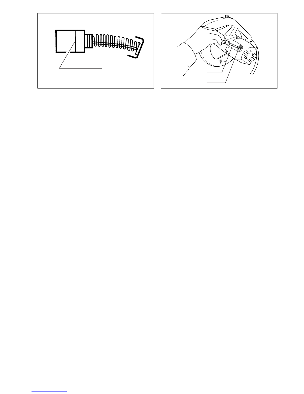
❏Do not place hand or fingers close to the blade.
❏Ne pas placer les mains ou les doigts près de la lame.
❏Halten Sie Hände oder Finger vom Sägeblatt fern.
❏Non avvicinare le mani o le dita alla lama.
❏Kom met uw handen of vingers niet te dicht bij het zaagblad.
❏No ponga la mano ni los dedos cerca del disco.
❏Não coloque a sua mão ou dedos perto da lâmina.
❏Hold hænder og fingre på god afstand af klingen.
❏Håll inte händer eller fingrar i närheten av klingan.
❏Ikke plasser hånd eller fingre i nærheten av bladet.
❏Älä sijoita käsiä äläkä sormia terän lähelle.
❏Μη βάζετε το χέρι ή τα δάκτυλα κοντά στην λάµα.
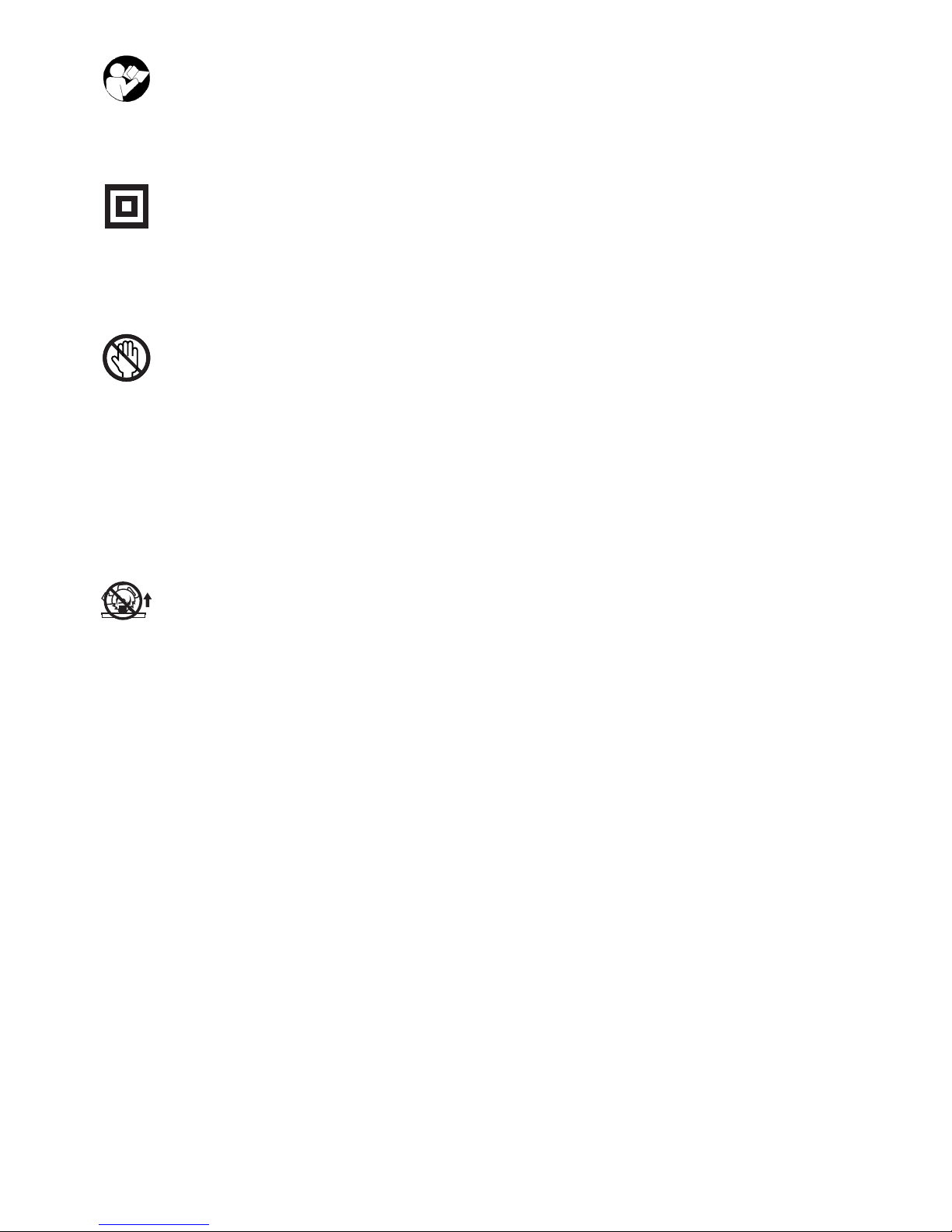
❏To avoid injury from flying debris, keep holding the saw head down, after making cuts, until the
blade has come to a complete stop.
❏Pour éviter les blessures causées par les objets projetés, maintenez la tête de la scie en position
basse une fois la coupe terminée, jusqu’à ce que la lame soit complètement arrêtée.
❏Um Verletzungen durch herausgeschleuderte Teile zu vermeiden, halten Sie den Sägekopf nach
Ausführung von Schnitten abgesenkt, bis das Sägeblatt völlig zum Stillstand gekommen ist.
❏Per evitare lesioni dalle schegge volanti, dopo aver eseguito il taglio tenere abbassata la testa
sega finché la lama non si è arrestata completamente.
❏Om verwonding door weggeslingerd zaagafval te voorkomen, dient u na het voltooien van een
snede de zaagkop omlaag te houden totdat het zaagblad volledig tot stilstand is gekomen.
❏Para evitar sufrir heridas a causa de restos que salen despedidos, siga sujetando la cabeza de la
sierra hacia abajo, al terminar los cortes, hasta que el disco se haya parado completamente.
❏Para evitar danos causados por aparas que saltem, mantenha a cabeça da serra para baixo,
depois de terminar os cortes, até que a lâmina esteja completamente parada.
❏For at undgå at komme til skade på grund af flyvende affald, skal man holde savhovedet nede efter
skæring, indtil savklingen står helt stille.
❏För att inte skadas av kringflygande flis efter genomförd sågning ska såghuvudet hållas nere tills
klingan har stannat helt.
❏For å unngå skader som følge av flygende flis, må du holde saghodet nede etter at sagingen er
avsluttet, helt til bladet har stoppet helt.
❏Pidä sahan pää sahauksen jälkeen alhaalla, kunnes saha on kokonaan pysähtynyt välttääksesi
lentävien roskien aiheuttaman loukkaantumisen.
❏Για να αποφύγετε τραυµατισµ απ ιπτάµενα τεµαχίδια, κρατάτε το πρινι µε το κεφάλι
προς τα κάτω, αφού κάνετε κοπές, µέχρι η λάµα να σταµατήσει τελείως.

9
❏For your safety, remove chips, small pieces, etc. from the table top before operation.
❏Pour votre sécurité, retirez les copeaux et autres petites pièces présentes sur la table avant de
commencer le travail.
❏Zur Sicherheit sollte die Tischplatte vor dem Betrieb von Spänen, Kleinteilen usw. gesäubert wer-
den.
❏Per la propria sicurezza, togliere i trucioli, frammenti, ecc., dalla superficie superiore del piano di
taglio prima di procedere.
❏Verwijder voor uw eigen veiligheid zaagafval, stukjes hout e.d. van de werktafel alvorens te gaan
zagen.
❏Por su propia seguridad, retire las virutas, trozos pequeños, etc., de encima de la mesa de trabajo
antes de iniciar la tarea.
❏Para sua segurança, retire aparas, peças pequenas, etc., de cima da bancada antes da operação.
❏Af sikkerhedsårsager skal spåner, små stykker etc. fjernes fra bordtoppen inden anvendelsen.
❏Av säkerhetsskäl bör flisor och småbitar avlägsnas från bordet före användningen.
❏For din egen sikkerhets skyld må du fjerne trebiter, flis osv. fra sagbordet før du begynner å bruke
maskinen.
❏Poista turvallisuuden vuoksi lastut, pienet palaset yms. pöydältä ennen työskentelyä.
❏Για την ασφάλειά σας, αφαιρέστε τα αποκοπίδια, µικρά κοµµάτια, κλπ. απ το τραπέζι πριν
απ την λειτουργία.
❏Always set SUB-FENCE to left position when performing left bevel cuts. Failure to do so may
cause serious injury to operator.
❏Lorsque vous effectuez des coupes en biseau sur la gauche, placez toujours la BUTÉE PARE-
ÉCLATS ROTATIVE à gauche. Sinon, il y a risque de blessure grave.
❏Stellen Sie den ZUSATZANSCHLAG bei der Durchführung von Neigungsschnitten immer auf die
linke Position. Anderenfalls kann die Bedienungsperson ernsthaft verletzt werden.
❏Posizionare sempre la guida pezzo secondaria a sinistra prima di eseguire i tagli a unghia. In caso
contrario, c’è pericolo di lesioni serie all’operatore.
❏Zet de HULPGELEIDER altijd in de linkse positie wanneer u linkse schuine sneden wilt zagen. Als
u dit niet doet, kan de gebruiker ernstige verwonding oplopen.
❏Ponga siempre la GUÍA AUXILIAR en la posición izquierda cuando realice cortes en bisel
izquierdo. De lo contrario, podrá sufrir graves heridas.
❏Coloque sempre a GUIA AUXILIAR no lado esquerdo quando executa cortes de bisel à esquerda.
Se não o fizer pode ferir o operador.
❏Anbing altid hjælpeanslaget (SUB-FENCE) i venstre position, når der laves skråsnit. Forsømmelse
af dette kan bevirke, at operatøren kommer alvorligt til skade.
❏Sätt alltid stödanhållet i vänsterläge vid vinkelsågning åt vänster. I annat fall kan användaren ska-
das allvarligt.
❏Ved gjæringssaging i vertikalplanet må du alltid sette HJELPEVERNET i venstre posisjon. Hvis
dette ikke gjøres, kan operatøren få alvorlige skader.
❏Aseta ALIOHJAIN aina vasemmalle tehdessäsi vasemmanpuoleisia viistesahauksia. Jos tätä ei
tehdä, käyttäjä voi loukkaantua vakavasti.
❏Πάντοτε ρυθµίζετε το SUB-FENCE (ΥΠΟ-ΦΡΑΚΤΗ) στην αριστερή θέση ταν εκτελείτε
αριστερές λοξές κοπές. Αµέλεια να το κάνετε µπορεί να προκαλέσει σοβαρ τραυµατισµ
στον χρήστη.

10
ENGLISH
Explanation of general view
1 Base
2Hexbolt
3 Auxiliary plate
4Nut
5Bolt
6 Center cover
7 Socket wrench
8 Shaft lock
9 Loosen
10 Arrow
11 Blade case
12 Arrow
13 Saw blade
14 Spindle
15 Flange
16 Ring
17 Flange
18 Hex bolt
19 Tighten
20 Safety cover
21 Dust spout
22 Dust bag
23 Fastener
24 Lock-off button
25 Switch trigger
26 Lever
27 Turn base
28 Kerf board
29 Sub-fence
30 Adjusting bolt
31 Pointer
32 Miter scale
33 Latch spring
34 Grip
35 Lever
36 Bevel scale
37 Pointer
38 Vise rod
39 Screws
40 Guide fence
41 Vise arm
42 Clamp screw
43 Support
44 Knob
45 Projection
46 Holder
47 Screw
48 Holder assembly
49 Screw
50 Rod 12
51 Cutting line
52 Groove
53 Vise
54 Spacer block
55 Aluminum extrusion
56 Spacer block
57 Over 10 mm
58 Over 460 mm
59 Hole
60 Set plate
61 Screw
62 Triangular rule
63 Hex bolts
64 Arm
65 Hex bolt (A)
66 Top surface of turn base
67 Arm holder
68 Hex bolt (B)
69 Limit mark
70 Screwdriver
71 Brush holder cap
SPECIFICATIONS
Model LS1040
Blade diameter .................................................................................................................................. 255 mm — 260 mm
Hole (arbor) diameter
For all countries other than European countries .......................................................................... 25.4 mm and 25 mm
For European countries ......................................................................................................................................30 mm
Max. cutting capacities (H x W) with blade 260 mm in diameter
No load speed (min–1) ............................................................................................................................................ 4,600
Dimensions (L x W x H) .....................................................................................................530 mm x 476 mm x 532 mm
Net weight ...............................................................................................................................................................11 kg
• Due to our continuing program of research and devel-
opment, the specifications herein are subject to change
without notice.
• Note: Specifications may differ from country to country.
Intended use
The tool is intended for accurate straight and miter cut-
ting in wood. With appropriate saw blades, aluminum can
also be sawed.
Power supply
The tool should be connected only to a power supply of
the same voltage as indicated on the nameplate, and can
only be operated on single-phase AC supply. They are
double-insulated in accordance with European Standard
and can, therefore, also be used from sockets without
earth wire.
For public low-voltage distribution systems of
between 220 V and 250 V
Switching operations of electric apparatus cause voltage
fluctuations. The operation of this device under unfavor-
able mains conditions can have adverse effects to the
operation of other equipment. With a mains impedance
equal or less than 0.30 Ohms it can be presumed that
there will be no negative effects. The mains socket used
for this device must be protected with a fuse or protective
circuit breaker having slow tripping characteristics.
Safety hints
For your own safety, please refer to enclosed safety
instructions.
Miter angle
Bevel angle 0° 45° (left and right)
0° 93 mm x 95 mm
69 mm x 135 mm 93 mm x 67 mm
69 mm x 95 mm
45° (left) 53 mm x 95 mm
35 mm x 135 mm 49 mm x 67 mm
35 mm x 94 mm

11
ADDITIONAL SAFETY RULES
1. Wear eye protection.
2. Do not operate saw without guards in place.
3. Don’t use the tool in the presence of flammable
liquids or gases.
4. Check the blade carefully for cracks or damage
before operation. Replace cracked or damaged
blade immediately.
5. Use only flanges specified for this tool.
6. Be careful not to damage the arbor, flanges
(especially the installing surface) or bolt. Dam-
age to these parts could result in blade break-
age.
7. Make sure that the turn base is properly secured
so it will not move during operation.
8. For your safety, remove the chips, small pieces,
etc. from the table top before operation.
9. Avoid cutting nails. Inspect for and remove all
nails from the workpiece before operation.
10. Make sure the shaft lock is released before the
switch is turned on.
11. Be sure that the blade does not contact the turn
base in the lowest position.
12. Hold the handle firmly. Be aware that the saw
moves up or down slightly during start-up and
stopping.
13. Do not perform any operation freehand. The
workpiece must be secured firmly against the
turn base and guide fence with the vise during
all operations. Never use your hand to secure
the workpiece.
14. Keep hands out of path of saw blade. Avoid con-
tact with any coasting blade. It can still cause
severe injury.
15. Never reach around saw blade.
16. Make sure the blade is not contacting the work-
piece before the switch is turned on.
17. Before using the tool on an actual workpiece, let
it run for a while. Watch for vibration or wobbling
that could indicate poor installation or a poorly
balanced blade.
18. Wait until the blade attains full speed before cut-
ting.
19. Stop operation immediately if you notice any-
thing abnormal.
20. Do not attempt to lock the trigger in the ON posi-
tion.
21. Shut off power and wait for saw blade to stop
before servicing or adjusting tool.
22. Be alert at all times, especially during repetitive,
monotonous operations. Don’t be lulled into a
false sense of security. Blades are extremely
unforgiving.
23. Always use accessories recommended in this
manual. Use of improper accessories such as
abrasive wheels may cause an injury.
24. Don’t abuse cord. Never yank cord to disconnect
it from the receptacle. Keep cord away from heat,
oil, water and sharp edges.
25. Do not use the saw to cut other than aluminum,
wood or similar materials.
26. Connect compound miter saws to a dust collect-
ing device when sawing.
27. Select saw blades in relation to the material to
be cut.
28. Take care when slotting.
29. Replace the kerf board when worn.
SAVE THESE INSTRUCTIONS.
OPERATING INSTRUCTIONS
Carrying tool (Fig. 1)
When carrying the tool, lower the handle fully and press
the stopper pin to lock the handle in the lowered position.
Secure the turn base by means of the grip. The tool can
then be conveniently carried by the carrying grip.
WARNING:
• Be sure that the tool is unplugged first.
• Stopper pin is for carrying purposes only and not for
any cutting operations.
Installing auxiliary plate (Fig.2& 3)
Install the auxiliary plate using the notch in the tool’s
base and secure it by tightening the hex bolt.
Bench mounting saw (Fig. 4)
This tool should be bolted with two bolts to a level and
stable surface using the bolt holes provided in the tool’s
base. This will help prevent tipping and possible injury.
Installing or removing saw blade
Important:
Always be sure that the tool is switched off and
unplugged before installing or removing the blade.
To remove the blade, use the socket wrench to loosen
the hex bolt holding the center cover by turning it more
than three turns counterclockwise. Raise the safety cover
and center cover. (Fig. 5)
Press the shaft lock so that the blade cannot revolve and
use the socket wrench to loosen the hex bolt clockwise.
Then remove the hex bolt, outer flange and blade.
(Fig. 6)
To install the blade, mount it onto the spindle, making
sure that the direction of the arrow on the surface of the
blade matches the direction of the arrow on the blade
case. (Fig. 7)
CAUTION:
• For all countries other than European countries
(Fig. 8)
The silver ring 25.4mm in outer diameter is factory-
installed onto the spindle. The black ring 25 mm in
outer diameter is included as standard equipment.
Before mounting the blade onto the spindle, always be
sure that the correct ring for the arbor hole of the blade
you intend to use is installed onto the spindle.
• For European countries (Fig. 8)
The ring 30 mm in outer diameter is factory-installed
onto the spindle.
Install the flange and hex bolt, and then use the socket
wrench to tighten the hex bolt securely counterclockwise
while pressing the shaft lock. Then tighten the hex bolt
clockwise to secure the center cover. (Fig. 9)
CAUTION:
Use only the Makita socket wrench provided to install or
remove the blade. Failure to do so may result in overtight-
ening or insufficient tightening of the hex bolt. This could
cause an injury.

12
Safety cover (Fig. 10)
When lowering the handle, the safety cover rises auto-
matically. The cover returns to its original position when
the cut is completed and the handle is raised. NEVER
DEFEAT OR REMOVE THE SAFETY COVER. In the
interest of your personal safety, always maintain the
safety cover in good condition. Any irregular operation of
the safety cover should be corrected immediately.
NEVER USE THE TOOL WITH A FAULTY SAFETY
COVER. If the see-through safety cover becomes dirty,
or sawdust adheres to it in such a way that the blade and/
or workpiece is no longer easily visible, unplug the saw
and clean the cover carefully with a damp cloth. Do not
use solvents or any petroleum-based cleaners on the
plastic cover.
Dust bag (Fig. 11 & 12)
The use of the dust bag makes cutting operations clean
and dust collection easy. To attach the dust bag, fit the
bag’s entry port over the dust spout. When the dust bag
is about half full, remove the dust bag from the tool and
pull the fastener out. Empty the dust bag of its contents,
tapping it lightly so as to remove particles adhering to the
insides which might hamper further collection.
Switch action
CAUTION:
• Before plugging in the tool, always check to see that
the switch trigger actuates properly and returns to the
“OFF” position when released.
• When not using the tool, remove the lock-off button and
store it in a secure place. This prevents unauthorized
operation.
• Do not pull the trigger hard without pressing in the lock-
off button. This can cause breakage of the switch.
For all countries other than European countries
(Fig. 13)
To prevent the trigger from being accidentally pulled, a
lock-off button is provided. To start the tool, press in the
lock-off button and pull the trigger. Release the trigger to
stop.
For European countries (Fig. 14)
To prevent the trigger from being accidentally pulled, a
lock-off button is provided. To start the tool, push the
lever to the left, press in the lock-off button and then pull
the trigger. Release the trigger to stop.
Kerf board (Fig. 15)
This tool is provided with the kerf board in the turn base.
If the kerf groove has not yet been cut in the kerf board by
the factory, you should cut the groove before actually
using the tool to cut a workpiece. Switch on the tool and
lower the blade gently to cut a groove in the kerf board.
Sub-fence (Fig. 16 & 17)
This tool is equipped with the sub-fence which should
ordinarily be positioned as shown in Fig. 16. However,
when performing left bevel cuts, set it to the left position
as shown in Fig. 17.
Maintaining maximum cutting capacity
(Fig. 18 & 19)
Unplug the tool before any adjustment is attempted. This
tool is factory adjusted to provide the max. cutting capac-
ity for a 260 mm saw blade. When the diameter of the
blade has been reduced due to sharpening, adjust the
depth adjusting bolt by turning it with the socket wrench.
The saw blade is lowered by turning the depth adjusting
bolt counterclockwise and raised by turning it clockwise.
Adjust so that when the handle is in the fully lowered
position, there will be a distance of about 135 mm from
the front face of the guide fence to the point where the
front edge of the blade enters the kerf. With the tool
unplugged, rotate the blade by hand while holding the
handle all the way down. Be sure that the blade does not
contact any part of the lower base when the handle is
lowered completely.
Positioning for adjusting the miter angle (Fig. 20)
Loosen the grip by turning counterclockwise. Turn the
turn base while pressing down the latch spring. When
you have moved the grip to the position where the pointer
indicates the desired angle on the miter scale, securely
tighten the grip clockwise.
CAUTION:
When turning the turn base, be sure to raise the handle
fully.
Positioning for adjusting the bevel angle
(Fig. 21 & 22)
The saw blade tilts up to 45° to the left only when the
sub-fence is set to the left position as shown in Fig. 17.
To adjust the bevel angle, loosen the lever at the rear of
the tool. Tilt the blade to the left so that the pointer indi-
cates the desired angle on the bevel scale. Then tighten
the lever firmly to secure the arm.
CAUTION:
When tilting the saw blade, be sure to raise the handle
fully.
Securing workpiece
WARNING:
It is extremely important to always secure the workpiece
properly and tightly with the vise. Failure to do so can
cause the tool to be damaged and/or the workpiece to be
destroyed. PERSONAL INJURY MAY ALSO RESULT.
Also, after a cutting operation, DO NOT raise the blade
until the blade has come to a complete stop.
1. Vertical vise (Fig. 23 &27)
The vertical vise can be installed on the guide fence
or the holder assembly (optional accessory). Insert
the vise rod into the hole in the guide fence or the
holder assembly and tighten the screw to secure the
vise rod. Position the vise arm according to the thick-
ness and shape of the workpiece and secure the
vise arm by tightening the screw. Press the work-
piece flat against the guide fence and the turn base.
Position the workpiece at the desired cutting position
and secure it firmly by tightening the clamp screw.
CAUTION:
The workpiece must be secured firmly against the
turn base and guide fence with the vise during all
operations.

13
If some part contacts the vise, re-position the vise
arm. Press the workpiece flat against the guide
fence and the turn base. Position the workpiece at
the desired cutting position and secure it firmly by
tightening the clamp screw of the vise.
CAUTION:
When cutting long workpieces, use supports that are
as high as the top surface level of the turn base.
(Fig. 24)
2. Horizontal vise (optional accessory)
(Fig. 25 & 26)
The horizontal vise can be installed on either the left
or right side of the base. When performing 15° or
greater miter cuts, install the horizontal vise on the
side opposite the direction in which the turn table is
to be turned. By turning the knob on the vise coun-
terclockwise, the screw is released and the vise
shaft can be moved rapidly in and out. By turning the
knob clockwise, the screw remains secured. To grip
workpieces, turn the knob gently clockwise until the
projection reaches its topmost position, then fasten
securely. If the knob is forced in or pulled out while
being turned clockwise, the projection may stop at
an angle. In this case, turn the knob back counter-
clockwise until the screw is released, before turning
again gently clockwise.
3. Holders and holder assembly (optional accesso-
ries)
The holders and the holder assembly can be
installed on either side as a convenient means of
supporting workpieces horizontally. Install them as
shown in Fig.27. Then tighten the screws firmly to
secure the holders and the holder assembly.
(Fig. 27)
When cutting long workpieces, use the holder-rod
assembly (optional accessory). It consists of two
holder assemblies and two rods 12. (Fig. 28)
CAUTION:
Always support long workpieces level with the top
surface of the turn base for accurate cuts and to pre-
vent dangerous loss of control of the tool.
Operation
CAUTION:
• Before use, be sure to release the handle from the low-
ered position by pulling the stopper pin.
• Make sure the blade is not contacting the workpiece,
etc. before the switch is turned on.
• Do not apply excessive pressure on the handle when
cutting. Too much force may result in overload of the
motor and/or decreased cutting efficiency.
• Gently press down the handle to perform the cut. If the
handle is pressed down with force or if lateral force is
applied, the blade will vibrate and leave a mark (saw
mark) in the workpiece and the precision of the cut will
be impaired.
When cutting with this tool, the thickness of the blade is
cut out of the workpiece as well. Therefore, your cutting
line should be on either the left or right side of the groove
in the kerf board. Switch on the tool and wait until the
blade attains full speed before lowering gently into the
cut. When the blade contacts the workpiece, gradually
bear down on the handle to perform the cut. When the
cut is completed, switch off the tool and WAIT UNTIL
THE BLADE HAS COME TO A COMPLETE STOP
before returning the blade to its fully elevated position. A
thin piece of cut off material could otherwise contact the
coasting blade and be thrown around dangerously.
(Fig. 29)
1. Miter cutting
Refer to the previously covered “Positioning for
adjusting the miter angle”.
2. Bevel cut (Fig. 30)
• Left 0° – 45° bevel cuts can be performed.
• Set the sub-fence to the left position as shown in
Fig. 17. Loosen the lever and tilt the saw blade to
set the bevel angle. Be sure to retighten the lever
firmly to secure the selected bevel angle safely.
Secure the workpiece with the vise. Switch on the
tool and wait until the blade attains full speed.
Then gently lower the handle to the fully lowered
position while applying pressure in parallel with the
blade. When the cut is completed, switch off the
tool and WAIT UNTIL THE BLADE HAS COME TO
A COMPLETE STOP before returning the blade to
its fully elevated position.
CAUTION:
• When performing the bevel cut with the workpiece
secured on the left side of the turn base, it will cre-
ate a condition where the piece cut off will come to
rest on the blade. If the blade is raised while the
blade is still rotating, this piece may be caught in
the blade, causing fragments to be scattered
around which is dangerous. The blade should be
gently raised only after the blade has come to a
complete stop.
• When pressing down the handle, apply pressure in
parallel with the blade. If a force is applied perpen-
dicularly to the turn base or if the pressure direc-
tion is changed during a cut, the precision of the
cut will be impaired.
• Always set the sub-fence to the left position as
shown in Fig. 17 when performing bevel cuts.
3. Compound cutting
Compound cutting can be performed at angle shown
in the table below.
When performing the compound cutting, refer to
“Miter cutting” and “Bevel cut” explanations.
Bevel angle Miter angle
45° Left and right
0° – 45°

14
4. Cutting aluminum extrusion (Fig. 31)
When securing aluminum extrusions, use spacer
blocks or pieces of scrap as shown in Fig. 31 to pre-
vent deformation of the aluminum. Use a cutting
lubricant when cutting the aluminum extrusion to
prevent build-up of the aluminum material on the
blade.
CAUTION:
Never attempt to cut thick or round aluminum extru-
sions. Thick aluminum extrusions may come loose
during operation and round aluminum extrusions
cannot be secured firmly with this tool.
5. Wood facing (Fig. 32)
Use of wood facing helps to assure splinter-free cuts
in workpieces. Attach a wood facing to the guide
fence using the holes in the guide fence.
CAUTION:
• Use straight wood of even thickness as the wood
facing.
•SeeFig. 32 concerning the dimensions for a sug-
gested wood facing.
6. Cutting repetitive lengths (Fig. 33)
When cutting several pieces of stock to the same
length, ranging from 240 mm to 400 mm, use of the
set plate (optional accessory) will facilitate more effi-
cient operation. Install the set plate on the holder as
shown in Fig. 33. Align the cutting line on your work-
piece with either the left or right side of the groove in
the kerf board, and while holding the workpiece from
moving, move the set plate flush against the end of
the workpiece. Then secure the set plate with the
screw. When the set plate is not used, loosen the
screw and turn the set plate out of the way.
MAINTENANCE
CAUTION:
Always be sure that the tool is switched off and
unplugged before carrying out any work on the tool.
Adjusting the cutting angle
This tool is carefully adjusted and aligned at the factory,
but rough handling may have affected the alignment. If
your tool is not aligned properly, perform the following:
1) Miter angle (Fig. 34 & 35)
Loosen the grip and set the turn base at zero
degrees by turning the turn base. Tighten the grip
securely and loosen the hex bolts on the guide
fence. Square the side of the blade with the face of
the guide fence using a triangular rule, try-square,
etc. by moving the right side of the guide fence.
Then securely tighten the hex bolts on the guide
fence in the order indicated in Fig. 35.
2) Bevel angle
i) 0° bevel angle
Loosen the lever at the rear of the tool. Loosen
the hex nut and turn the hex bolt (A) two or three
revolutions clockwise so that the blade tilts to the
right. (Fig. 36)
Lower the handle fully and square the side of the
blade with the top surface of the turn base using
the triangular rule, try-square, etc. by turning the
hex bolt (A) counterclockwise. Then tighten the
hex nut to secure the hex bolt (A). (Fig. 37)
Make sure that the pointer on the arm indicates
0° on the bevel scale on the arm holder. If the
pointer does not indicate 0°, loosen the screw
securing the pointer and adjust the pointer.
(Fig. 38)
ii) 45° bevel angle
Adjust 45° bevel angle only after performing 0°
bevel angle adjustment. To adjust 45° bevel
angle, loosen the lever and tilt the saw blade to
the left fully. Make sure that the pointer on the
arm indicates 45° on the bevel scale on the arm
holder. If the pointer does not indicate 45°, turn
the hex bolt (B) on the side of the arm until the
pointer indicates 45°. (Fig. 38)
Replacement of carbon brushes
(Fig. 39 & 40)
Replace carbon brushes when they are worn down to the
limit mark. Both identical carbon brushes should be
replaced at the same time.
To maintain product safety and reliability, repairs, mainte-
nance or adjustment should be carried out by a Makita
Authorized Service Center.

33
NEDERLANDS
Verklaring van algemene gegevens
1 Voetstuk
2 Zeskante bout
3 Hulpplaat
4Moer
5Bout
6 Middenkap
7 Dopsleutel
8 Asvergrendeling
9 Losmaken
10 Pijl
11 Zaagbladkast
12 Pijl
13 Zaagblad
14 As
15 Flens
16 Ring
17 Flens
18 Zeskante bout
19 Vastmaken
20 Veiligheidskap
21 Stofuitlaat
22 Stofzak
23 Sluiting
24 Ontgrendelknop
25 Trekkerschakelaar
26 Hendel
27 Draaibaar voetstuk
28 Zaagsnede-plaat
29 Hulpgeleider
30 Stelbout
31 Wijzer
32 Verstekschaal
33 Slotveer
34 Handgreep
35 Hendel
36 Schuine-hoek schaal
37 Wijzer
38 Spanschroefstang
39 Schroeven
40 Geleider
41 Spanschroefarm
42 Klembout
43 Steun
44 Knop
45 Uitsteeksel
46 Houder
47 Schroef
48 Houdermontage
49 Schroef
50 Stang 12
51 Zaaglijn
52 Groef
53 Spanschroef
54 Vulblok
55 Aluminium werkstuk
56 Vulblok
57 Meer dan 10 mm
58 Meer dan 460 mm
59 Gat
60 Stelplaat
61 Schroef
62 Driehoeksliniaal
63 Zeskante bouten
64 Arm
65 Zeskante bout (A)
66 Bovenvlak van draaibaar
voetstuk
67 Armhouder
68 Zeskante bout (B)
69 Limietmerkstreep
70 Schroevedraaier
71 Borstelhouderdop
TECHNISCHE GEGEVENS
Model LS1040
Diameter van zaagblad .....................................................................................................................255 mm — 260 mm
Diameter van gat (asgat)
Voor alle niet-Europese landen ...................................................................................................... 25,4 mm en 25 mm
Voor alle Europese landen ................................................................................................................................. 30 mm
Max. zaagkapaciteiten (H x B) met een zaagblad van 260 mm in diameter
Toerental onbelast (min–1) ...................................................................................................................................... 4 600
Afmetingen (L x B x H) ......................................................................................................530mmx476mmx532mm
Netto gewicht .......................................................................................................................................................... 11 kg
• In verband met ononderbroken research en ontwikke-
ling behouden wij ons het recht voor bovenstaande
technische gegevens te wijzigen zonder voorafgaande
kennisgeving.
• Opmerking: De technische gegevens kunnen van land
tot land verschillen.
Doeleinden van gebruik
Dit gereedschap is bedoeld voor nauwkeurig recht zagen
en verstekzagen in hout. Bij gebruik van de geschikte
zaagbladen kan ook aluminium worden gezaagd.
Stroomvoorziening
Het gereedschap mag alleen worden aangesloten op
een stroombron van hetzelfde voltage als aangegeven op
de naamplaat, en kan alleen op enkel-fase wisselstroom
worden gebruikt. Het gereedschap is dubbel-geïsoleerd
volgens de Europese standaard en kan derhalve ook op
een niet-geaard stopcontact worden aangesloten.
Verstekhoek
Schuine hoek 0° 45° (links en rechts)
0° 93 mm x 95 mm
69 mm x 135 mm 93 mm x 67 mm
69 mm x 95 mm
45° (links) 53 mm x 95 mm
35 mm x 135 mm 49 mm x 67 mm
35 mm x 94 mm

34
Voor openbare laagspanningsverdeelsystemen van
tussen 220 V en 250 V
Schakelbedieningen van elektrische toestellen veroorza-
ken spanningsschommelingen. De bediening van dit
gereedschap onder ongunstige lichtnetomstandigheden
kan een nadelige invloed hebben op de bediening van
andere apparatuur. Het kan worden aangenomen dat er
geen negatieve effecten zullen zijn wanneer de netimpe-
dantie gelijk is aan of minder is dan 0,30 Ohm.
Het stopcontact dat voor dit gereedschap wordt gebruikt,
moet beveiligd zijn door een zekering of een stroomon-
derbreker met trage afschakelkarakteristieken.
Veiligheidswenken
Voor uw veiligheid dient u de bijgevoegde Veiligheids-
voorschriften nauwkeurig op te volgen.
AANVULLENDE
VEILIGHEIDSVOORSCHRIFTEN
1. Draag oogbescherming.
2. Gebruik de zaag niet zonder dat de bescherm-
kappen zijn aangebracht.
3. Gebruik de machine niet in de nabijheid van ont-
vlambare vloeistoffen of gassen.
4. Controleer het zaagblad zorgvuldig op barsten of
beschadiging, alvorens de machine te gaan
gebruiken. Een gebarsten of beschadigd zaag-
blad dient onmiddellijk te worden vervangen.
5. Gebruik alleen flenzen die voor deze machine
gemaakt zijn.
6. Zorg ervoor dat de as, de flenzen (vooral het
montagevlak) of de bout niet worden bescha-
digd. Beschadiging van deze onderdelen kan
zaagbladbreuk veroorzaken.
7. Controleer of het draaibaar voetstuk goed vast-
zit, zodat het tijdens het zagen niet kan bewegen.
8. Verwijder voor uw eigen veiligheid zaagafval,
kleine stukjes hout e.d. van de werktafel alvo-
rens te gaan zagen.
9. Zaag niet op spijkers. Inspecteer het werkstuk en
verwijder alle eventuele spijkers alvorens met
het zagen te beginnen.
10. Zet de asvergrendeling in de vrije stand alvorens
de trekkerschakelaar in te drukken.
11. Zorg ervoor dat het zaagblad in zijn laagste posi-
tie niet in aanraking komt met het draaibaar voet-
stuk.
12. Houd het handvat stevig vast. Denk eraan dat de
zaag bij het starten en stoppen een beetje op- en
neergaat.
13. Zaag nooit met het werkstuk in uw hand. Zet het
werkstuk altijd stevig vast op het draaibaar voet-
stuk en tegen de geleider met behulp van de
spanschroef. Gebruik nooit uw hand om het
werkstuk vast te houden.
14. Houd altijd uw handen uit de buurt van het zaag-
blad. Raak het freewheelende zaagblad niet aan,
aangezien dit nog ernstige verwondingen kan
veroorzaken.
15. Probeer tijdens het zagen nooit iets vast te pak-
ken in de omgeving van het zaagblad.
16. Controleer vóór het inschakelen of het zaagblad
niet in contact is met het werkstuk.
17. Laat de machine een tijdje draaien alvorens deze
op het werkstuk te gebruiken. Controleer op tril-
lingen of schommelingen die op onjuiste instal-
latie of op een slecht gebalanceerd zaagblad
kunnen wijzen.
18. Wacht totdat het zaagblad op volle toeren draait,
alvorens het werkstuk te zagen.
19. Stop onmiddellijk met zagen indien u iets abnor-
maals opmerkt.
20. Probeer niet de trekkerschakelaar in de AAN
positie te vergrendelen.
21. Schakel de spanning uit en wacht totdat het
zaagblad volledig tot stilstand is gekomen, alvo-
rens de machine een onderhoudsbeurt te geven
of af te stellen.
22. Laat uw aandacht nooit verslappen, vooral niet
wanneer het werk saai is en uit herhalingen
bestaat. Laat u niet door een vals gevoel van vei-
ligheid misleiden, aangezien zaagbladen altijd
gevaar kunnen opleveren.
23. Gebruik uitsluitend de accessoires die in deze
gebruiksaanwijzing worden aanbevolen. Het
gebruik van ongeschikte accessoires, zoals
slijpschijven, kan verwonding veroorzaken.
24. Houd het snoer in goede conditie. Trek aan de
stekker en niet aan het snoer zelf om dit uit het
stopcontact te verwijderen. Houd het snoer uit
de buurt van hitte, olie, water en scherpe randen.
25. Gebruik de zaag niet voor het zagen van andere
materialen dan aluminium, hout of gelijksoortige
materialen.
26. Sluit gecombineerde verstekzagen tijdens het
zagen aan op een stofvanginrichting.
27. Kies de zaagbladen in overeenstemming met het
te zagen materiaal.
28. Wees voorzichtig wanneer u gleuven zaagt.
29. Vervang de zaagsnede-plaat wanneer deze ver-
sleten is.
BEWAAR DEZE VOORSCHRIFTEN.
BEDIENINGSVOORSCHRIFTEN
Dragen van de machine (Fig. 1)
Om de machine te dragen, brengt u het handvat hele-
maal omlaag en drukt u de aanslagpen naar binnen om
het handvat in de omlaagpositie vast te zetten. Zet het
draaibaar voetstuk vast door middel van de handgreep.
De machine kan dan gemakkelijk bij de handgreep wor-
den gedragen.
WAARSCHUWING:
• Trek eerst de stekker van de machine uit het stopcon-
tact.
• De aanslagpen is uitsluitend bedoeld voor het dragen
van de machine en niet voor zaagbedieningen.
Installeren van de hulpplaat (Fig. 2 en 3)
Installeer de hulpplaat door gebruik te maken van de
inkeping in het machinevoetstuk en zet deze vast door de
zeskante bout aan te trekken.
De zaag op een werktafel monteren (Fig. 4)
Deze machine moet op een horizontaal en stabiel opper-
vlak worden gemonteerd door middel van twee bouten
die u door de boutgaten in het machinevoetstuk steekt.
Hierdoor wordt voorkomen dat de machine omkantelt en
mogelijk verwondingen veroorzaakt.

35
Installeren of verwijderen van het zaagblad
Belangrijk:
Controleer altijd of de machine is uitgeschakeld en de
stekker van het netsnoer uit het stopcontact is getrokken
alvorens het zaagblad te installeren of te verwijderen.
Om het zaagblad te verwijderen, gebruik de dopsleutel
en draai de zeskante bout, waarmee de middenkap is
vastgezet, meer dan drie slagen naar links om deze los
te maken. Breng de veiligheidskap en de middenkap
omhoog. (Fig. 5)
Druk op de asvergrendeling zodat het blad niet kan rond-
draaien en draai met de dopsleutel de zeskante bout
naar rechts los. Verwijder vervolgens de zeskante bout,
de buitenflens en het zaagblad. (Fig. 6)
Om het zaagblad te installeren, monteert u het zaagblad
op de as, ervoor zorgend dat de pijlen op het zaagblad
en op de zaagbladkast in dezelfde richting wijzen.
(Fig. 7)
LET OP:
•Voor alle niet-Europese landen (Fig. 8)
De zilverring met een buitendiameter van 25,4 mm is in
de fabriek op de as gemonteerd. De zwarte ring met
een buitendiameter van 25 mm is als standaard uitrus-
ting meegeleverd. Alvorens het blad op de as te monte-
ren, moet u altijd ervoor zorgen dat de ring die geschikt
is voor het asgat van het blad dat u gaat gebruiken, op
de as is gemonteerd.
•Voor Europese landen (Fig. 8)
De ring met een buitendiameter van 30 mm is in de
fabriek op de as gemonteerd.
Monteer de flens en de zeskante bout, en draai dan met
de dopsleutel de zeskante bout stevig naar links vast ter-
wijl u de asvergrendeling ingedrukt houdt. Zet daarna de
middenkap vast door de zeskante bout naar rechts vast
te draaien. (Fig. 9)
LET OP:
Gebruik voor het installeren of verwijderen van het zaag-
blad uitsluitend de bijgeleverde Makita dopsleutel. Doet u
dit niet, dan kan de zeskante bout te vast of te los worden
aangedraaid, hetgeen verwondingen tot gevolg kan heb-
ben.
Veiligheidskap (Fig. 10)
Wanneer het handvat omlaag wordt gebracht, gaat de
veiligheidskap automatisch omhoog. De veiligheidskap
keert naar haar oorspronkelijke positie terug wanneer het
zagen beëindigd is en het handvat omhoog wordt
gebracht. ZET DE VEILIGHEIDSKAP NOOIT VAST EN
VERWIJDER DEZE NOOIT. Voor uw persoonlijke veilig-
heid dient de veiligheidskap altijd in goede staat te wor-
den gehouden. Elke onregelmatigheid in de werking van
de veiligheidskap dient onmiddellijk te worden hersteld.
GEBRUIK DE MACHINE NOOIT MET EEN DEFECTE
VEILIGHEIDSKAP. Wanneer de doorzichtige veiligheids-
kap vuil is of met zaagsel is bedekt zodat u het zaagblad
en/of het werkstuk niet meer behoorlijk kunt zien, verwij-
der dan de stekker uit het stopcontact en reinig de veilig-
heidskap zorgvuldig met een bevochtigde doek. Gebruik
geen oplosmiddelen of benzinehoudende schoonmaak-
middelen op de plastic kap.
Stofzak (Fig. 11 en 12)
Door de stofzak te gebruiken wordt het zaagsel opgevan-
gen en kunt u schoon werken. Voor het bevestigen van
de stofzak monteert u de inlaat van de stofzak over de
stofuitlaat op de machine. Wanneer de stofzak ongeveer
halfvol is, verwijdert u deze van de machine en trekt u de
sluiting eruit. Maak de stofzak leeg en tik er lichtjes op
voor het verwijderen van achtergebleven stofdeeltjes
waardoor de stofopvanging zou kunnen worden belem-
merd.
Werking van de schakelaar
LET OP:
• Alvorens de stekker in het stopcontact te steken, dient
u altijd te controleren of de trekkerschakelaar goed
werkt en bij loslaten naar de “OFF” stand terugkeert.
• Verwijder de ontgrendelknop en bewaar deze op een
veilige plaats wanneer u de machine niet gebruikt.
Hierdoor voorkomt u ongeoorloofd gebruik van de
machine.
• Druk de trekkerschakelaar niet hard in zonder de ont-
grendelknop in te drukken. Hierdoor kan de schakelaar
namelijk breken.
Voor alle niet-Europese landen (Fig. 13)
Een ontgrendelknop is voorzien om te voorkomen dat de
trekkerschakelaar per ongeluk wordt ingedrukt. Om de
machine te starten, drukt u de ontgrendelknop in en
daarna drukt u de trekkerschakelaar in. Om de machine
te stoppen, laat u de trekkerschakelaar los.
Voor Europese landen (Fig. 14)
Een ontgrendelknop is voorzien om te voorkomen dat de
trekkerschakelaar per ongeluk wordt ingedrukt. Om de
machine te starten, duw de hendel naar links, druk de
ontgrendelknop in en druk daarna de trekkerschakelaar
in. Om de machine te stoppen, laat u de trekkerschake-
laar los.
Zaagsnede-plaat (Fig. 15)
Deze machine is voorzien van een zaagsnede-plaat in
het draaibaar voetstuk. Indien de zaagsnede-groef in de
fabriek nog niet in de zaagsnede-plaat is gezaagd, dient
u de groef erin te zagen alvorens de machine te gebrui-
ken voor het zagen van een werkstuk. Schakel de
machine in en breng het zaagblad langzaam omlaag om
een groef in de zaagsnede-plaat te zagen.
Hulpgeleider (Fig. 16 en 17)
Deze machine is voorzien van een hulpgeleider die nor-
maal in de positie afgebeeld in Fig. 16 moet staan. Wan-
neer u echter linkse schuine sneden wilt maken, moet u
deze geleider in de linkerpositie afgebeeld in Fig. 17 zet-
ten.

36
Handhaven van de maximale zaagcapaciteit
(Fig. 18 en 19)
Trek de stekker van de machine uit het stopcontact alvo-
rens afstellingen te maken. Deze machine is in de fabriek
ingesteld voor het leveren van maximale zaagcapaciteit
met een 260 mm zaagblad. Wanneer de diameter van
het zaagblad vanwege herhaald aanscherpen is geslon-
ken, dient u de diepte-afstelbout af te stellen door deze
met de dopsleutel te draaien. Draai de diepte-afstelbout
naar links om het zaagblad in een lagere positie te zet-
ten, en naar rechts om het in een hogere positie te zet-
ten. Stel zodanig af dat de afstand tussen het voorvlak
van de geleider en het punt waar de voorrand van het
zaagblad in de zaagsnede komt ongeveer 135 mm
bedraagt wanneer het handvat zich in de laagste positie
bevindt. Draai met de hand het zaagblad rond (met de
stekker uit het stopcontact!) terwijl u het handvat volledig
omlaag gedrukt houdt, en controleer of het zaagblad met
geen enkel deel van het onderste voetstuk in aanraking
komt wanneer het handvat helemaal omlaag is gebracht.
Instellen van de verstekhoek (Fig. 20)
Draai de handgreep naar links los. Verdraai het draaibaar
voetstuk terwijl u de slotveer omlaag gedrukt houdt.
Beweeg de handgreep naar de positie waarbij de wijzer
de gewenste hoek op de verstekschaal aanwijst en draai
dan de handgreep weer stevig naar rechts vast.
LET OP:
Voor het verdraaien van het draaibaar voetstuk dient u
het handvat in de hoogste positie te plaatsen.
Instellen van de schuine hoek (Fig. 21 en 22)
Het zaagblad kan 45° schuin omhoog naar links worden
gezet alleen wanneer de hulpgeleider in de linker positie
is gezet, zoals afgebeeld in Fig. 17. Om de schuine hoek
in te stellen, maakt u de hendel aan de achterzijde van
de machine los. Kantel het zaagblad naar links zodat de
wijzer naar de gewenste hoek op de schuine-hoek schaal
wijst. Draai daarna de hendel weer vast om de arm te
vergrendelen.
LET OP:
Voor het schuin zetten van het zaagblad, dient u het
handvat in de hoogste positie te plaatsen.
Vastzetten van het werkstuk
WAARSCHUWING:
Het is uiterst belangrijk dat u het werkstuk altijd juist en
stevig vastzet met behulp van de spanschroef. Wanneer
u dit nalaat, kan de machine beschadiging oplopen en/of
het werkstuk worden vernield. OOK KAN PERSOON-
LIJK LETSEL HET GEVOLG ZIJN. Nadat het zagen is
beëindigd, dient u de zaag NIET op te tillen alvorens het
zaagblad volledig tot stilstand is gekomen.
1. Verticale spanschroef (Fig. 23 en 27)
De verticale spanschroef kan op de geleider of op
de houdermontage (los verkrijgbaar accessoire)
worden geïnstalleerd. Steek de stang van de span-
schroef in het gat in de geleider of in de houdermon-
tage en trek de schroef aan om de stang vast te
zetten. Zet de arm van de spanschroef in de positie
die geschikt is voor de dikte en vorm van het werk-
stuk en zet de arm vast door de schroef vast te
draaien. Druk het werkstuk vlak tegen de geleider
en het draaibare voetstuk. Plaats het werkstuk in de
gewenste zaagpositie en zet het stevig vast door de
klemschroef vast te draaien.
LET OP:
Tijdens alle bedieningen moet het werkstuk door de
spanschroef stevig tegen het draaibaar voetstuk en
de geleider worden gedrukt.
Indien sommige delen met de spanschroef in aanra-
king komen, moet u de positie van de spanschroe-
farm opnieuw afstellen. Druk het werkstuk vlak
tegen de geleider en het draaibaar voetstuk. Plaats
het werkstuk in de gewenste zaagpositie en zet het
stevig vast door de klembout van de spanschroef
vast te draaien.
LET OP:
Voor het zagen van lange werkstukken dient u
gebruik te maken van steunders die even hoog zijn
als het bovenvlak van het draaibaar voetstuk.
(Fig. 24)
2. Horizontale spanschroef
(los verkrijgbaar accessoire) (Fig. 25 en 26)
De horizontale spanschroef kan aan de linker- of
rechterzijde van het voetstuk worden geïnstalleerd.
Voor het maken van versteksneden van 15° of meer,
monteert u de horizontale spanschroef aan de
tegenovergestelde zijde van de richting waarin het
draaibare voetstuk zal worden gedraaid. Wanneer
de knop op de spanschroef naar links wordt
gedraaid, komt de schroef los en kunt u de as van
de spanschroef snel naar binnen en naar buiten
bewegen. Wanneer de knop naar rechts wordt
gedraaid, blijft de schroef vast. Om het werkstuk te
grijpen, draait u de knop langzaam naar rechts tot-
dat het uitsteeksel in zijn hoogste positie komt te
staan, en dan draait u de knop stevig vast. Indien de
knop naar binnen of naar buiten wordt getrokken ter-
wijl u deze naar rechts draait, kan het uitsteeksel in
een schuine positie stoppen. In dit geval draait u de
knop terug naar links totdat de schroef los komt, en
dan draait u deze weer langzaam naar rechts.

37
3. Houders en houdermontage
(los verkrijgbare accessoires)
De houders en de houdermontage kunnen aan
beide zijden van de machine worden aangebracht
als een handig middel voor het horizontaal onder-
steunen van de werkstukken. Monteer deze zoals
afgebeeld in Fig. 27. Trek de schroeven stevig aan
om de houders en de houdermontage vast te zetten.
(Fig. 27)
Gebruik de houder/stang montage (los verkrijgbaar
accessoire) voor het zagen van lange werkstukken.
Deze bestaat uit twee houdermontages en twee
stangen 12. (Fig. 28)
LET OP:
Om nauwkeurige zaagsneden te verkrijgen en
gevaarlijk controleverlies van de machine te voorko-
men, dient u lange werkstukken altijd zo te onder-
steunen dat deze op gelijke hoogte staan met het
bovenvlak van het draaibare voetstuk.
Bediening
LET OP:
• Alvorens de machine wordt ingeschakeld, dient het
handvat uit zijn laagste positie te worden gehaald door
de borgpen naar buiten te trekken.
• Zorg ervoor dat het zaagblad niet in aanraking is met
het werkstuk e.d. voordat de machine wordt ingescha-
keld.
• Oefen tijdens het zagen geen overmatige druk op het
handvat uit. Wanneer u te hard drukt, kan de motor
overbelast raken en/of de zaagcapaciteit verminderen.
• Druk het handvat zachtjes naar beneden om te zagen.
Indien het handvat met geweld naar beneden wordt
gedrukt of zijwaartse druk erop wordt uitgeoefend, zal
het zaagblad trillen en een merkteken (zaagteken) in
het werkstuk achterlaten, en zal ook de zaagsnede
minder nauwkeurig zijn.
Wanneer u met deze machine zaagt, wordt de dikte van
het zaagblad ook van het werkstuk afgezaagd. Zorg
daarom ervoor dat uw zaaglijn zich aan de linker- of
rechterzijde van de groef in de zaagsnede-plaat bevindt.
Schakel de machine in, wacht totdat het zaagblad op
volle snelheid draait, en laat dan de zaag voorzichtig op
het werkstuk neerzakken. Wanneer het zaagblad het
werkstuk raakt, drukt u het handvat geleidelijk neer.
Nadat het zagen is beëindigd, schakelt u de machine uit.
WACHT TOTDAT HET ZAAGBLAD VOLLEDIG TOT
STILSTAND IS GEKOMEN alvorens het zaagblad weer
naar zijn hoogste positie te brengen. Een afgezaagd
stukje zou anders met het nog draaiende zaagblad in
aanraking kunnen komen en als een gevaarlijk projectiel
in het rond worden geslingerd. (Fig. 29)
1. Verstekzagen
Zie de paragraaf “Instellen van de verstekhoek” hier-
boven.
2. Schuine sneden zagen (Fig. 30)
• Linkse sneden van 0° tot 45° kunnen worden
gezaagd.
• Zet de hulpgeleider in de linker positie zoals afge-
beeld in Fig. 17. Draai de hendel los en houd het
zaagblad schuin om de schuine hoek in te stellen.
Draai daarna de hendel weer stevig vast om de
ingestelde schuine hoek goed vast te houden. Zet
het werkstuk vast met de spanschroef. Schakel de
machine in en wacht totdat het zaagblad op volle
toeren draait. Breng dan het handvat langzaam tot
in de laagste positie terwijl u druk uitoefent even-
wijdig met het zaagblad. Nadat het zagen is beëin-
digd, schakelt u de machine uit. WACHT TOTDAT
HET ZAAGBLAD VOLLEDIG TOT STILSTAND IS
GEKOMEN alvorens het zaagblad weer naar zijn
hoogste positie te brengen.
LET OP:
• Wanneer u een schuine snede zaagt met het
werkstuk vastgezet aan de linkerzijde van het
draaibare voetstuk, zal het afgezaagde stuk op het
zaagblad komen te liggen. Als het zaagblad
omhoog wordt gebracht terwijl het nog draait, kan
dit stuk door het zaagblad worden gegrepen zodat
brokstukken in het rond worden geslingerd, het-
geen natuurlijk gevaarlijk is. Breng daarom het
zaagblad langzaam omhoog alleen nadat dit volle-
dig tot stilstand is gekomen.
• Wanneer u het handvat omlaag drukt, dient u druk
uit te oefenen evenwijdig met het zaagblad. Als u
verticale druk op het draaibare voetstuk uitoefent
of de drukrichting tijdens het zagen verandert, zal
de zaagsnede minder nauwkeurig zijn.
• Voor het zagen van schuine sneden, dient u de
hulpgeleider altijd in de linker positie te zetten,
zoals afgebeeld in Fig. 17.
3. Gecombineerd zagen
Gecombineerd zagen is mogelijk voor de hoeken
aangegeven in de onderstaande tabel.
Voor gecombineerd zagen, zie de uitleg onder “Ver-
stekzagen” en “Schuine sneden zagen.”
Schuine hoek Verstekhoek
45° Links en rechts
0° – 45°

38
4. Zagen van aluminium werkstukken (Fig. 31)
Gebruik voor het vastzetten van aluminium werk-
stukken, vulblokken of afgedankte blokstukken,
zoals afgebeeld in Fig. 31, om vervorming van de
aluminium te voorkomen. Gebruik voor het zagen
ook zaagolie, om te voorkomen dat aluminium zaag-
sel zich op het zaagblad ophoopt.
LET OP:
Probeer nooit dikke of ronde aluminium werkstukken
te zagen. Dikke aluminium werkstukken kunnen tij-
dens het zagen losraken, en ronde aluminium werk-
stukken kunnen op deze zaagmachine niet worden
vastgezet.
5. Houten spanplaat (Fig. 32)
Gebruik een houten spanplaat om zaagsneden zon-
der splinters te verkrijgen. Bevestig een houten
spanplaat aan de geleider door de gaten in de gelei-
der te gebruiken.
LET OP:
• Gebruik recht hout van gelijke dikte voor de houten
spanplaat.
•ZieFig. 32 voor de afmetingen van de aanbevolen
spanplaat.
6. Stukken van gelijke lengte zagen (Fig. 33)
Wanneer u verschillende stukken van dezelfde
lengte tussen 240 mm en 400 mm wilt zagen, kunt u
doeltreffender werken door de stelplaat (los verkrijg-
baar accessoire) te gebruiken. Monteer de stelplaat
op de houder zoals afgebeeld in Fig. 33. Breng de
zaaglijn op uw werkstuk op één lijn met de linker-
zijde of de rechterzijde van de groef in de
zaagsnede-plaat. Houd het werkstuk vast zodat het
niet kan bewegen, en plaats de stelplaat vlak tegen
het einde van het werkstuk. Zet daarna de stelplaat
vast met de schroef. Wanneer u de stelplaat niet
gebruikt, draait u de schroef los en draait u de stel-
plaat uit de weg.
ONDERHOUD
LET OP:
Zorg er altijd voor dat de machine is uitgeschakeld en de
stekker uit het stopcontact is verwijderd alvorens onder-
houd aan de machine uit te voeren.
Afstellen van de zaaghoek
Deze machine werd in de fabriek nauwkeurig afgesteld
en uitgelijnd, maar door ruwe behandeling kan de uitlij-
ning verslechterd zijn. Indien uw machine niet meer juist
is uitgelijnd, doe dan het volgende:
1) Verstekhoek (Fig. 34 en 35)
Draai de handgreep los en draai het draaibare voet-
stuk zodanig dat de wijzer 0° op de verstekschaal
aanwijst. Draai de handgreep stevig vast en draai de
zeskante bouten op de geleider los. Zet de zijde van
het zaagblad haaks ten opzichte van het vlak van de
geleider door de rechterzijde van de geleider te
bewegen; gebruik hiervoor een driehoekslineaal of
een winkelhaak e.d. Zet vervolgens de zeskante
bouten op de geleider stevig vast in de volgorde
aangegeven in Fig. 35.
2) Schuine hoek
i) 0° schuine hoek
Draai de hendel aan de achterzijde van de
machine los. Draai de zeskante moer los en draai
de zeskante bout (A) twee of drie slagen naar
rechts zodat het zaagblad naar rechts helt.
(Fig. 36)
Breng het handvat helemaal omlaag en zet de
zijde van het zaagblad haaks ten opzichte van het
bovenvlak van het draaibare voetstuk door de
zeskante bout (A) naar links te draaien; gebruik
hiervoor een driehoekslineaal of een winkelhaak
e.d. Draai daarna de zeskante moer vast om de
zeskante bout (A) vast te zetten. (Fig. 37)
Controleer of de wijzer op de arm 0° op de
schuine-hoek schaal op de armhouder aanwijst.
Indien niet, maak dan de bevestigingsschroef van
de wijzer los en stel de wijzer af. (Fig. 38)
ii) 45° schuine hoek
Stel de 45° schuine hoek pas in nadat de 0°
schuine hoek is ingesteld. Voor het instellen van
de 45° schuine hoek, draait u de hendel los en
doet u het zaagblad volledig naar links hellen.
Controleer of de wijzer op de arm 45° op de
schuine-hoek schaal op de armhouder aanwijst.
Indien niet, draai dan de zeskante bout (B) op de
zijkant van de arm totdat de wijzer naar 45° wijst.
(Fig. 38)
Vervangen van de koolborstels (Fig. 39 en 40)
Vervang de koolborstels wanneer deze tot aan de limiet-
merkstreep versleten zijn. Beide identieke koolborstels
dienen tegelijkertijd te worden vervangen.
Opdat het gereedschap veilig en betrouwbaar blijft, die-
nen alle reparaties, onderhoud of afstellingen te worden
uitgevoerd bij een erkend Makita service centrum.
Other manuals for LS1040
20
Table of contents
Other Makita Saw manuals

Makita
Makita JR180D User manual

Makita
Makita LS1018 User manual

Makita
Makita M5802 User manual

Makita
Makita DLS714 User manual

Makita
Makita DJR186 User manual

Makita
Makita 2705 User manual

Makita
Makita LS1016 User manual

Makita
Makita JR002G User manual

Makita
Makita DLS211 User manual

Makita
Makita LS004G User manual

Makita
Makita RS002G User manual

Makita
Makita DLS714 User manual

Makita
Makita 5277NB User manual

Makita
Makita 5603R User manual

Makita
Makita BPB180 User manual

Makita
Makita LS1040 User manual

Makita
Makita LS1040F User manual

Makita
Makita 5704R User manual

Makita
Makita DLW140 User manual

Makita
Makita 5620DWA Quick start guide