Makita LS1016 Manual

PRODUCT
P 1/ 37
Models No.
Description
CONCEPT AND MAIN APPLICATIONS
Specification
LS1016, LS1016L
Slide Compound Miter Saw 255mm (10")*1/ 260mm (10-1/4")
[*1 255mm (1") for North America]
LS1016 and LS1016L are upgraded sister tools of LS1013 series models,
featuring DXT (Deep eXact cutting Technology) achieved by our consistent
pursuit of cutting larger size workpiece but with higher accuracy.
The features and benefits of DXT are:
Deep cutting
3-Stage reduction gear unit and Movable rear blade guard provide
larger capacities of cutting Crown molding and Baseboard (Skirt board)
which are typical workpieces of slide compound miter saws.
eXact cutting
Precise and exact cutting obtained by employing:
Double sliding mechanism
Double sliding guide fence
Quick and accurate miter angle lock, etc
LS1016L additionally features laser marker for easy cut line alignment.
TECHNICAL INFORMATION
No load speed: min-1 = rpm
Double insulation
Diameter
Hole diameter
Protection against electric shock
Cord length: m (ft)
Net weight*3: kg (lbs)
Lock-off switch
Electric brake
Electronic
control
Soft start
Constant speed
Saw blade:
mm (")
Yes
Yes
Yes
Yes
Laser marker YesNo
3,200
250 (9-7/8) - 260 (10-1/4)
European countries: 30, North America: 15.88 (5/8), Other countries: 25.4 (1)
2.5 (8.2)
23.6 (52.0) 23.7 (52.2)
Net weight*2: kg (lbs) 24.1 (53.1) 24.2 (53.3)
Standard equipment
Optional accessories
Note: The standard equipment for the tool shown may differ by country.
Vertical vise ............................... 1
TCT saw blade .......................... 1
Dust bag .................................... 1
Socket wrench 13 ....................... 1
Triangular rule ........................... 1
Spare lock-off button .................. 2
Holder set ................................... 2 (all countries except North America)
Hex wrench ................................ 1 (LS1016L only)
Horizontal vise
Dust box
TCT saw blades
Portable miter saw stand
Crown molding stopper set
Dimensions: mm (")
Width (W)
Height (H)
Length (L) 718 (28-1/4)
671 (26-1/2)
640 (25-1/4)
W
L
H
120
110
220
230
240
15 1,510
---
900 2,60050/60
7.2 1,510 800 2,00050/60
6.9 1,510 800 2,00050/60
6.6 1,510 800 2,00050/60
15 900 2,60050/60
Continuous Rating (W)
Voltage (V) Cycle (Hz) Input Output Max. Output (W)
Current (A)
*2 Weight according to EPTA-Procedure 01/2003, with TCT saw blade and "Blocking mechanism at the rest position"
*3 With TCT saw blade, without "Blocking mechanism at the rest position"
See next page for the cutting capacities.
Model No. LS1016 LS1016L
Specification

P 2/ 37
Specification (cont.)
Cutting capacities [Height x Width in mm (")]
with 255mm (10") saw blade
North America
Miter angle
Bevel angle
0 degree
45 degrees left
71 x 305 (2-13/16 x 12)
91 x 279 (3-5/8 x 11)
47 x 305 (1-7/8 x 12)
61 x 279 (2-3/8 x 11)
29 x 305 (1-1/8 x 12)
43 x 279 (1-11/16 x 11)
45 degrees left & right 71 x 215 (2-13/16 x 8-1/2)
91 x 197 (3-5/8 x 7-3/4)
47 x 215 (1-7/8 x 8-1/2)
61 x 197 (2-3/8 x 7-3/4)
29 x 215 (1-1/8 x 8-1/2)
43 x 197 (1-11/16 x 7-3/4)
71 x 187 (2-13/16 x 7-3/8)
91 x 171 (3-5/8 x 6-3/4)
45 degrees right0 degree
52 degrees left & right
71 x 152 (2-13/16 x 6)
91 x 139 (3-5/8 x 5-1/2)
60 degrees right
Crown molding,
45 degree type 168 (6-5/8)**Diagonal cut*
Workpiece Capacity: mm (")How to cut
120 (4-3/4)Vertical cut***
Baseboard
(Skirt board)
Cutting capacities [Height x Width in mm]
with 260mm (10-1/4") saw blade
All countries except North America
All countries
Miter angle
Bevel angle
0 degree
45 degrees left
68 x 310
91 x 279
42 x 310
58 x 279
29 x 310
43 x 279
45 degrees left & right 68 x 218
91 x 197
42 x 218
58 x 197
29 x 218
43 x 197
68 x 190
91 x 171
45 degrees right0 degree
52 degrees left & right
68 x 155
91 x 139
60 degrees right
Capacities of cutting Crown molding and Baseboard (Skirt board)
with 255mm (10”) or 260mm (10-1/4") saw blade at 0 degree/ 0 degree
[Cutting Capacities]
* Diagonal cut is to cut a crown molding that is
held tilted against the guide fence using
Crown molding stopper.
** The capacity of crown molding diagonal cut
is the length L shown in the drawing on right.
***Vertical cut is to cut a baseboard (skirt board)
that is clamped with Horizontal vise.
L

P 3/ 37
Repair
CAUTION: Unplug the tool and remove the saw blade from the machine for safety before
repair/ maintenance in accordance with the instruction manual!
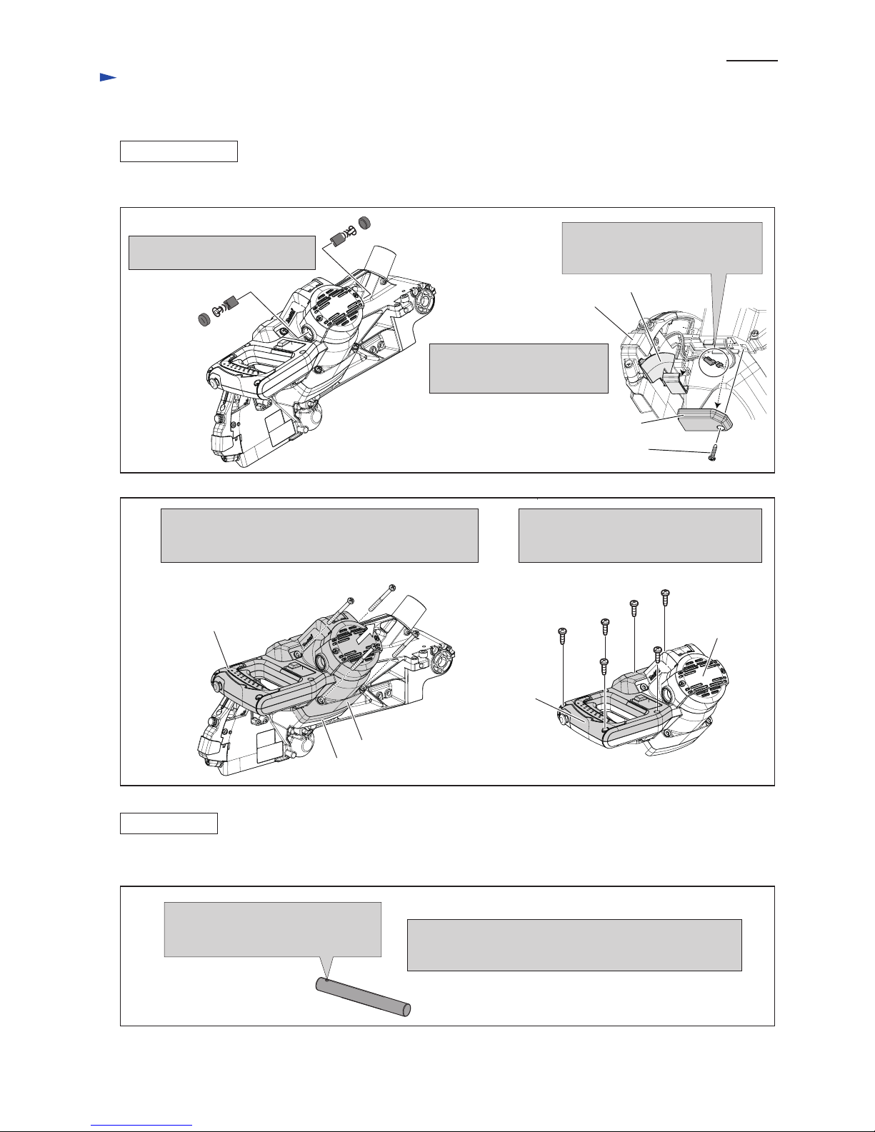
[1] NECESSARY REPAIRING TOOLS
[2] LUBRICATIONS
Code No. Description Use for
1R028 Bearing setting pipe 20-12.2 Mounting Retaining ring S-12
1R031 Bearing setting pipe 28-12.2 Mounting Helical gear 27
1R034 Bearing setting plate 12.2 Mounting Helical gear 27
1R036 Bearing setting plate 17.2 Mounting Helical gear 28
1R045 Gear extractor (large) Mounting / Removing Helical gear 14
1R207 45-degree set square Adjusting the bevel angle of Saw blade to 45 degree
1R208 90-degree set square Adjusting the bevel angle of Saw blade to 90 degree
1R217 Ring 22 Removing Helical gear 27
1R220 Ratchet head 27 Attachment for 1R254
1R222 Socket adapter Attachment for 1R254
1R232 Pipe 30 Mounting Helical gear 28
1R254 Torque wrench shaft 2 - 6 N.m Tightening Hex lock nut M10-17
1R269 Bearing extractor (small) Removing Ball bearings
1R291 Retaining ring S and R pliers Removing Retaining ring in Gear section
1R315 Laser beam positioning jig Adjusting Laser beam
253771-0 Flat washer 16 Adjusting Laser beam
782232-8 Box wrench 13 (standard accessory) Installing /Removing Blade Adjusting Blade position
134829-3 Socket 17-38 assembly Attachment for 1R254
1R346 Center attachment Attachment for 1R045
1R361 Bearing retainer wrench 14-23 Mounting / Removing Bearing retainer wrench 14-23
Apply Lubricants to the designated portions in order to protect parts and product from unusual abrasion.
Fig. 4
Item No. Description Portion to lubricate Lubricant Amount
a little
Cam Tip portion which contacts with 196 Leaf spring
Whole portion
Pin portion for receiving Stopper
180
161
190
Arm section
Arm complete
Portion where Arm’s hole without thread contacts
Rubber ring 9
195 Lock pin 8 Portion where Compression spring 6 contacts VG100 designated with
designated with
designated with
196 Leaf spring Surface where 195 and Compression spring 6 contact
197 Center shaft
161
190
Stopper
Retaining ring S-12
Flat washer 12
M10 Hex bolt as an axis of Lever 105
180
Pin portion of Arm for receiving Stopper
Lever 105
195
196
197
Makita grease SG.No.00
Compression
spring 6

[2] LUBRICATIONS (cont.)
Fig. 2
Item No.
Apply Makita grease SG.No.00 to the following portions designated with the black triangle to protect parts
and product from unusual abrasion.
Description Portion to lubricate
Center washer
4x16 Tapping screw
Center plate
Center cover
Safety cover A complete
Torsion Spring 45
Portion where Center cover contacts
Loop portion
Safety
cover B
102
97
102
97
103
103
Safety cover section
a. Portion where Pin 4 contacts
Upper fence
Lower fence
Guide fence
Lower fence L, R
b. Portion where Lower fence contacts
138
136
143
143
Pin 4
136 143
138
138
a
b
P 4/ 37
Repair
O ring 5
Rod 16
Sleeve 17 Drum portion
Pivot portion which contacts with Front arm
Drum portion
Whole portion
Stopper pin
149
152
Arm section
63
150
Knob 20
149
152
63
150
Front armTorsion spring 35
Blade case
Fig. 3
Fig. 4

P 5/ 37
Repair
Fig. 5
Fig. 6
Its teeth portion for smooth engaging with Spur gear 34
210
228 Miter lock plate
Turn base Rib which is on the opposite side of Turn base
207
Rack block
Slide plate Surface on which 207 Turn base moves
242 Base Hole for pivoting of Turn base
Surface where Cam portion of Grip 50 contacts.
248
Item No. Description Portion to lubricate Amount
Armature Gear shaft portion for smooth engaging with Spiral bevel gear 32
Teeth portion for smooth engaging with Helical gear 27
Motor and Blade case section
Turn base section
80 Helical gear 28
Link plate53
14
Link plate’s hole with which Rubber pin contacts
53
Blade case
Rubber pin
15g
8g
a little
a little
210
207
248
242
Linear bearing
box complete
Lock plate
Cam portion
of Grip 50
228
Blade case
Motor bracket
80
Helical gear 27
rib of Turn base Spur gear 43
Spiral bevel gear 32
14
[2] LUBRICATIONS (cont.)
Apply Makita grease SG.No.00 to the following portions designated with the black triangle to protect parts and product
from unusual abrasion.

[3] DISASSEMBLY/ASSEMBLY
[3]-1. Blade case, Motor section
DISASSEMBLING
Remove Strain reliefs from Arm complete and
Blade case by unscrewing 4x12 Tapping screw
(2pcs.).
Link plate
complete
Remove Link plate as illustrated below.
Blade case
Fig. 8
Fig. 7
Fig. 9
1. Remove Stop ring E-5, Flat washer 6 and Ring 6.
Link plate complete can be free from blade case.
2. Remove M6x20 Hex socket head bolt, Flat washer 6
and Ring 6. Link plate complete can be free from
Front arm.
Ring 6
Flat washer 6
Ring 6
Flat washer 6
Stop ring E-5
M6x20 Hex socket head bolt
Knob 20
Aligning notch B with Stopper pin, push Knob 20 toward the notch.
Blade case can be locked at starting position.
Remove M4x10 Pan head screw (2pcs.) for Guard as illustrated below
and then separate Guard section.
notch A: locking Blade case to
Base at 90 degrees
notch B: locking Blade case
at starting position
notch C: locking Blade case
at the lowest position
Blade case
Note: Refer to Fig. 7. The three notches on Blade case have
important role for disassembly / assembly.
(1) Disconnect the linkage of Blade case with Arm and Base
section by removing Strain relief and Link plate as
illustrated in Figs. 8 and 9.
notch B
Strain relief
4x12 Tapping screw
4x12 Tapping screw
Strain relief
P 6/ 37
Repair
Guard section
M4x10 Pan head screw
(2pcs.)

[3] DISASSEMBLY/ASSEMBLY
[3]-1. Blade case, Motor section (cont.)
DISASSEMBLING
Fig. 10
Correct Wrong
Fig. 11
Fig. 12
Sleeve 6
2. Holding Blade case by hand,
lift up it slowly until notch A
aligns with Stopper pin.
And then, push Knob 20.
1. Remove M5x18 Hex socket head bolt
and Sleeve 6. Then pull Knob 20
while holding Blade case by hand.
M5x18 Hex socket head bolt
3. Loosen M6x16 Hex socket head set
bolt for fixing Rod 16 so slightly that
Rod 16 can be pushed out smoothly
in the step of Fig. 9.
4. Loosen M6x20 Hex socket head bolt for
fixing Torsion spring 35 until the bolt
becomes free from force of the torsion
spring.
Knob 20
notch A
notch B
notch B
Socket wrench 10
Blade case
Blade case, Torsion spring 35 and Sleeve 17
can be removed from Front arm as illustrated
above.
Sleeve 17
Torsion spring 35
Remove Rod 16 by striking the Socket wrench 10 in the same
direction in which Knob 20 is pushed. Fig. 12 is the reason
why Rod 16 has to be removed.
Knob 20 Direction for
pushing Knob 20
Rod 16
Blade case
The inside of Sleeve 17 is scraped by burr on Rod 16,
if the Rod is pulled off in the direction designated with
black arrow.
burr produced by pressure of the Hex
socket head set bolt
burr produced by pressure of the
Hex socket head set bolt
M6x16 Hex socket
head set bolt
M6x16 Hex socket
head set bolt
Front arm
Sleeve 17 Sleeve 17
Blade case
Rod 16
Rod 16
Front arm Front arm
Knob 20
Knob 20
Knob 20
The inside of Sleeve 17 is not scraped by burr
on Rod 16, because the burr portion is not passed
through Sleeve 17.
(2) Remove Rod 16 as illustrated in Figs. 10 and 11. Blade case can be separated from Arm and Base section.
P 7/ 37
Repair

[3] DISASSEMBLY/ASSEMBLY
[3]-1. Blade case, Motor section (cont.)
DISASSEMBLING
ASSEMBLING
4x18 Tapping screw
1. Remove Carbon brushes from
Motor housing.
Lead cover holder
Blade case
(3) Motor section can be disassembled from Blade case as illustrated in Figs. 13 and 14.
Fig. 13
Fig. 14
Fig. 15
2. Remove 4x18 Tapping screw,
Lead cover holder and Lead
cover.
Remove M6x80 Pan head screw (4pcs). Motor housing,
Motor bracket and Handle section can be separated from
Blade case.
3. Disconnect connectors of Laser
circuit from that of Power supply
circuit.
M6x80 Pan head screw (4pcs.)
Motor bracket
(1) Make the drum portion of Rod 16 smooth by filing and applying grease.
Motor housing
Handle section
6x18 Tapping screw (6pcs.)
Remove Handle cover by unscrewing
6x18 Tapping screw (6pcs.). The electrical
parts in Handle can be replaced.
Motor housing
Handle cover
Lead cover
Before assembling, remove burr by scraping with file,
and apply grease to the drum portion for smooth assembling
Rod 16 into Sleeve 17.
Rod 16 removed in Fig.11 has burr
at the point on which Hex socket head
set bolt puts pressure.
P 8/ 37
Repair

[3] DISASSEMBLY/ASSEMBLY
[3]-1. Blade case, Motor section (cont.)
ASSEMBLING
(2) Assemble Rod 16 which functions as an axis for Blade case in the order of Figs. 16 17 and 18.
Fig. 16
Fig. 17
Fig. 18
Sleeve 17
Insert Sleeve 17 into
Torsion spring 35.
Torsion spring 35
Front arm
Blade case
Groove for setting the tail of
Compression spring 35
Knob 20
Aligning notch C with Stopper pin, push
Knob 20 toward the notch to lock Blade case
at the lowest position.
notch C
Insert Rod 16 from the left hole of Front arm to the left hole of Blade
case completely until the top end of Rod 16 is flush with the inside of
Blade case as illustrated below.
Knob 20
Put Blade case onto Front arm
while aligning the hole to that of
Front arm in order to pass Rod 16
smoothly in the step of Fig. 15.
Blade case
Front arm
right hole of
Front arm
right hole of
Front arm
right hole of
Blade case
left hole of
Blade case
Aligning notch A with Stopper pin,
push Knob 20 toward the notch to keep
90 degrees between Blade case and Base.
tail
Put one of the tail of Torsion spring 35
into the groove of Front arm.
Knob 20
top end of
Rod 16
top end of Rod 16
Push Rod 16 until the top end reaches
the surface of Front arm through Blade
case and Front arm as illustrated above.
Rod 16
(3) Tighten Torsion spring 35 with M6x20 Hex socket head bolt until the Hex socket head bolt is seated on Blade case.
And tighten Rod 16 with M6x16 Hex socket head set bolt. Refer to right illustration in Fig. 10.
P 9/ 37
Repair
left hole of Front arm
inside of
Blade case

[3] DISASSEMBLY/ASSEMBLY
[3]-1. Blade case, Motor section (cont.)
ASSEMBLING
DISASSEMBLING
Fig. 19
Fig. 20
Fig. 21
Handle Pressing Handle toward the rib of Blade case,
assemble it to Motor housing by tightening
with 4x18 Tapping screws.
Pressing Lead cover holder toward Lead cover,
assemble it to Handle complete by tightening
with 4x18 Tapping screw.
Lead cover holder
rib of
Blade case
Lead cover
4x18
Tapping screw
Motor housing
(4) When assembling Motor section to Blade case, do as illustrated in Fig. 19.
[3]-2. Gear section (Spiral bevel gear 32, Helical gear 14, Helical gear 27, Helical gear 28)
(1) Lock Blade case at starting position as illustrated in Fig. 8. And remove Link plate as illustrated in Fig. 9.
(2) Remove Motor housing and Handle section as illustrated in Figs. 13 and 14. However, no need to remove Handle cover.
(3) Tilt Blade case in the direction of Motor housing at 45 degrees to prevent Gear portion from falling off. And then,
separate Gear section from Blade case as illustrated in Figs. 20 and 21.
1R361
Turn Bearing retainer 14-23 with 1R361 counterclockwise.
Bearing retainer can be removed from Blade case.
M5 Hex nut
M5x16 Countersunk head screw (2pcs.)
M5x16
Pan head
screw (3pcs.)
Remove the Screws illustrated
below and Bearing retainer 51.
Insert slotted screwdrivers between
Blade case and Bearing box and
lift up Bearing box as illustrated
below.
Gear section can be separated from
Blade case together with Bearing box.
Bearing
retainer 14-23
M5 Hex nut
While pressing Shaft lock, remove M5 Hex nut
with Socket bit 8.
Spring washer 5
Flat washer 5
Helical gear 28
Baring box
shaft of
Helical
gear 14 Helical gear 27
Spiral bevel
gear 32
Bearing
retainer 51
P 10/ 37
Repair

P 11/ 37
Repair
[3] DISASSEMBLY/ASSEMBLY
[3]-2. Gear section (Spiral bevel gear 32, Helical gear 14, Helical gear 27, Helical gear 28)
(cont.)
DISASSEMBLING
Fig. 22
Fig. 23
Fig. 24
(4) Spiral bevel gear 32 and Helical gear 14 can be disassembled as illustrated in Figs. 22 and 23.
(5) Helical gear 27 and Gear shaft can be disassembled as illustrated in Fig. 24.
Woodruff
key 4
Grease
holder
Shaft of
Helical gear 14
1R045
1R346
Unscrew 4x12 Tapping screws and remove
Grease holder from Bearing box.
4x12
Tapping screw
1. Remove Ball bearing 608DDW with
1R269 from the shaft of Helical gear 14.
2. Remove Retaining ring S-12 with
1R291 from the shaft of Helical gear 14.
Rubber
washer 12 Flat washer 12
Spiral bevel gear 32
Helical gear 14
Ball bearing
6000ZZ
Helical gear 27
Gear shaft
Steel ball 4
Disassemble Helical gear 27 from Bearing box.
Remove Ball bearing 6000ZZ from Gear shaft with 1R269.
And then, take out Steel ball 4 from the Gear shaft.
Putting the Helical gear 27 on 1R217,
remove Gear shaft by pressing with
arbor press.
1R269
1R217
Bearing box
Ball bearing
608DDW
Ball bearing 608DDW
Ball bearing 608DDW can be
removed by pressing from Grease
holder side to Bearing retainer side.
Helical gear 27

[3] DISASSEMBLY/ASSEMBLY
[3]-2. Gear section (Spiral bevel gear 32, Helical gear 14, Helical gear 27, Helical gear 28)
(cont.)
DISASSEMBLING
ASSEMBLING
(6) Helical gear 28 and Spindle can be disassembled as illustrated in Figs. 25.
(1) Assemble Helical gear 28 section to Bearing box as illustrated in Fig. 26. And then, assemble Retaining ring S-15
and Ball bearing 608DDW to Spindle. Refer to Fig. 25.
(2) Assemble Helical gear 27 section to Bearing box as illustrated in Fig. 27.
Fig. 25
Ball bearing
608DDW
Disassemble Ball bearing 608DDW with 1R269. And remove
Retaining ring S-15 from Spindle with 1R291.
Receiving Ball bearing 6002DDW with
the table of Arbor press, press down
Spindle with Arbor press.
Bearing box
1R269
Retaining
ring S-15
1R291
Spindle
Spindle
Ball bearing
6002DDW
Helical gear 28
Fig. 26
Fig. 27
Spindle
Helical gear 28
Helical
gear 28
1R232
1R036
Ball bearing
6002DDW
Rim portion has
to be faced to
Bearing box side.
Bearing box
Gear shaft
Steel ball 4
Helical
gear 27
The convex side has
to be faced to Gear shaft
end on which Steel ball 4
is mounted.
Convex side
Assemble Helical gear 27, Ball bearing 6000ZZ and Steel ball 4 to Gear shaft.
And then, assemble the Helical gear 27 section to Bearing box.
Ball bearing
6000DDW
P 12/ 37
Repair

[3] DISASSEMBLY/ASSEMBLY
[3]-2. Gear section (Spiral bevel gear 32, Helical gear 14, Helical gear 27, Helical gear 28)
(cont.)
ASSEMBLING
Fig. 28
Fig. 29
(3) Assemble Helical gear 14 to Bearing box as illustrated in Fig. 28.
(4) After mounting Grease holder, set Spiral bevel gear 32 to the shaft of Helical gear 14 as illustrated in Fig. 29.
Spindle
Pressfit Ball bearing 608DDW to Bearing box.
Tighten provisionally Bearing retainer 14-23.
Assemble Helical gear 14 with 1R045 and R346.
Bearing retainer 14-23
Ball bearing 608DDW Helical gear 14
Tighten Grease holder
with 4x12 Tapping screws.
Helical gear 27
4x12 Tapping screw (2pcs.)
Grease
holder
Woodruff key 4
Spiral bevel gear 32
While fixing Woodruff key 4 by finger, align the notch of Spiral bevel
gear to the Woodruff key and push down the Gear.
Spiral bevel gear 32 can be assembled to the shaft of Helical gear 14.
Helical gear 28
1R346
1R045
P 13/ 37
Repair

[3] DISASSEMBLY/ASSEMBLY
[3]-2. Gear section (Spiral bevel gear 32, Helical gear 14, Helical gear 27, Helical gear 28)
ASSEMBLING
Fig. 30
Fig. 31
(5) Secure Spiral bevel gear 32 with Retaining ring S-12 as illustrated in Fig. 30.
Inserting Rubber washer 12 between
Flat washers 12, mount these washers
to the shaft of Helical gear 14. And put
Retaining ring S-12 onto Flat washer 12.
Rubber washer 12
Flat washer 12
Retaining ring S-12 1R028
Put Bearing box on 1R036.
Applying 1R028 to Retaining ring S-12,
press the 1R028 with Arbor press.
Retaining ring S-12 can be fit to the groove on
the shaft of Helical gear 14.
1R036
Retaining ring
S-12
(6) Mount the assembled Gear section to Blade case by fastening with M5x16 Pan head screw (3pcs.).
And fasten Bearing retainer 51 with M5x16 Countersunk head screw (2pcs.). Refer to Fig. 21.
(7) Mount Flat washer 5 and Spring washer 5 to the shaft of Helical gear 14. And tighten M5 Hex nut with Socket wrench 8
while pressing Shaft lock. Refer to the right illustration in Fig. 20.
(8) Referring to Fig. 20, firmly tighten Bearing retainer 14-23 which has been provisionally tightened in the step in Fig. 28.
Use 1R361 for tightening the Bearing retainer.
(9) Mount Motor housing to Blade case. Refer to the left illustration in Fig. 14 and the left illustration in Fig. 13.
(10) Assemble Link plate complete. Refer to Fig. 9.
[3]-3. Safety lock mechanism
DISASSEMBLING
M4x10 Pan
head screw (2pcs.)
Lock lever
Remove Lock lever from Rod 8 by
unscrewing M4x10 Pan head screws.
Remove Torsion spring 8 from
Rod 8.
Remove Rod holder from Blade case.
Pull off Rod 8 from Rod holder.
Rod 8
Torsion spring 8
Torsion spring 8
Rod 8
Disassemble as illustrated in Fig. 31.
Rod 8
Rod holder
4x16 Tapping screw (2pcs.)
Rod 8 Stop ring E-6Rod holder
P 14/ 37
Repair

[3] DISASSEMBLY/ASSEMBLY
[3]-3. Safety lock mechanism
ASSEMBLING
Fig. 32
Torsion spring 8
rib of
Blade case
rod 8
Rod 8
Rod holder Blade case
Stop ring E-6
(1) Assemble Safety lock mechanism as illustrated in Fig. 32.
(2) Adjust the position of Lock lever as illustrated in Fig. 33.
Insert Rod 8 into Rod holder,
and set Rod holder to Blade case.
While pushing Rod holder toward
the rib of Blade case, secure Rod
holder with 4x16 Tapping screw (2pcs.).
And assemble Torsion spring 8.
Pretighten M4x10 Pan head screw
(2pcs.) to fasten Lock lever and Rod 8.
M4x10 Pan
head screw (2pcs.)
4x16 Tapping
screw (2pcs.)
Fig. 33
Lock lever
Lock lever
Lock lever
Safety cover B
After leaving a 2 up to 3mm clearance between Lock lever
and Safety cover B, secure Lock lever by tightening M4x10
Pan head screw (2pcs.).
Safety
cover B
P 15/ 37
Repair
2 - 3mm

[3] DISASSEMBLY/ASSEMBLY
[3]-4. Safety cover A
ASSEMBLING
Fig. 35
(1) Assemble Safety cover A section as illustrated in Fig. 34. And then mount the Safety cover A section to Safety cover B
as illustrated in Fig. 35.
(2) Mount the Safety cover section to Blade case complete as illustrated in Fig. 36.
Fig. 36
Tighten Center cover with
Hex flange head bolt M8x12.
But reserve the allowance
to move the Center cover.
Move Center cover until its
protrusion touches the flange of
M8x12 Hex flange head bolt.
Tighten Center cover with
Hex flange head bolt firmly.
4x12 Tapping
Screw (3pcs.)
Safety cover A
Mount the Safety cover A section
to the Safety cover B by tightening
with 4x12 Tapping screw (3pcs.).
Safety cover B
Center cover
Fig. 34
After applying grease to Torsion
spring 45, set the tails to Safety
cover A as illustrated below.
Torsion spring 45
Put Center washer on the Torsion
spring 45, fitting its five holes
to the five bosses of Safety cover A.
Apply Grease to this portion which
contacts the hole of Center cover .
After mounting Center cover,
assemble Center plate, fitting
its five holes to five bosses of
Safety cover A .
Center
washer
Boss
(5points)
Center
cover
Center plate
Safety cover A
P 16/ 37
Repair

[3] DISASSEMBLY/ASSEMBLY
[3]-5. Turn Base, Base
DISASSEMBLING
ASSEMBLING
Fig. 38
(1) Remove the parts from Turn base and Base as illustrated in Fig. 37.
(2) Removing M8x45 Hex bolt, separate Turn base section from Base as illustrated in Fig. 38.
Fig. 39
Fig. 37
1. Remove Upper fence, Lower
fence, Guide fence and Kerf
board.
Lever 45 (2pcs.)
Upper fence (2pcs.)
Kerf board
Grip 50
Lower fence (2pcs.)
Guide fence
Slide plate
Apply Grease to Slide plate and the center hole
of Base before assembling Turn base section.
Assemble Turn base section as illustrated in Fig. 39. And then, take the disassembling step in reverse. Refer to Fig. 37.
Miter scale plate
3. Remove Miter scale plate from Base by
unscrewing 4x12 Tapping screw (3pcs.)
2. Turning Grip 50 clockwise at
90 degrees, move Turn base to
the direction designated with
black arrow until it stops.
Turn base
section
Remove M8x45 Hex bolt with
Socket wrench 13.
And remove Flat washer 8.
M8x45 Hex bolt
Flat washer 8
Base
Turn base section has to be tightened with M8x45 Hex bolt
so that it can smoothly turn without wobbling.
Base
While pressing down Lock
lever, fit Turn base section
to Base.
Lock lever
While pressing down Lock
lever, remove Turn base
section from Base.
Lock lever
Flat washer 8
M8x45 Hex bolt
P 17/ 37
Repair

[3] DISASSEMBLY/ASSEMBLY
[3]-6. Positive lock mechanism of Turn base
DISASSEMBLING
ASSEMBLING
Fig. 43
(1) Remove Stop ring E-7. (Fig. 40)
Grip 50, Compression spring 11, Flat washer 10 and Cam
can be removed.
(2) Remove M6x14 H.S.Binding head screw then remove
Miter lock plate in the direction designated with black
arrow. (Fig. 41)
(3) Remove CT 4x16 Tapping screw (2pcs.) and Lock lever
plate. (Fig. 42)
(4) Push Lock pin 6 in the direction designated with black
arrow and pick up Lock lever in the direction designated
with gray arrow. (Fig. 43)
(5) Remove Pin 3 from Lock pin 6, then pull out Lock pin 6 in
the direction designated with black arrow. (Fig. 44)
Fig. 45
Fig. 40
Fig. 41 Fig. 42
Fig. 44
Slide plate
Apply Grease to Slide plate and the center hole
of Base before assembling Turn base section.
Assemble Turn base section as illustrated in Fig. 45. And then, take the disassembling step in reverse. Refer to Fig. 37.
Turn base section has to be tightened with M8x45 Hex bolt
so that it can smoothly turn without wobbling.
Base
While pressing down Lock
lever, fit Turn base section
to Base.
Lock lever
Flat washer 8
M8x45 Hex bolt
P 18/ 37
Repair
Stop ring E-7
Compression spring 11
Flat washer 10
Grip 50
Turn base
Groove for Stop ring E-7
Cam
Turn base
Pin
Lock pin 6Lock lever
Compression spring 13
Miter lock plate
Lock lever plate CT4x16
Tapping screw
(2pcs.)
Miter lock plate
Miter lock plate can be pulled out
without removing Pin.
M6x14 H.S.Binding
head screw
Lock pin 6Pin 3Compression
spring 6

[3] DISASSEMBLY/ASSEMBLY
[3]-6. Positive lock mechanism of Turn base (cont.)
[3]-7. Assembling of Square rod complete
[3]-8. Stopper pin
ASSEMBLING
DISASSEMBLING
ASSEMBLING
Note: Assemble Grip 50 to Miter lock plate as illustrated in Fig. 46
so that the notch of Cam portion faces the upper side.
Match both ends of Square rod complete with
the notches of Arm holder complete on condition
that the notches are closest position to the center
of Turn base, and tighten M5x30 Hex bolt (2pcs.)
as illustrated in Fig. 47.
Note: Face the concave of Square rod complete to the
center of Turn base.
1) Push Knob 20 to lock Blade case at highest position
in the moving range.
Then remove M6x20 Hex socket head bolt for
securing Link plate. (Fig. 48)
2) Lower Blade case slightly to hold Stopper pin, turn
Knob 20 counterclockwise a little.
Note: Do not remove Knob 20, or Stopper pin will not
be pulled.
3) Remove Blade case section according to the step
shown in clause [3]-1.
4) Remove Knob 20 from Stopper pin, and then pull out
Stopper pin in the direction designated with black
arrow in Fig. 48.
Take the disassembling step in reverse.
Note: Apply Makita grease SG No.00 to O ring 5 that
is fit into Stopper pin. Refer to Fig. 1.
Square rod
complete
center of
Turn base
notch of Cam portion
of Grip 50
Miter lock plate
Fig. 46
Fig. 47
Fig. 48
P 19/ 37
Repair
M5x30 Hex bolt (2pcs.)
notches of
Arm holder
complete
threaded holes of
Arm holder complete
Arm holder complete
Link plate
complete
Knob 20 Stopper pin
M6x20 Hex
socket head bolt
Flat washer 6
Ring 6

[3] DISASSEMBLY/ASSEMBLY
[3]-9. Front arm section
DISASSEMBLING
ASSEMBLING
DISASSEMBLING
Refer to Fig. 49.
1) Loosen M6x8 Hex. socket set screw (2pcs.) on Pipe
holder and remove Pipe holder.
2) Loosen M6x18 Thumb screw and pull out Front
arm complete straightly in the direction designated with
white arrow to prevent the pipes from being stuck.
Take the disassembling step in reverse.
1) Loosen Lever 105 by turning counterclockwise. (Fig. 50)
2) Remove M4x10 Pan head screw and then remove Lever 105. (Fig. 51)
3) Remove M10 Hex bolt and Flat washer 10. (Fig. 51)
4) Remove M10-17 Hex lock nut using Box wrench 17.
Flat washer 10 (2pcs.) and Thrust needle cage 1024 can be removed as illustrated in Fig. 52.
5) Remove Arm section from Arm holder complete. (Fig. 53)
6) Remove Retaining ring S-12 from the groove on Arm using 1R291.
Stopper, Flat washer 12 and Torsion spring 14 can be removed. (Fig. 54)
Remove CT 4x16 Tapping screw (3pcs.) Pointer and Arm cover. (Fig. 54)
Fig. 49
Fig. 50
Fig. 53
Fig. 51 Fig. 52
Fig. 54
P 20/ 37
Repair
M6x8 Hex. socket
set screw (2pcs.)
Pipe holder
Front arm
complete
Pipes of Front arm complete
M6x18 Thumb screw
[3]-10. Arm complete, Arm holder
Lever 105
Arm section
Arm cover
Pointer
Arm holder complete
Groove on Arm for
fitting Retainer ring S-12 Retainer ring S-12
Flat washer 12
Torsion
spring 14
Stopper
CT 4x16
Tapping screw
(3pcs.)
Lever 105
M4x10 Pan
head screw
M10 Hex bolt
Flat washer 10
M10-17
Hex lock nut
Thrust needle cage 1024
Flat washer 10
Other manuals for LS1016
12
This manual suits for next models
1
Table of contents
Other Makita Saw manuals

Makita
Makita LH1200FL User manual

Makita
Makita LS002G User manual

Makita
Makita LS0714L User manual

Makita
Makita LS0815F User manual

Makita
Makita SP001G User manual

Makita
Makita LS003G User manual

Makita
Makita 5008MG User manual

Makita
Makita LS0714FL User manual

Makita
Makita LS1214 User manual

Makita
Makita UC100D User manual

Makita
Makita DLS714 User manual

Makita
Makita XBP01 User manual

Makita
Makita DJR183 User manual

Makita
Makita DPB180RTE User manual

Makita
Makita 5800NB User manual

Makita
Makita LC1230 User manual

Makita
Makita JR002GZ User manual

Makita
Makita 5104S User manual

Makita
Makita JR3070CTH User manual

Makita
Makita UC100DWA User manual