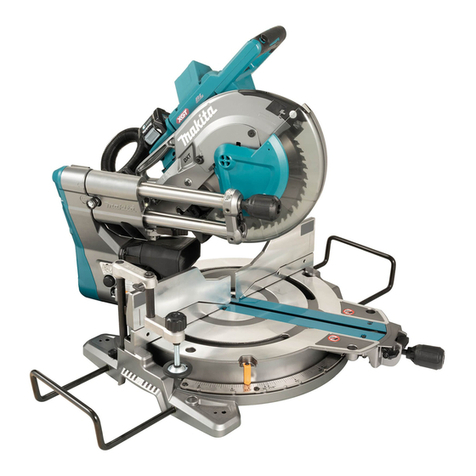
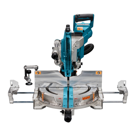
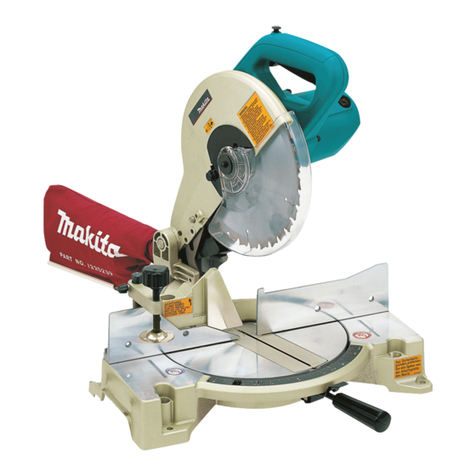
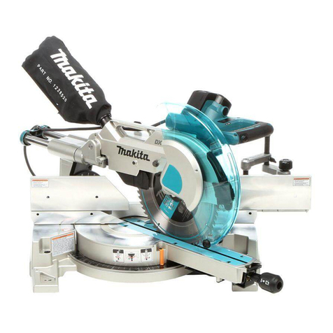
Makita LH1201FL User manual

1
GB Table Top Miter Saw INSTRUCTION MANUAL
UA Верстатна торцювальна пила ІНСТРУКЦІЯ ЗЕКСПЛУАТАЦІЇ
PL Ukośnica/ pilarka stołowa INSTRUKCJA OBSŁUGI
RO
Ferăstrău pentru tăieri oblice cu montare pe masă
MANUAL DE INSTRUCŢIUNI
DE Universal-Kapp-und Gehrungssäge BEDIENUNGSANLEITUNG
HU Asztali gérvágó HASZNÁLATI KÉZIKÖNYV
SK Stolová píla na zrezávanie NÁVOD NA OBSLUHU
CZ Stolní pokosová pila NÁVOD K OBSLUZE
LH1201FL

2
1
1 012175
2
1
3
2 012176
2
3
4
6
5
1
3 012177
1
2
3
4 012178
1
2
4
3
5 012179
1
6 015123
1
3
2
7 012181
1
32
8 012182
1
9 012183
1
10 012184
1
12 012188
5
1
2
4
3
13 012189
1
3
2
4
14 012190
2
3
1
15 012191
1
2
11 015680

3
1
2
16 012192
12
3
4
17 012193
1
2
3
6
45
18 012194
1
20 012196
1
2
3
21 012197
5
3
1
4
2
22 015124
1
23 012199
5
4
31
6
2
24 015125
AB CD
1
2
3
25 012201
1
364
2
5
26 012202
1
1
27 012203
2
3
1
28 012204
32
1
29 012205
1
23
30 012206
1
4-5mm
2
3
19 015681

4
1
2
31 012207
1
2
32 012208
1
33 012209
12
34 001549
1
35 015064
4
3
1
2
65
36 015126
1
2
3
4
37 015127
1
38 015128
1
39 015129
1
2
3
4
5
40 001844
1
2
3
41 015130
1
2
15mm
10mm
14mm
40mm
70mm
300mm
140mm
42 005565
1
43 012214
1
44 015131
1
2
45 012216

5
1
46 012217 47 012218
1 1
48 015132
1
2
3
49 015133
13
2
50 012221
1
2
3
51 010798
1
2
3
4
52 012222
4
1
2
3
53 012223 54 007834
1
2
55 012227

6
ENGLISH (Original instructions)
Explanation of general view
1-1. Bolt
2-1. Lower blade guard A
2-2. Top blade guard
2-3. Lower blade guard B
3-1. Lower blade guard A
3-2. Top blade guard
3-3. Screw
3-4. Hex bolt
3-5. Handle
3-6. Lever
4-1. Top surface of turn base
4-2. Periphery of blade
4-3. Guide fence
5-1. Pointer
5-2. Lock lever
5-3. Grip
5-4. Miter scale
6-1. Lever
7-1. Lever
7-2. Bevel scale
7-3. Pointer
8-1. Power switch
8-2. Lamp switch
8-3. Laser switch
9-1. Lamp
10-1. Switch for laser
11-1. Lever
11-2. Knob
12-1. Stopper pin
13-1. Lower blade guard A
13-2. Lower blade guard B
13-3. Top table
13-4. Motor housing
13-5. Handle
14-1. Center cover
14-2. Socket wrench
14-3. Hex bolt
14-4. Lower blade guard A
15-1. Socket wrench
15-2. Shaft lock
15-3. Hex bolt
16-1. Blade guard B
16-2. Saw blade
17-1. Blade case
17-2. Arrow
17-3. Saw blade
17-4. Arrow
18-1. Hex bolt
18-2. Outer flange
18-3. Saw blade
18-4. Inner flange
18-5. Spindle
18-6. Ring
19-1. Top blade guard
19-2. Riving knife
19-3. Knob
20-1. Hex bolts
21-1. Blade width
21-2. Riving knife
21-3. Hex bolt
22-1. Rip fence holder
22-2. Guide rail on the top table
22-3. Clamping screw (A)
22-4. Clamping screw (B)
22-5. Rip fence
23-1. Rip fence
24-1. Rip fence
24-2. Rip fence holder
24-3. Line to be aligned with
24-4. Saw blade
24-5. Top table
24-6. Workpiece
25-1. Rip fence
25-2. Rip fence holder
25-3. Saw blade
26-1. Rip fence
26-2. Rip fence holder
26-3. Square nut
26-4. Clamp screw (A)
26-5. Clamp screw (B)
26-6. Washer
27-1. Scale
28-1. Rip fence
28-2. Rip fence holder
28-3. Adjusting screw
29-1. Rip fence
29-2. Saw blade
29-3. Top blade guard
30-1. Dust nozzle
30-2. Dust bag
30-3. Fastener
31-1. Dust bag
31-2. Fastener
32-1. Vacuum cleaner
32-2. Blade cover
33-1. Vacuum cleaner
34-1. Support
34-2. Turn base
35-1. Sub-fence
36-1. Vise arm
36-2. Vise rod
36-3. Guide fence
36-4. Holder
36-5. Vise knob
36-6. Screw
37-1. Vise knob
37-2. Projection
37-3. Vise shaft
37-4. Base
38-1. Vise
39-1. Vise
40-1. Vise
40-2. Spacer block
40-3. Guide fence
40-4. Aluminum extrusion
40-5. Spacer block
41-1. Blade cover
41-2. Small boss
41-3. Sub-fence
42-1. Face/edge parallel
42-2. Hole(7 mm in diameter)
43-1. Clamping screw
44-1. Push stick
45-1. Auxiliary fence
45-2. Push block
46-1. Stopper pin
48-1. Hex bolt
49-1. Triangular rule
49-2. Grip
49-3. Guide fence
50-1. Turn base
50-2. Lever
50-3. 0 ゚adjusting bolt
51-1. Triangular rule
51-2. Saw blade
51-3. Top surface of turn base
52-1. Arm
52-2. Bevel scale
52-3. Pointer
52-4. Turn base
53-1. Lever
53-2. Arm
53-3. Pointer
53-4. 45 ゚bevel angle adjusting bolt
55-1. Screwdriver
55-2. Brush holder cap

7
SPECIFICATIONS
Model LH1201FL
Blade diameter 305 mm
Blade body thickness 1.9 mm or less
Hole diameter
For all countries other than European countries 25.4 mm
For European countries 30 mm
Max. Cutting capacities (H x W) with blade 305 mm in diameter in the miter saw mode
Miter angle
Bevel angle 90° 45° (left to right)
95 mm x 155 mm 95 mm x 110 mm
90° 62 mm x 200 mm 62 mm x 135 mm
64 mm x 155 mm 64 mm x 65 mm
45° 40 mm x 200 mm 40 mm x 85 mm
Max. Cutting capacities at 90° in the table saw (bench saw mode) 52 mm
No load speed (min-1) 3,800
Laser Type Red Laser 650 nm, 1 mW (Laser Class 2)
Table size (W x L) 307 mm x 465 mm
Dimensions (L x W x H) 610 mm x 535 mm x 692 mm
Net weight 20.9 kg
Safety class /II
• Due to our continuing program of research and development, the specifications herein are subject to change without notice.
• Specifications may differ from country to country.
• Weight according to EPTA-Procedure 01/2003
END292-5
Symbols
The following show the symbols used for the equipment.
Be sure that you understand their meaning before use.
・Read instruction manual.
・DOUBLE INSULATION
・To avoid injury from flying debris, keep
holding the saw head down, after
making cuts, until the blade has come
to a complete stop.
・
When using the tool in the miter saw mode,
secure the top table at the topmost position
so that the saw blade never protrudes from
the top surface of the top table.
・Do not place hand or fingers close to
the blade.
・For your safety, remove the chips,
small pieces, etc. from the table top
before operation.
・
Always set SUB-FENCE to left position
when performing left bevel cuts. Failure to
do so may cause serious injury to operator.
・Never look into the laser beam. Direct
laser beam may injure your eyes.
・Only for EU countries
Do not dispose of electric equipment
together with household waste
material!
In observance of the European
Directive, on Waste Electric and
Electronic Equipment and its
implementation in accordance with
national law, electric equipment that
have reached the end of their life must
be collected separately and returned to
an environmentally compatible
recycling facility.
ENE060-1
Intended use
The tool is intended for accurate straight cutting and
(only when used as a miter saw on the lower table)
miter cutting in wood.
ENF002-2
Power supply
The tool should be connected only to a power supply of
the same voltage as indicated on the nameplate, and
can only be operated on single-phase AC supply. They
are double-insulated and can, therefore, also be used
from sockets without earth wire.
ENG905-1
Noise
The typical A-weighted noise level determined
according to EN61029:
Model LH1201FL 220V - 240V
Sound pressure level (LpA) : 93 dB (A)
Sound power level (LWA) : 106 dB (A)
Uncertainty (K) : 3 dB (A)

8
Model LH1201FL 110V
Sound pressure level (LpA) : 95 dB (A)
Sound power level (LWA) : 108 dB (A)
Uncertainty (K) : 3 dB (A)
Wear ear protection
ENH003-15
For European countries only
EC Declaration of Conformity
Makita declares that the following Machine(s):
Designation of Machine:
Table Top Miter Saw
Model No./ Type: LH1201FL
Conforms to the following European Directives:
2006/42/EC
They are manufactured in accordance with the following
standard or standardized documents:
EN61029
The technical file in accordance with 2006/42/EC is
available from:
Makita, Jan-Baptist Vinkstraat 2, 3070, Belgium
31.7.2015
000331
Yasushi Fukaya
Director
Makita, Jan-Baptist Vinkstraat 2, 3070, Belgium
GEA010-1
General Power Tool Safety
Warnings
WARNING Read all safety warnings and all
instructions.
Failure to follow the warnings and instructions
may result in electric shock, fire and/or serious injury.
Save all warnings and instructions for
future reference.
ENB088-5
TABLE TOP MITER SAW SAFETY
WARNINGS
FOR BOTH MITER SAW MODE AND TABLE SAW
(BENCH SAW) MODE
1. Check the blade carefully for cracks or
deformation before operation.
Replace damaged blade immediately.
2.
Do not operate saw without guards and riving knife
in place, especially after a mode change. Check
blade guards for proper closing before each use.
Do not operate saw if blade guards do not move
freely and close instantly. Never clamp or tie the
blade guards into the open position. Any irregular
operation of the blade guards should be corrected
immediately.
3. Use only saw blades specified by the
manufacturer and which conform to EN847-1.
The groove width of the cut must be thicker
than the riving knife and the blade body must
be thinner than the riving knife.
4. Do not use saw blades manufactured from
high speed steel.
5. Wear eye protection.
6. Wear hearing protection to reduce the risk of
hearing loss.
7. Wear gloves for handling saw blades (saw
blades shall be carried in a holder wherever
practicable) and rough material.
8. Connect the tool to a dust collecting device
when sawing.
9.
Always store the push-stick when it is not in use.
10. Keep the floor area around the tool level well
maintained and free of loose materials e.g.
chips and cut-offs.
11. The operator is adequately trained in the use,
adjustment and operation of the tool.
12. Stop and unplug the saw when unattended.
13. To reduce the emitted noise, always be sure
that the blade is sharp and clean.
14. Use only saw blades that are marked with a
maximum speed equal to or higher than the
no load speed marked on the tool.
15. When the tool is fitted with a laser or LED, do
not replace the laser or LED with a different
type. Ask an authorized service center for repair.
16. Never remove any cut-offs or other parts of
the workpiece from the cutting area whilst the
tool is running with an unguarded saw blade.
17. The tool should not be used for slotting,
rebating or grooving.
18. Before carrying the tool, always cover the
upper part of the saw blade by the top guard
and secure all moving portions. When lifting
or carrying the tool, do not use the guard as a
carrying handle.
19.
Clean and be careful not to damage the spindle,
flanges (especially the installing surface) and hex
bolt before or when installing the blade. Damage to
these parts could result in blade breakage. Poor
installation may cause vibration/wobbling or
slippage of the blade. Use only flanges specified
for this tool.
20. Always use accessories recommended in this
manual. Use of improper accessories such as
abrasive cut-off wheels may cause an injury.
21. Select the correct saw blade for the material
to be cut.
22. Do not cut metal objects such as nails and
screws. Inspect for and remove all nails,
screws and other foreign material from the

9
workpiece before operation.
23. Knock out any loose knots from workpiece
BEFORE beginning to cut.
24. Do not use the tool in the presence of
flammable liquids or gases.
25.
For your safety, remove the chips, small pieces,
etc. from the work area and table top before
plugging the tool and starting operation.
26. Keep hands and make your bystander and
yourself position out of path of and not in line
with saw blade. Avoid contact with any
coasting blade. It can still cause severe injury
and never reach around saw blade.
27. Be alert at all times, especially during
repetitive, monotonous operations. Do not be
lulled into a false sense of security. Blades
are extremely unforgiving.
28. Make sure the shaft lock is released before
the switch is turned on.
29. Before using the tool on an actual workpiece,
let it run for a while. Watch for vibration or
wobbling that could indicate poor installation
or a poorly balanced blade.
30.
Wait until the blade attains full speed before cutting.
31. Stop operation immediately if you notice
anything abnormal.
32. Turn off tool and wait for saw blade to stop
before moving workpiece or changing
settings.
33. Unplug tool before changing blade, servicing
or not in use.
34. Some dust created from operation contains
chemicals known to cause cancer, birth
defects or other reproductive harm. Some
examples of these chemicals are:
−lead from lead-based-painted material and,
−arsenic and chromium from chemically-
treated lumber.
Your risk from these exposures varies,
depending on how often you do this type of
work. To reduce your exposure to these
chemicals: work in a well ventilated area and
work with approved safety equipment, such as
those dust masks that are specially designed
to filter out microscopic particles.
35.
Even when the tool is used as prescribed it is not
possible to eliminate all residual risk factors. The
following hazards may arise in connection with the
tool’s construction and design:
−Damage to health resulting from hand-
arm vibrations if the power tool is used
over a longer period of time and is not
operated or serviced correctly.
−
Injury or damage caused by loose tool
attachments which can unexpectedly slide
out/from the power tool due to sudden
damage, wear or improper mounting.
WHEN USING IN MITER SAW MODE:
36. Replace the kerf board when worn.
37. Use a push stick or a push block to avoid
working with the hands and fingers close to
the saw blade.
38. Make sure that the arm is securely fixed when
beveling. Tighten the lever clockwise to fix the
arm.
39. Do not perform any operation freehand. The
workpiece must be secured firmly against the turn
base and guide fence with the vise during all
operations. Never use your hand to secure the
workpiece.
40. Ensure that the tool is stable before each cut.
41. Fix the tool to a work bench, if needed.
42. Support long workpieces with appropriate
additional supports.
43. Never cut so small workpiece which cannot
be securely held by the vise. Improperly held
workpiece may cause kickback and serious
personal injury.
44. Do not use the saw to cut other than wood,
aluminum or similar materials.
45. Make sure that the turn base is properly
secured so it will not move during operation.
46. Make sure the blade does not contact the turn
base in the lowest position and is not
contacting the workpiece before the switch is
turned on.
47. Hold the handle firmly. Be aware that the saw
moves up or down slightly during start-up and
stopping.
WHEN USING IN THE TABLE SAW (BENCH SAW)
MODE:
48. Make sure that the arm is securely fixed in the
working position. Tighten the lever clockwise
to fix the arm.
49. Make sure that the bench saw table is
securely fixed at the chosen height.
50. Do not perform any operation freehand.
Freehand means using your hands to support
or guide the workpiece, in lieu of a rip fence.
51. Make sure the blade is not contacting the
riving knife or workpiece before the switch is
turned on.
52. Pay particular attention to instructions for
reducing risk of KICKBACK. KICKBACK is a
sudden reaction to a pinched, bound or
misaligned saw blade. KICKBACK causes the
ejection of the workpiece from the tool back
towards the operator. KICKBACKS CAN LEAD
TO SERIOUS PERSONAL INJURY. Avoid
KICKBACKS by keeping the blade sharp, by
keeping the rip fence parallel to the blade, by
keeping the riving knife and blade guard in
place and operating properly, by not releasing
the workpiece until you have pushed it all the
10
way past the blade, and by not ripping a
workpiece that is twisted or warped or does
not have a straight edge to guide along the
fence.
53. Avoid abrupt, fast feeding. Feed as slowly as
possible when cutting hard workpieces. Do
not bend or twist workpiece while feeding. If
you stall or jam the blade in the workpiece,
turn the tool off immediately. Unplug the tool.
Then clear the jam.
SAVE THESE INSTRUCTIONS.
WARNING:
DO NOT let comfort or familiarity with product
(gained from repeated use) replace strict adherence
to safety rules for the subject product. MISUSE or
failure to follow the safety rules stated in this
instruction manual may cause serious personal
injury.
INSTALLATION
CAUTION:
Keep the floor area around the tool level well
maintained and free of loose materials such as chips
and cut-offs.
Bench mounting
This tool should be bolted with two bolts to a level and
stable surface using the bolt holes provided in the tool's
base. This will help prevent tipping and possible injury.
Fig.1
FUNCTIONAL DESCRIPTION
CAUTION:
• Always be sure that the tool is switched off and
unplugged before adjusting or checking function
on the tool.
Blade guard
Fig.2
CAUTION:
•
Make sure that the handle cannot be lowered without
pushing the lever nearby the handle to the left.
• Make sure that the lower blade guards A and B
dose not open unless the lever near the handle is
pushed at the topmost position of the handle.
When lowering the handle while pushing the lever to the left,
the lower blade guard A rises automatically. The lower blade
guards are spring loaded so it returns to its original position
when the cut is completed and the handle is raised. The top
blade guard falls flat on the top surface after workpiece has
passed under it. NEVER DEFEAT OR REMOVE THE LOWER
BLADE GUARDS, THE SPRING WHICH ATTACHES TO THE
LOWER BLADE GUARD, OR THE TOP BLADE GUARD .
In the interest of your personal safety, always maintain each
blade guard in good condition. Any irregular operation of the
guards should be corrected immediately. Check to assure
spring loaded return action of the lower blade guards. NEVER
USE THE TOOL IF THE LOWER BLADE GUARD, SPRING
OR THE TOP BLADE GUARD ARE DAMAGED, FAULTY
OR REMOVED. DOING SO IS HIGHLY DANGEROUS AND
CAN CAUSE SERIOUS PERSONAL INJURY.
If any of these see-through blade guards becomes dirty,
or sawdust adheres to it in such a way that the blade is
no longer easily visible, unplug the saw and clean the
guards carefully with a damp cloth. Do not use solvents
or any petroleum-based cleaners on the plastic guard.
If the lower blade guard A is especially dirty and vision
through the guard is impaired, proceed as follows. Fix
the top table at the fully elevated position, raise the
handle fully, push in fully the stopper pin with the handle
fully raised, and use the supplied socket wrench to
loosen the hex bolt holding the center cover. Loosen the
hex bolt by turning it counterclockwise and raise the
lower blade guard A and center cover while pushing the
lever to the left. With the lower blade guard A so
positioned, cleaning can be more completely and
efficiently accomplished. When cleaning is complete,
reverse procedure above and secure bolt.
In the same case for the top blade guard as above stated,
loosen the screw holding it with a screwdriver and remove
the top blade guard. After cleaning, always reinstall it
securely by tightening the screw to the extent that the top
blade guard moves smoothly up or down.
If any of these blade guards becomes discolored through
age or UV light exposure, contact a Makita service center for
a new guard. DO NOT DEFEAT OR REMOVE GUARDS.
Fig.3

11
Maintaining maximum cutting capacity
Fig.4
This tool is factory adjusted to provide the maximum
cutting capacity for a 305 mm saw blade.
CAUTION:
• After installing a new blade, always be sure that
the blade does not contact any part of the lower
base when the handle is lowered completely.
Always do this with the tool unplugged.
Adjusting the miter angle
Fig.5
Loosen the grip by turning counterclockwise. Turn the
turn base while pressing down the lock lever. When you
have moved the grip to the position where the pointer
points to the desired angle on the miter scale, securely
tighten the grip clockwise.
CAUTION:
• When turning the turn base, be sure to raise the
handle fully.
• After changing the miter angle, always secure the
turn base by tightening the grip firmly.
Adjusting the bevel angle
Fig.6
Fig.7
To adjust the bevel angle, loosen the lever at the rear of
the tool counterclockwise.
Push the handle to the left to tilt the saw blade until the
pointer points to the desired angle on the bevel scale.
Then tighten the lever clockwise firmly to secure the
arm.
CAUTION:
• When tilting the saw blade, be sure to raise the
handle fully.
• After changing the bevel angle, always secure the
arm by tightening the lever clockwise.
Switch action
Fig.8
CAUTION:
• Before operation, make sure that the tool is turned
on and off.
To start the tool, press the ON ( I ) button. To stop it,
press the OFF ( O ) button.
Lighting up the lamps
Fig.9
Push the upper position of the switch for turning on the
light and the lower position for off.
CAUTION:
• Do not look in the light or see the source of light
directly.
NOTE:
• Use a dry cloth to wipe the dirt off the lens of lamp.
Be careful not to scratch the lens of lamp, or it
may lower the illumination.
Laser beam action
Fig.10
CAUTION:
• LASER RADIATION
Do not stare into beam.
To turn on the laser beam, press the upper position (I) of
the switch. To turn off the laser beam, press the lower
position (0) of the switch.
Adjusting the up and down of top table
Fig.11
To adjust the up and down of top table, loosen two
levers by turning counterclockwise and then turn the
knob. To raise the top table, turn the knob clockwise.
To lower the top table, turn the knob counterclockwise.
Tighten these levers firmly after the adjustment.
WARNING:
• Position the top table at the topmost position when
using the tool in the miter saw mode and at the
desired position when using in the table saw mode
(bench mode).
ASSEMBLY
CAUTION:
• Always be sure that the tool is switched off and
unplugged before carrying out any work on the
tool.
Installing or removing saw blade
CAUTION:
• Always be sure that the tool is switched off and
unplugged before installing or removing the blade.
• Use only the Makita socket wrench provided to
install or remove the blade. Failure to do so may
result in overtightening or insufficient tightening of
the hex bolt. This could cause an injury.
Secure the top table at the topmost position.
Lock the handle in the raised position by pushing in the
stopper pin.
Fig.12
Fig.13
Then use the socket wrench to loosen the hex bolt
holding the center cover by turning it counterclockwise.
Raise the lower blade guard A and center cover while
pushing the lever nearby the handle to the left.
Fig.14
Press the shaft lock to lock the spindle, use the socket
wrench to loosen the hex bolt clockwise. Then remove
the hex bolt, outer flange and blade.

12
Fig.15
To install the blade, mount it carefully onto the spindle,
making sure that the direction of the arrow on the
surface of the blade matches the direction of the arrow
on the blade case. Install the outer flange and hex bolt,
and then use the socket wrench to tighten the hex bolt
(left-handed) securely counterclockwise while pressing
the shaft lock.
Fig.16
Fig.17
Fig.18
CAUTION:
• The ring 25.4 mm or 30 mm in outer diameter is
factory-installed onto the spindle. Before mounting
the blade onto the spindle, always be sure that the
correct ring for the arbor hole of the blade you
intend to use is installed onto the spindle.
Return the lower blade guard A and center cover to its
original position. Then tighten the hex bolt clockwise to
secure the center cover. Raise the blade guard B as far as it
will go and tighten the clamping screw firmly while holding it
in the raised position. Lower the handle to make sure that
the lower blade guards move properly. Make sure shaft lock
has released spindle before making cut.
Adjusting riving knife
Fig.19
Before adjusting the riving knife, loosen the two levers
by turning counterclockwise and move the top table to
its lowered position by turning the knob
counterclockwise. Then secure the top table by firmly
re-tightening the two levers as shown in the figure.
There must be a clearance of about 4 - 5 mm between
the riving knife and the blade teeth. Adjust the riving
knife accordingly by loosening two hex bolts
counterclockwise with the hex socket wrench and
measuring the distance. Tighten the hex bolts securely,
and then check to see that the top blade guard works
smoothly before cutting.
Fig.20
The riving knife has been installed before shipment from
the factory so that the blade and riving knife are in a
straight line.
Fig.21
CAUTION:
• If the blade and riving knife are not aligned
properly, a dangerous pinching condition may
result during operation. Make sure the riving knife
is positioned between both outer ends of the blade
teeth when viewing from the top. You could suffer
serious personal injury while using the tool without
a properly aligned riving knife. If they are not
aligned for any reasons, always have Makita
authorized service center repair it.
• Don't remove the riving knife.
Installing and adjusting rip fence
Fig.22
1. Install the rip fence on the table so that the rip
fence holder engages with the guide rail. Tighten
the clamping screw (B) of the rip fence firmly
clockwise.
2. Loosen the clamping screw (A).
3. Slide the rip fence and secure it so that the far
end from you of the rip fence is aligned with the
point at which the front edge of saw blade just
appears from top surface of the workpiece. The
purpose of this adjustment is to reduce risk of
kick-back toward operator that cut piece from the
workpiece is pinched between the saw blade and
rip fence and finally pushed out toward operator.
The line 3 varies by thickness of workpiece or the
table level. Adjust the position of the rip fence
according to the thickness of the workpiece.
After adjusting the rip fence, tighten the clamping
screw (A) firmly.
Fig.23
NOTE:
• The rip fence must be mounted the left side of the
saw blade when in the miter saw mode.
Fig.24
NOTE:
•
There are four patterns to position the rip fence as
shown in the figure. Rip fence has two slits on its sides,
one slit with an elevated fringe nearby on the same
side and the other without it. Use the surface of rip
fence with this fringe facing the workpiece only when
cutting off into a piece of a thin workpiece.
Fig.25
NOTE:
• To change the rip fence pattern, remove the rip
fence from the rip fence holder by loosening the
clamping screw (A) and change the facing of the
rip fence to the rip fence holder so that the rip
fence faces the rip fence holder according to your
work as shown in the figure.
Insert the square nut on the rip fence holder into
the back end of either slit of the rip fence so that
they fit as shown in the figure.
To change from the pattern A or B to the pattern C or
D, or in adverse case, remove the square nut, washer
and clamping screw (A) from the rip fence holder, then
position the clamping screw (A), washer and square
nut on the opposite position of the rip fence holder
compared to the original position Tighten the clamping
screw (A) securely after inserting the square nut of the
rip fence holder into the rip fence slit.
Insert the square nut on the rip fence holder into
the back end of either slit of the rip fence so that
they fit as shown in the figure.

13
Fig.26
The rip fence is factory adjusted so that it is parallel to the
blade surface. Make sure that it is parallel. To check to be
sure that the rip fence is parallel with the blade. Lower the
table to the lowest position so that the blade appears at the
topmost position from the table. Mark one of the blade teeth
with a crayon. Measure the distance (A) and (B) between
the rip fence and blade. Take both measurements using the
tooth marked with the crayon. These two measurements
should be identical If the rip fence is not parallel with the
blade, proceed as follows:
Fig.27
(1) Turn the adjusting screws counterclockwise.
Fig.28
Fig.29
(2)
Shift the back edge of the rip fence slightly to right
or left until it becomes parallel with the blade.
(3)
Tighten the adjusting screw on the rip fence firmly.
CAUTION:
•
Be sure to adjust the rip fence so that it is parallel with
the blade, or a dangerous kickback condition may occur.
• Be sure to adjust the rip fence so that it does not
contact the top blade guard or saw blade.
Dust bag
Fig.30
The use of the dust bag makes cutting operations clean
and dust collection easy. To attach the dust bag, fit it
onto the dust nozzle.
NOTE:
• In miter saw mode, always insert the dust bag to
the back nozzle only.
When the dust bag is about half full, remove the dust
bag from the tool and pull the fastener out. Empty the
dust bag of its contents, tapping it lightly so as to
remove particles adhering to the insides which might
hamper further collection.
Fig.31
If you connect a vacuum cleaner to your saw, more
efficient and cleaner operations can be performed.
When using in the table saw mode, connect a vacuum cleaner.
Table saw mode
Fig.32
Miter saw mode
Fig.33
To install the blade cover when using in the table saw
mode (bench mode), turn the turn base to 0°miter angle
(see the section titled "Adjusting miter angle") and place
the blade cover on the turn table so that the blade cover
is centered over the slit for the blade entrance in the
turn table and then lock the handle in the lowest position
by fully pushing in the stopper pin as shown in the figure.
NOTE:
• When using the tool in the table saw mode (bench
mode), make sure that the blade cover is installed
on the turn table.
Securing workpiece
Whenever possible, secure the workpiece with the optional
vise. If you must use your hand to hold the workpiece, then
it must be done firmly and securely so as not to lose control
of the workpiece. Your hand and arm must be kept well
away from the blade area (100 mm minimum). Squeeze the
workpiece firmly against the guide fence with your fingers
held over the top of the guide fence. The workpiece must
also rest steadily on the turn base.
WARNING:
•
Never use your hand to hold the workpiece that requires
your hand to be any closer than 100 mm from the blade
area. In this case, always use the optional vise to
secure the workpiece. After any cutting operation, raise
the blade gently. Never raise the blade until it has come
to a complete stop. Serious injury may result.
CAUTION:
• When cutting long workpieces, use supports that
are as high as the top surface level of the turn
base. Do not rely solely on the vertical vise and/or
horizontal vise (optional) to secure the workpiece.
Thin material tends to sag. Support workpiece
over its entire length to avoid blade pinch and
possible KICKBACK.
Fig.34
Sub-fence (for European countries only)
Fig.35
This tool is equipped with the sub-fence. Usually
position the sub-fence inside. However, when
performing left bevel cuts, flip it outward.
CAUTION:
• When performing left bevel cuts, flip the sub-fence
outward. Otherwise, it will contact the blade or a
part of the tool, causing possible serious injury to
the operator.
Vertical vise
Fig.36
The vertical vise can be installed in two positions on
either the left or right side of the guide fence. Insert the
vise rod into the hole in the guide fence or the holder
assembly and tighten the screw to secure the vise rod.
Position the vise arm according to the thickness and
shape of the workpiece and secure the vise arm by
tightening the screw. If the screw to secure the vise arm
contacts the guide fence, install the screw on the
opposite side of vise arm. Make sure that no part of the
tool contacts the vise when lowering the handle all the
way. If some part contacts the vise, re-position the vise.

14
Press the workpiece flat against the guide fence and the
turn base. Position the workpiece at the desired cutting
position and secure it firmly by tightening the vise knob.
CAUTION:
• The workpiece must be secured firmly against the
turn base and guide fence.
Horizontal vise (optional accessory)
Fig.37
The horizontal vise can be installed on either the left or
right side of the base. When performing 30° or greater
miter cuts, install the horizontal vise on the side
opposite the direction in which the turn base is to be
turned. By turning the vise knob counterclockwise, the
screw is released and the vise shaft can be moved
rapidly in and out. By turning the vise knob clockwise,
the screw remains secured. To grip the workpiece, turn
the vise knob gently clockwise until the projection
reaches its topmost position, then fasten securely. If the
vise knob is forced in or pulled out while being turned
clockwise, the projection may stop at an angle. In this
case, turn the vise knob back counterclockwise until the
screw is released, before turning again gently clockwise.
The maximum width of the workpiece which can be
secured by the horizontal vise is 200 mm.
OPERATION
WARNING:
• When using the tool in the miter saw mode, secure
the top table at the topmost position so that the
saw blade never protrudes from the top surface of
the top table.
CAUTION:
• Before use, be sure to release the handle from the
lowered position by pulling the stopper pin.
• Make sure the blade is not contacting the
workpiece, etc. before the switch is turned on.
CUTTING AS MITER SAW
CAUTION:
• Do not apply excessive pressure on the handle
when cutting. Too much force may result in
overload of the motor and/or decreased cutting
efficiency. Push down handle with only as much
force as is necessary for smooth cutting and
without significant decrease in blade speed.
• Gently press down the handle to perform the cut. If
the handle is pressed down with force or if lateral
force is applied, the blade will vibrate and leave a
mark (saw mark) in the workpiece and the
precision of the cut will be impaired.
1. Press cutting
Fig.38
Secure the workpiece against guide fence and
turn table. Switch on the tool without the blade
making any contact and wait until the blade attains
full speed before lowering. Then gently lower the
handle to the fully lowered position to cut the
workpiece. When the cut is completed, switch off
the tool and WAIT UNTIL THE BLADE HAS
COME TO A COMPLETE STOP before returning
the blade to its fully elevated position.
2. Miter cutting
Refer to the previously covered "Adjusting the
miter angle".
3. Bevel cut
Fig.39
Loosen the lever and tilt the saw blade to set the
bevel angle (Refer to the previously covered
"Adjusting the bevel angle"). Be sure to retighten
the lever firmly to secure the selected bevel angle
safely. Secure the workpiece against guide fence
and turn table. Switch on the tool without the blade
making any contact and wait until the blade attains
full speed. Then gently lower the handle to the
fully lowered position while applying pressure in
parallel with the blade. When the cut is completed,
switch off the tool and WAIT UNTIL THE BLADE
HAS COME TO A COMPLETE STOP before
returning the blade to its fully elevated position.
CAUTION:
• Always be sure that the blade will move down to
bevel direction during a bevel cut. Keep hands out
of path of saw blade.
• During a bevel cut, it may create a condition
whereby the piece cut off will come to rest against
the side of the blade. If the blade is raised while
the blade is still rotating, this piece may be caught
by the blade, causing fragments to be scattered
which is dangerous. The blade should be raised
ONLY after the blade has come to a complete stop.
• When pressing the handle down, apply pressure
parallel to the blade. If the pressure is not parallel
to the blade during a cut, the angle of the blade
might be shifted and the precision of the cut will be
impaired.
• (Only for European countries) always set the sub-
fence outside when performing left bevel cuts.
4. Compound cutting
Compound cutting is the process in which a bevel
angle is made at the same time in which a miter
angle is being cut on a workpiece. Compound
cutting can be performed at angle shown in the
table.

15
Miter angle
Bevel angle
Left and Right 0 - 45
45
006366
When performing compound cutting, refer to
"Press cutting", "Miter cutting" and "Bevel cut"
explanations.
5. Cutting aluminum extrusion
Fig.40
When securing aluminum extrusions, use spacer
blocks or pieces of scrap as shown in the figure to
prevent deformation of the aluminum. Use a
cutting lubricant when cutting the aluminum
extrusion to prevent build-up of the aluminum
material on the blade.
CAUTION:
• Never attempt to cut thick or round aluminum
extrusions. Thick aluminum extrusions may come
loose during operation and round aluminum
extrusions cannot be secured firmly with this tool.
• Never cut aluminum in the table saw mode (bench
mode).
6. Wood facing
Use of wood facing helps to assure splinter-free
cuts in workpieces. Attach a wood facing to the
guide fence using the holes in the guide fence.
See the figure concerning the dimensions for a
suggested wood facing.
Over 10mm
1
Over 520mm
75mm 122 mm 122 mm 75mm
1
90mm
22 mm
015190
CAUTION:
• Use straight wood of even thickness as the wood
facing.
• Use screws to attach the wood facing to the guide
fence. The screws should be installed so that the
screw heads are below the surface of the wood
facing.
• When the wood facing is attached, do not turn the
turn base with the handle lowered. The blade
and/or the wood facing will be damaged.
CUTTING AS TABLE SAW (BENCH MODE)
Fig.41
When using the tool in the table saw mode (bench
mode), place the blade cover on the turn table so that
the blade cover is centered over the slit for the blade
entrance in the turn table and two small bosses on the
underside of the blade cover fit into the semi-circular slit
in the periphery of the guide fence on the turn table as
shown in the figure and then lock the handle in the
lowest position by fully pushing in the stopper pin. If not
fixing the blade cover, the table can not be down.
In case of tools for European countries, flip the sub-
fence outward before placing the blade cover.
CAUTION:
• Always use "work helpers" such as push sticks
and push blocks when there is a danger that your
hands or fingers will come close to the blade.
• Always hold the workpiece firmly with the table
and the rip fence. Do not bend or twist it while
feeding. If the workpiece is bent or twisted,
dangerous kickbacks may occur.
• NEVER withdraw the workpiece while the blade is
running. If you must withdraw the workpiece
before completing a cut, first switch the tool off
while holding the workpiece firmly. Wait until the
blade has come to a complete stop before
withdrawing the workpiece. Failure to do so may
cause dangerous kickbacks.
• NEVER remove cut-off material while the blade is
running.
• NEVER place your hands or fingers in the path of
the saw blade.
• Always secure the rip fence firmly, or dangerous
kickbacks may occur.
•
Always use "work helpers" such as push sticks and
push blocks when cutting small or narrow workpieces.
Work helpers
Push sticks, push blocks or auxiliary fence are types of
"work helpers". Use them to make safe, sure cuts
without the need for the operator to contact the blade
with any part of the body.
Push block
130mm
1
2
55 mm
200 mm
80mm
30mm
10mm 10mm
30mm9 mm
4
250 mm
50 mm
100 mm
3
005566
Use a 15 mm piece of plywood.
Handle should be in center of plywood piece. Fasten
with glue and wood screws as shown. Small piece 10
mm x 9 mm x 30 mm of wood must always be glued to
plywood to keep the blade from dulling if the operator
cuts into push block by mistake.
(Never use nails in push block.)
1. Hole
1. Face/edge parallel
2. Handle
3. Wood screw
4. Glue togethe
r

16
Auxiliary fence
Fig.42
Fig.43
Make auxiliary fence from 10 mm and 15 mm plywood pieces.
Remove the rip fence, clamping screw (A), flat washer and
square nut from the rip fence holder and then attach and
secure the auxiliary fence to the rip fence holder by using a
bolt M6 longer than M6x50, washers and nut.
Ripping
CAUTION:
•
When cutting long or large workpieces, always provide
adequate support behind the table. DO NOT allow a
long board to move or shift on the table. This will
cause the blade to bind and increase the possibility of
kickback and personal injury. The support should be at
the same height as the table.
1.
Adjust the depth of cut a bit higher than the thickness
of the workpiece. To make this adjustment, loosen two
levers and lower or raise the top table.
2. Position the rip fence to the desired width of rip
and secure in place by tightening the clamping
screw (A). Before ripping, make sure the two
screws of the rip fence holder are secured. If it is
not secured enough, retighten it.
3. Turn the tool on and gently feed the workpiece
into the blade along with the rip fence.
(1) When the width of rip is 40 mm or wider, use
a push stick.
Fig.44
(2) When the width of rip is narrower than 40
mm, the push stick cannot be used because
the push stick will strike the top blade guard.
Use the auxiliary fence and push block.
Install securely the auxiliary fence which is
secured to the rip fence holder on the table.
Feed the workpiece by hand until the end is about
25 mm from the front edge of the top table.
Continue to feed using the push block on the top
of the auxiliary fence until the cut is complete.
Fig.45
Carrying tool
Fig.46
Make sure that the tool is unplugged. The table must be fixed
at the top position. Secure the blade at 0° bevel angle and the
turn base at left miter angle fully. Lower the handle fully and
lock it in the lowered position by fully pushing in the stopper pin.
Carry the tool by holding both sides of the tool base as
shown in the figure. If you remove the holders, dust bag,
etc., you can carry the tool more easily.
Fig.47
CAUTION:
• Always secure all moving portions before carrying
the tool.
MAINTENANCE
CAUTION:
• Always be sure that the tool is switched off and
unplugged before attempting to perform inspection
or maintenance.
•
Never use gasoline, benzine, thinner, alcohol or the like.
Discoloration, deformation or cracks may result.
WARNING:
• Always be sure that the blade is sharp and clean
for the best and safest performance.
Adjusting the cutting angle
This tool is carefully adjusted and aligned at the factory,
but rough handling may have affected the alignment. If
your tool is not aligned properly, perform the following:
1. Miter angle
Fig.48
Loosen the grip which secures the turn base. Turn the
turn base so that the pointer points to 0° on the miter
scale. Tighten the grip and loosen the hex bolts
securing the guide fence using the socket wrench.
Lower the handle fully and lock it in the lowered
position by pushing in the stopper pin. Square the
side of the blade with the face of the guide fence
using a triangular rule, try-square, etc. Then
securely tighten the hex bolts on the guide fence
in the order from the right side.
Fig.49
2. Bevel angle
Fig.50
(1) 0° bevel angle
Lower the handle fully and lock it in the lowered
position by pushing in the stopper pin. Loosen
the lever at the rear of the tool.
Turn the 0° bevel angle adjusting bolt on the
right side of the turn base two or three
revolutions clockwise to tilt the blade to the right.
Carefully square the side of the blade with the
top surface of the turn base using the triangular
rule, try-square, etc. by turning the 0° bevel
angle adjusting bolt counterclockwise.
Fig.51
Make sure that the pointer on the turn base
point to 0° on the bevel scale on the arm. If it
does not point to 0°, loosen the screw which
secures the pointer and adjust the pointer so
that it will point to 0°.
Fig.52
(2) 45° bevel angle
Fig.53
Adjust the 45° bevel angle only after
performing 0° bevel angle adjustment. To
adjust left 45° bevel angle, loosen the lever

17
and tilt the blade to the left fully. Make sure
that the pointer on the arm points to 45° on
the bevel scale on the arm. If the pointer
does not point to 45°, turn the 45° bevel
angle adjusting bolt on the left side of the
arm until the pointer points to 45°.
Replacing carbon brushes
Fig.54
Remove and check the carbon brushes regularly.
Replace when they wear down to 3 mm in length. Keep
the carbon brushes clean and free to slip in the holders.
Both carbon brushes should be replaced at the same
time. Use only identical carbon brushes.
Use a screwdriver to remove the brush holder caps.
Take out the worn carbon brushes, insert the new ones
and secure the brush holder caps.
Fig.55
After use
• After use, wipe off chips and dust adhering to the
tool with a cloth or the like. Keep the blade guards
clean according to the directions in the previously
covered section titled "Blade guard". Lubricate the
sliding portions with machine oil to prevent rust.
To maintain product SAFETY and RELIABILITY, repairs,
any other maintenance or adjustment should be
performed by Makita Authorized Service Centers,
always using Makita replacement parts.
OPTIONAL ACCESSORIES
CAUTION:
•
These accessories or attachments are recommended
for use with your Makita tool specified in this manual.
The use of any other accessories or attachments
might present a risk of injury to persons. Only use
accessory or attachment for its stated purpose.
If you need any assistance for more details regarding
these accessories, ask your local Makita Service Center.
• Steel & Carbide-tipped saw blades
• Vise assembly (Horizontal vise)
• Vertical vise
• Socket wrench 13
• Holder set
• Dust bag
• Triangular rule
• Blade cover
• Push stick
• Ruler assembly (Rip fence)
NOTE:
• Some items in the list may be included in the tool
package as standard accessories. They may differ
from country to country.

18
УКРАЇНСЬКА (Оригінальні інструкції)
Пояснення до загального виду
1-1. Болт
2-1. Нижній захисний кожух Адиска
2-2. Верхній захисний кожух диску
2-3. Нижній захисний кожух Вдиску
3-1. Нижній захисний кожух Адиска
3-2. Верхній захисний кожух диску
3-3. Гвинт
3-4. Болт із шестигранною голівкою
3-5. Ручка
3-6. Важіль
4-1.
Верхня поверхня поворотної основи
4-2. Контур диску
4-3. Напрямна планка
5-1. Покажчик
5-2. Стопорний важіль
5-3. Затиск
5-4. Шкала косого кута
6-1. Важіль
7-1. Важіль
7-2. Кутова шкала
7-3. Покажчик
8-1. Перемикач живлення
8-2. Вмикач лампи
8-3. Перемикач лазера
9-1. Ліхтар
10-1. Вимикач лазера
11-1. Важіль
11-2. Ручка
12-1. Стопорна шпилька
13-1. Нижній захисний кожух Адиска
13-2. Нижній захисний кожух Вдиску
13-3. Верхній стіл
13-4. Корпус двигуна
13-5. Ручка
14-1. Центральна кришка
14-2. Торцевий ключ
14-3. Болт із шестигранною голівкою
14-4. Нижній захисний кожух Адиска
15-1. Торцевий ключ
15-2. Фіксатор
15-3. Болт із шестигранною голівкою
16-1. Захисний кожух Вдиску
16-2. Диск пили
17-1. Корпус диску
17-2. Стрілка
17-3. Диск пили
17-4. Стрілка
18-1. Болт із шестигранною голівкою
18-2. Зовнішній фланець
18-3. Диск пили
18-4. Внутрішній фланець
18-5. Шпиндель
18-6. Кільце
19-1. Верхній захисний кожух диску
19-2. Запобіжний ніж
19-3. Ручка
20-1. Болти із шестигранною голівкою
21-1. Ширина диску
21-2. Запобіжний ніж
21-3. Болт із шестигранною голівкою
22-1. Тримач напрямної планки
22-2.
Напрямна рейка на верхньому столі
22-3. Затискний гвинт (А)
22-4. Затискний гвинт (В)
22-5. Направляюча планка
23-1. Направляюча планка
24-1. Направляюча планка
24-2. Тримач напрямної планки
24-3. Лінія вирівнювання
24-4. Диск пили
24-5. Верхній стіл
24-6. Деталь
25-1. Направляюча планка
25-2. Тримач напрямної планки
25-3. Диск пили
26-1. Направляюча планка
26-2. Тримач напрямної планки
26-3. Квадратна гайка
26-4. Затискний гвинт (А)
26-5. Затискний гвинт (В)
26-6. Шайба
27-1. Масштаб
28-1. Направляюча планка
28-2. Тримач напрямної планки
28-3. Гвинт регулювання
29-1. Направляюча планка
29-2. Диск пили
29-3. Верхній захисний кожух диску
30-1. Штуцер для пилу
30-2. Мішок для пилу
30-3. Кріплення
31-1. Мішок для пилу
31-2. Кріплення
32-1. Пилосос
32-2. Кришка диску
33-1. Пилосос
34-1. Опора
34-2. Поворотна основа
35-1. Напрямна підпора
36-1. Затискне плече
36-2. Затискний штифт
36-3. Напрямна планка
36-4. Тримач
36-5. Затискна ручка
36-6. Гвинт
37-1. Затискна ручка
37-2. Виступ
37-3. Затискний вал
37-4. Станина
38-1. Лещата
39-1. Лещата
40-1. Лещата
40-2. Розділювальний блок
40-3. Напрямна планка
40-4. Алюмінієвий профіль
40-5. Розділювальний блок
41-1. Кришка диску
41-2. Бобишка
41-3. Напрямна підпора
42-1. Паралель поверхні/краю
42-2. Отвір (діаметр 7 мм)
43-1. Затискний гвинт
44-1. Штовхач
45-1. Додаткова огорожа
45-2. Блок штовхача
46-1. Стопорна шпилька
48-1. Болт із шестигранною голівкою
49-1. Трикутна лінійка
49-2. Затиск
49-3. Напрямна планка
50-1. Поворотна основа
50-2. Важіль
50-3. Болт регулювання кута 0 ゚
51-1. Трикутна лінійка
51-2. Диск пили
51-3.
Верхня поверхня поворотної основи
52-1. Плече
52-2. Кутова шкала
52-3. Покажчик
52-4. Поворотна основа
53-1. Важіль
53-2. Плече
53-3. Покажчик
53-4.
Болт регулювання кута нахилу 45 ゚
55-1. Викрутка
55-2. Ковпачок щіткотримача

19
ТЕХНІЧНІ ХАРАКТЕРИСТИКИ
Модель LH1201FL
Діаметр диску 305 мм
Товщина диска 1,9 мм або менше
Діаметр отвору
Для всіх країн крім Європейських 25,4 мм
Для Європейських країн 30 мм
Макс. ріжуча спроможність (ВхШ) здіаметром диска 305 мм врежимі різання під косим кутом
Косий кут
Кут нахилу 90° 45° (зліва направо)
95 мм x 155 мм 95 мм x 110 мм
90° 62 мм x 200 мм 62 мм x 135 мм
64 мм x 155 мм 64 мм x 65 мм
45° 40 мм x 200 мм 40 мм x 85 мм
Макс. ріжуча спроможність при 90° на верстаті пили (режим різання на верстаті) 52 мм
Швидкість без навантаження (хв-1) 3800
Тип лазера Червоний лазер 650 нм, 1 мВт (Клас лазеру 2)
Розмір стола (ШхД) 307 мм x 465 мм
Розміри (ДхШхВ) 610 мм x 535 мм x 692 мм
Чиста вага 20,9 кг
Клас безпеки /II
• Через те, що ми не припиняємо програми досліджень ірозвитку, наведені тут технічні характеристики можуть бути змінені
без попередження.
• Урізних країнах технічні характеристики можуть бути різними.
• Вага відповідно до EPTA-Procedure 01/2003
END292-5
Символи
Далі наведені символи, які застосовуються для
позначення обладнання. Перед користуванням
переконайтеся, що Ви розумієте їхнє значення.
・Прочитайте дану інструкцію.
・ПОДВІЙНА ІЗОЛЯЦІЯ
・
Для того, щоб запобігти поранення
унаслідок розлітання сміття, слід
притиснути голівку пили, після різання,
доки диск повністю не зупиниться.
・Коли інструмент застосовується в
режимі різання під косим кутом,
закріпіть верхній стіл унайвищому
положенні, щоб диск пилки ніколи не
виходив з-за верхньої поверхні
верхнього столу.
・Тримай руки або пальці на відстані
від диску.
・Перед початком роботи заберіть
тирсу, маленькі частки іт.д. зі столу
для вашої безпеки.
・
Під час виконання прорізів злівим
нахилом, завжди слід встановлювати
НАПРЯМНУ ПІДПОРУ вліве положення.
Невиконання цієї умови може призвести
до серйозного поранення оператора.
・Ніколи не дивіться на лазерний
промінь. Прямий лазерний промінь
може зашкодити вашим очам.
・Тільки для країн ЄС
Не викидайте електроприлади разом
із побутовим сміттям!
Згідно зЄвропейською директивою
про утилізацію електричного та
електронного обладнання ізїї
використанням із дотриманням
національних законів, електричне
обладнання, термін служби якого
закінчився, слід збирати вокремо
відведених місцях іповертати на
відповідні підприємства зйого
переробки.
ENE060-1
Призначення
Інструмент призначено для точного різання
деревини за прямою лінією та різання під кутом
(тільки врежимі різання під кутом на низькому столі).
ENF002-2
Джерело живлення
Інструмент можна підключати лише до джерела
живлення, що має напругу, зазначену втабличці із
заводськими характеристиками, івін може
працювати лише від однофазного джерела змінного
струму. Він має подвійну ізоляцію, аотже може також
підключатися до розеток без лінії заземлення.

20
ENG905-1
Шум
Рівень шуму за шкалою Аутиповому виконанні,
визначений відповідно до EN61029:
Модель LH1201FL 220V - 240V
Рівень звукового тиску (LpA): 93 дБ (A)
Рівень звукової потужності (LWA): 106 дБ (A)
Похибка (K): 3 дБ (A)
Модель LH1201FL 110V
Рівень звукового тиску (LpA): 95 дБ (A)
Рівень звукової потужності (LWA): 108 дБ (A)
Похибка (K): 3 дБ (A)
Користуйтеся засобами захисту слуху
ENH003-15
Тільки для країн Європи
Декларація про відповідність стандартам
ЄС
Компанія Makita наголошує на тому, що обладнання:
Позначення обладнання:
Верстатна торцювальна пила
№моделі / тип: LH1201FL
Відповідає таким Європейським Директивам:
2006/42/EC
Обладнання виготовлене відповідно до таких
стандартів або стандартизованих документів:
EN61029
Технічну інформацію відповідно до 2006/42/EC
можна отримати:
Makita, Jan-Baptist Vinkstraat 2, 3070, Бельгія
31.7.2015
000331
Ясуші Фукайя
Директор
Makita, Jan-Baptist Vinkstraat 2, 3070, Бельгія
GEA010-1
Застереження стосовно техніки
безпеки при роботі з
електроприладами
УВАГА! Прочитайте усі застереження
стосовно техніки безпеки та всі інструкції.
Недотримання даних застережень та інструкцій
може призвести до ураження струмом та виникнення
пожежі та/або серйозних травм.
Збережіть усі інструкції зтехніки
безпеки та експлуатації на майбутнє.
ENB088-5
ПОПЕРЕДЖЕННЯ ПРО
НЕОБХІДНУ ОБЕРЕЖНІСТЬ ПІД
ЧАС РОБОТИ ЗВЕРСТАТНОЮ
ТОРЦЮВАЛЬНОЮ ПИЛОЮ
ДЛЯ РЕЖИМУ РІЗАННЯ ПІД КОСИМ КУТОМ ТА
ДЛЯ РЕЖИМУ РІЗАННЯ НА СТОЛІ (ВЕРСТАТНЕ
РІЗАННЯ)
1. Перед початком роботи ретельно
перевіряйте диск на наявність тріщин або
деформацій.
Негайно замінюйте пошкоджений диск.
2. Не використовуйте пилу без встановлених
захисних кожухів та запобіжного ножа,
особливо після зміни режиму. Щораз перед
використанням перевіряйте належне
закриття захисних кожухів диска. Не
використовуйте пилу, якщо захисні кожухи
диска не рухаються вільно та не відразу
закриваються. Ніколи не затискайте або не
закріплюйте захисні кожухи диска у
відкритому положенні. Уразі
неправильного функціонування захисних
кожухів диска їхню роботу слід негайно
відкоригувати.
3. Використовуйте тільки рекомендовані
виробником диски пилки, які відповідають
стандарту EN847-1. Ширина канавки під час
різання має перевищувати товщину
запобіжного ножа, атовщина диска
повинна бути меншою за товщину
запобіжного ножа.
4. Не слід застосовувати диски пилки, що
виготовлені зшвидкорізальної сталі.
5. Одягайте захисні окуляри.
6. Надягайте засоби захисту органів слуху,
щоб знизити ризик втрати слуху.
7. Надягайте рукавиці під час роботи з
дисками пилки (диски пилки, якщо це
можливо, слід переносити утримачі) та
грубими матеріалами.
8. Під час різання слід приєднати пристрій
для збору пилу до інструменту.
9. Зберігай штовхач, коли не користуєшся ним.
10.
Площину навколо інструменту слід
утримувати удоброму стані, сипучі матеріали
такі як тирса та обрізки не припустимі.
11. Оператор повинен мати належні знання
щодо користування, регулювання та
експлуатації інструменту.
12. Коли пила залишається без нагляду, її слід
зупиняти та від’єднувати від джерела
живлення.
13. Для того, щоб зменшити вироблений шум,
диск повинен бути завжди гострим та
чистим.
Other manuals for LH1201FL
4
Table of contents
Languages:
Other Makita Saw manuals

Makita
Makita XBP01 User manual

Makita
Makita HS0600 User manual

Makita
Makita LC1230 User manual

Makita
Makita DSS610RFJ User manual

Makita
Makita DLS110 User manual

Makita
Makita 5603R User manual

Makita
Makita 5057KB User manual

Makita
Makita LS0815F User manual

Makita
Makita HS7601 User manual

Makita
Makita JR002G User manual

Makita
Makita 2702 Manual

Makita
Makita DLS211ZU User manual

Makita
Makita BLS713 User manual

Makita
Makita DPB181 User manual

Makita
Makita 2704 User manual

Makita
Makita JR3051T User manual

Makita
Makita BLS713 User manual

Makita
Makita 2107F User manual

Makita
Makita 5277NB User manual

Makita
Makita HS7000 User manual