Makita BBC231U Manual

PRODUCT
P 1/ 12
Optional accessories
Cutter blade, Nylon cutting head, Charger DC36RA, Battery BL3626, Pole hedge trimmer attachment (for BBC300L),
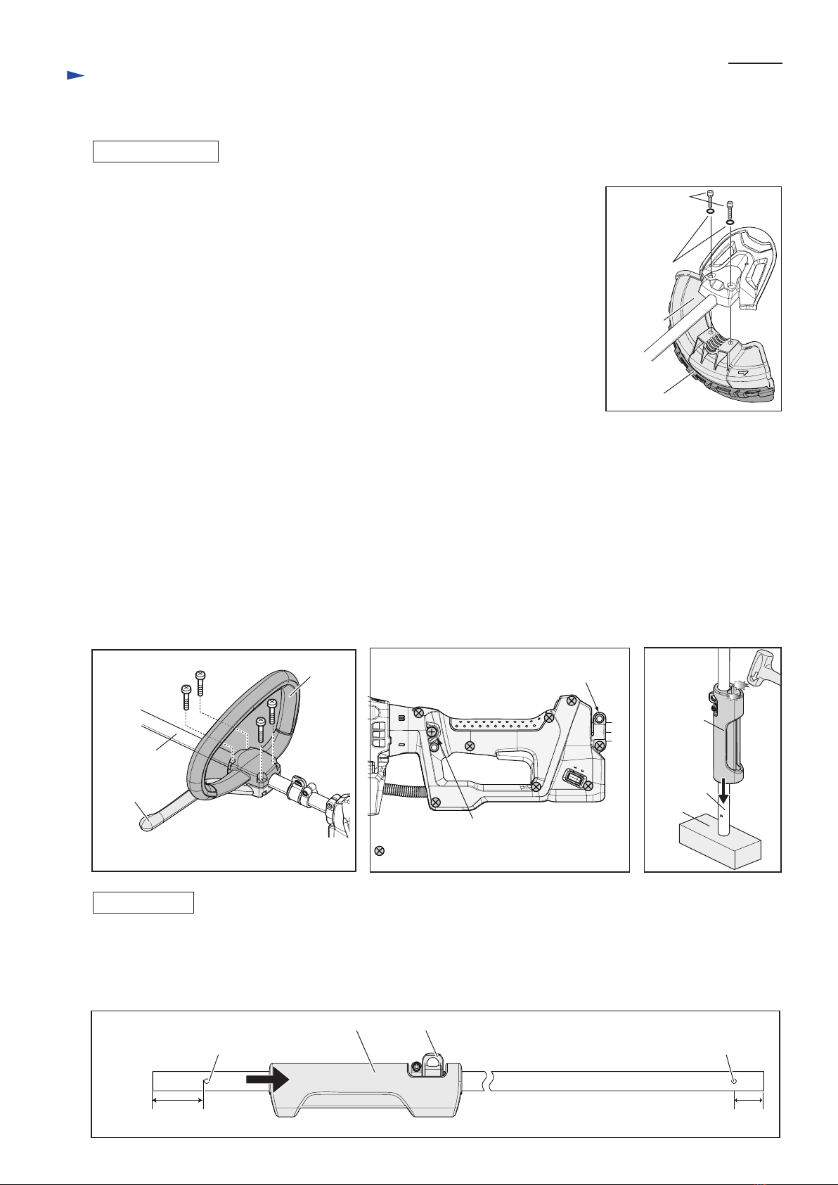
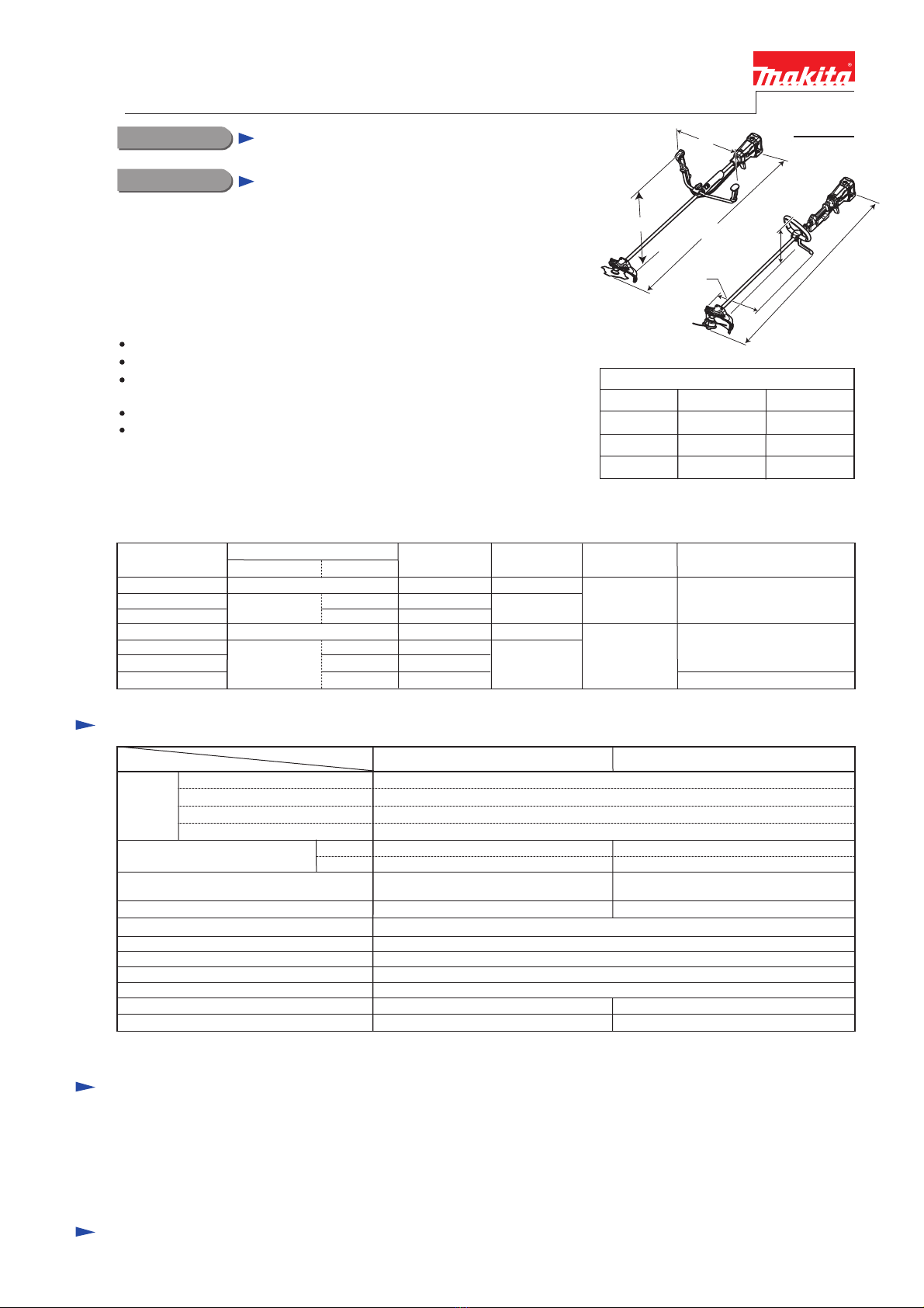
620 (24-3/8) 340 (13-3/8)
Dimensions: mm (")
Width (W)
Height (H)
Length (L)
490 (19-1/4) 325 (12-3/4)
BBC231U BBC300L
BBC231U
BBC300L
Standard equipment
Note: The standard equipment for the tool shown above may vary by country.
4-tooth star blade 230mm (9") ............................... 1 (for BBC231U)
Blade cover ............................................................ 1 (for BBC231U)
Nylon cutting head (Bump & Feed 4) ................... 1 (for BBC300L)
Shoulder harness with double shoulder straps ....... 1 (for BBC231U)
Shoulder harness with single shoulder strap .......... 1 (for BBC300L)
Universal guard (=Protector) ..................... 1
Socket wrench ............................................ 1
Hex wrench (for M4) ................................. 1
Hex wrench (for M5) ................................. 1
Models No.
Description
CONCEPT AND MAIN APPLICATIONS
BBC231U
BBC300L
Cordless Brushcutter 230mm (9")
Cordless String Trimmer 300mm (11-3/4")
Models BBC231U/ BBC300L are cordless brushcutters/ String trimmer
powered by 36V/2.6Ah Li-ion battery BL3626. As shown below, their
main advantages are "Human- and Environment-friendly" and
"Cost-effective" obtained by using Li-ion battery and Brushless DC motor
as the power unit instead of gasoline and engine:
Zero exhaust emission
Extremely low noise and low vibration
Extra-easy to start operation, simply by loading battery
then pulling switch trigger
Very low running cost owing to no fuel and oil consumption
Almost zero maintenance; no need for oil replacement,
draining fuel for storage, cleaning of air filter/muffler/spark plug,
brush replacement, etc.
With these Makita advantages, the two products will be one of the best
choices for use especially in public places or among residential areas.
Models BBC231U and BBC300L are available in the following variations.
TECHNICAL INFORMATION
1,880 (74) 1,850 (73)
L
H
W
W
L
H
Specification
94
36
Standard cutting tool
Battery
Voltage: V
Li-ion
Specifications Model
Cell
Electric brake Yes
Handle style
Overload protection Current limiter
Net weight*2: kg (lbs)
*1 No load speed of the cutting tool
*2 Weight according to EPTA-Procedure 01/2003, with Cutting tool and Shoulder harness
Nylon cutting head
BBC300L
Loop handle
5.9 (13.0)
No
230mm (9") diameter
BBC231U
Bike handle
7.1 (15.7)
No load speed*1: min.-1 = rpm
YesWaist cushion
22 with DC36RA
Charging time (approx.): min.
Energy capacity: Wh
High
Low
0 - 7,300
0 - 5,300
0 - 6,600
0 - 4,900
4-tooth star blade
Model No. Offered to
type quantity Charger
Battery Battery
cover
BBC231UZ
BBC231URD
BBC231URDE
BBC300LZ
BBC300LRD
BBC300LRDE
BBC300L
No
1
BL3626
BL3626
No
2
1
1
2
No
No
0
0
0
1
1
DC36RA
DC36RA
No
No
all countries
all countries except the
two listed below
USA, Canada
Handle
style
Bike handle
Loop handle
Pole saw attachment (for BBC300L), Cultivator attachment (for BBC300L)
The models also includes the accessories listed below in "Standard equipment".
Variable speed control Yes
Soft start Yes
Reversing switch Yes

P 2/ 12
Repair
[1] NECESSARY REPAIRING TOOLS
[2] LUBRICATIONS
Fig. 1
Code No.
1R028 Bearing setting pipe 20-12.2
1R031 Bearing setting pipe 28-20.2
1R036 Bearing setting plate 17.2
1R033 Bearing setting plate 10.2
1R045 Bearing extractor (large)
1R232 Pipe 30
1R282 Round bar for arbor 8-50
1R285 Round bar for arbor 11-50
1R291 Retaining ring S and R pliers
1R350 Ring 60
1R006 Retaining ring pliers RT-2E Removing /Assembling Retaining ring R-24
Removing /Assembling Retaining rings
Assembling Motor housing R to Motor housing L
264025-0 M10-17 Hex nut of BBC230U and AT-2623 Disassembling Cutter shaft from Gear case
Pressfitting Cutter shaft into Gear case
Removing Cutter shaft from Gear case
Removing Spindle hub from Helical gear 33 section
Removing Helical gear 33 from Spindle hub
Removing Ball bearing 6001LLU from Gear shaft
Removing Spiral bevel gear 14 (a component of Cutter shaft set)
Description Use for
Item No.
Apply the following lubricants to the portions to protect the parts and product from unusual abrasion.
Description Portion to lubricate Lubricant Amount
a little
46
Shaft
Helical gear 33
O ring 22
Spline portions
Whole portion
Gear teeth in Gear box
Rotor
Makita grease N No.2
46 Cutter shaft set Gear teeth in Gear case assembly 8g
3g
a little
CAUTION: Repair the machine in accordance with “Instruction manual” or “Safety instructions”.
35
35
Shaft pipe
88
87
71
71
87
88
Gear case assembly
Gear box
Pipe bracket cover for
BBC230U and AT-2623
Gear box cover for
BBC300L and AT-3630
Power supply cord unit for
BBC230U and AT-2623
Power supply cord unit for BBC300L and AT-3630
Tube (Refer to Fig. D-2A in Wiring diagram.)

P 3/ 12
Repair
[3] DISASSEMBLY/ ASSEMBLY
[3]-1. Shaft pipe complete (for BBC231U and AT-3623)
Fig. 2
Fig. 4Fig. 3 Fig. 5
Fig. 7Fig. 6 Fig. 8
Fig. 10 Fig. 11Fig. 9
M6x30 Hex
socket head
bolt (2pcs.)
O ring 11
(2pcs.)
Protector
Protector
clamp
Shaft pipeM5x25 Hex socket
head bolt
M5x25 Hex socket
head bolt (2pcs.)
1) Loosen two M6x30 Hex socket head bolts, and then remove Protector. (Fig. 2)
2) Enlarge the clamp pitch of Protector cover carefully and slide two holes of Protector cover from the bolts-heads of two
M5x14 Hex socket head bolts. (Fig. 3) Protector cover can be removed.
3) Remove two M5x14 Hex socket head bolts and separate Protector clamp from Gear case assembly.
Then loosen M5x25 Hex socket head bolt as the clamp of Gear case assembly. (Fig. 4)
Gear case assembly can be pulled out from Shaft pipe.
4) Remove two M5x25 Hex socket head bolts and Pipe clamp as the clamps for Handle 19.
Handle 19 section can be separated from Shaft pipe. (Fig. 5)
5) Remove M5x20 Pan head screw and M5x20 Hex socket head bolt. And then separate
Pipe bracket cover from Pipe bracket by sliding Pipe bracket cover itself in the direction
designated as illustrated in Fig. 6
6) Pull out Shaft pipe and Shaft from Pipe bracket by hand. Refer to Fig. 7.
Note: When removing Shaft is difficult, pull out Shaft with water pump pliers. (Fig. 8)
7) Remove four M4x12 screws and Battery guard. (Fig. 9)
8) Remove two 5x25 Tapping screws that fastens Gear box and Housing R, and remove
five 4x18 Tapping screws. (Fig. 10) Housing R can be removed.
9) Disconnect Power supply cord unit and Controller complete by removing their
connectors.
Then remove 4x18 Tapping screw and Strain relief from Housing L. (Fig. 11)
DISASSEMBLING
Clamp pitch of
Protector cover
Hole of Protector cover
for M5x14 Hex socket
head bolt-head
Bolt-head of M5x14
Hex socket head bolt
(2pcs.)
Gear case
assembly
M5x14 Hex socket head bolt (2pcs.)
Pipe clamp
Pipe
bracket cover
To
Cushion
side
Pipe bracket
cover
Pipe rubber
Handle 19
M5x20 Pan head screw
Battery guard 4x18 Tapping screw (5pcs.) Strain relief for
Power supply cord unit
Housing R
5x25 Tapping
screw (2pcs.)
4x18 Tapping screw
Connector of Controller
M4x12 screw (4pcs.)
M5x20 Hex
socket head screw
Pipe bracket Shaft
Shaft Shaft pipe
Shaft pipe
Cushion
Water pump pliers
Connector of
Power supply
cord unit
Power
supply
cord unit

P 4/ 12
Repair
[3] DISASSEMBLY/ ASSEMBLY
[3]-1A. Shaft pipe complete (for BBC300L and AT-3630)
Fig. 2A
O ring 11
(2pcs.)
1) Loosen two M6x30 Hex socket head bolts, and then remove Protector and
Protector extension complete. (Fig. 2A)
2) Enlarge the clamp pitch of Protector cover carefully and slide two holes of
Protector cover from the bolts-heads of two
M5x14 Hex socket head bolts. (Fig. 3) Protector cover can be removed.
3) Remove two M5x14 Hex socket head bolts and separate Protector clamp from
Gear case assembly.
Then loosen M5x25 Hex socket head bolt as the clamp of Gear case assembly. (Fig. 4)
Gear case assembly can be pulled out from Shaft pipe.
4) Remove four M6x30 Pan head screws. Loop handle 24 and Handle clamp 24 can be
removed. (Fig. 5A)
5) Remove M5x20 Pan head screw. M5x18 Hex socket head screw with washer & spring
washer, and eight 4x18 Tapping screws. Grip L and Grip R can be removed. (Fig. 5B)
6) Remove M5x20 Pan head screw and M5x20 Hex socket head bolt. And then separate
Pipe bracket cover from Pipe bracket by sliding Pipe bracket cover itself
in the direction designated as illustrated in Fig. 6
7) Pull out Shaft pipe and Shaft from Pipe bracket by hand.
Refer to Fig. 7.
Note: When removing Shaft is difficult, pull out Shaft with water pump pliers. (Fig. 8)
8) Remove four M4x12 screws and Battery guard. (Fig. 9)
9) Remove two 5x25 Tapping screws that fastens Gear box and Housing R, and remove five 4x18 Tapping screws. (Fig. 10)
Housing R can be removed.
10) Disconnect Power supply cord unit and Controller complete by removing their connectors.
Then remove 4x18 Tapping screw and Strain relief from Housing L. (Fig. 11)
11) Remove Pipe rubber, Pipe bracket cover and Shaft from Shaft pipe.
Note: Receive the end of Shaft pipe on wood and tap Cushion with plastic hammer to remove Cushion from Shaft pipe
without difficulty. Refer to Fig. 12.
DISASSEMBLING
Fig. 5A Fig. 5B Fig. 12
M6x30 Hex
socket head
bolt (2pcs.)
Protector
Protector
extension complete
M5x30 Pan head
screw (4pcs.) Loop
handle
24
Handle
clamp 24
M5x20 Pan head screw
4x18 Tapping screw (8pcs.)
M5x18 Hex socket head screw
with washer & spring washer
Shaft pipe
Fig. 13
Take the disassembling step in reverse.
Note: Shaft pipe have two holes around the both ends. Install Hanger and Cushion to Shaft pipe from the specific side
that the distance between the hole and the end is long. (Fig. 13)
ASSEMBLING
long
Hole of Shaft pipe Hole of Shaft pipe
short
HangerCushion
For all models
Wood
Shaft pipe
Cushion

P 5/ 12
Repair
Fig. 14 Fig. 16 Fig. 17
Fig. 15
Inside view
Assembled part
*Spiral bevel gear 14
*Ball bearing 609ZZ
*Retaining ring S-9
1) Remove Gear case assembly from Shaft pipe. Refer to the previous page.
2) Remove M8x10 Hex bolt with plain washer 8. (Fig. 14)
Note: Do not miss them. The installation hole on Gear case assembly is a pouring spout of lubricant to gear teeth.
If they are not seated on, Gear case assembly leaks lubricant.
3) Remove Retaining ring R-24 using 1R006. (Fig. 14)
4) Strike Gear case assembly against worktable. Spiral bevel gear 14 with Ball bearing 609ZZ and Retaining ring S-9
can be removed. (Fig. 15)
5) Remove Retaining ring S-9 using 1R291.
6) Separate Ball bearing 609ZZ from Spiral bevel gear 14 using arbor press, 1R282 and 1R031 as illustrated in Fig. 16.
The parts mentioned above are as shown in Fig. 17.
[3]-2. Gear case assembly (for all models)
M8x10 Hex bolt with
plain washer 8 Retaining
ring R-24 Arbor press
1R282
1R031
Ball bearing
609ZZ Ball bearing
609ZZ
Spiral bevel
gear 14
Spiral bevel
gear 14
M8x10 Hex bolt with
plain washer 8
Retaining ring S-9
Retaining ring R-24
Fig. 18
Fig. 19 Fig. 20
7) Remove Retaining ring R-28 using 1R291. (Fig. 18)
8) Assemble 1R033 and Receive washer to Cutter shaft by tightening M10-17 Hex nut,
and then tap Gear case assembly using plastic hammer as illustrated in Fig. 19.
Cutter shaft with Ball bearing 6001LLU can be removed by the weight of 1R033.
The parts mentioned above are shown in Fig. 20.
Note: 1) The following parts are not included in models BBC300L and AT-3630.
Therefore, they are not shown in Fig. 20. However, use M10-17 Hex nut and
1R033 to remove Cutter shaft for BBC300L and AT-3630.
*Clamp washer *Cup *M10-17 Hex nut
2) Refer to the instruction manual and the parts breakdown, and set Receive
washer in place when assembling.
9) Remove Ball bearing 6001LLU from Cutter shaft using 1R045.
1R033
M10-17 Hex nut
Plastic hammer
Receive washer
Retaining
ring R-28
Retaining
ring R-28
Ball bearing 6001LLU
Cutter shaft

P 6/ 12
Repair
[3] DISASSEMBLY/ ASSEMBLY
[3]-2. Gear case assembly (for all models) (cont.)
Fig. 21
Take the disassembling step in reverse.
Note: Pressfit Cutter shaft with Ball bearing 6001LLU into
Gear case as follows;
1) Receive Gear case on table of Arbor press so that
the shaft installation side faces the U groove of the table.
2) Press down the top of Cutter shaft using 1R028.
ASSEMBLING
Table of
Arbor press
Cutter shaft with
Ball bearing 6001LLU
1R028
U groove of table of Arbor press
Ram of Arbor press
Gear case
[3]-3. Helical gear 33, Spindle hub (for all models)
Fig. 24
Fig. 22 Fig. 23
1) Remove Gear case assembly from Shaft pipe.
2) Remove four M5x20 Pan head screws and Pipe bracket. (Fig. 22)
3) Remove Helical gear 33 with Spindle hub etc. from Gear box.
Refer to Fig. 23. The assembled section shown in Fig. 23 can be
removed as illustrated in Fig. 24.
DISASSEMBLING
M5x20 Pan head
screw (4pcs.)
Pipe bracket
Helical gear 33
Helical
gear 33
Ball bearing
6001ZZ
Ball bearing
6001ZZ
O-ring 6
Spindle hub
Spindle hub
Spindle
hub
1R036
Ball bearing
6901ZZ
Ball bearing
6901ZZ
Flat washer 12
on both side of
Helical gear 33
1R232
1R285 1R285
Fig. 25
Take the disassembling step in reverse.
Note: Refer to Figs. 23 and 25 for the positions of the components
of Helical gear 33 section.
Do not fail to set O-ring 6 and two Flat washer 12 in place.
ASSEMBLING
Ball bearing
6901ZZ
Ball bearing
6001ZZFlat washer 12
To bearing box To pipe shaft
O-ring 6
Spindle hub
Helical gear 33

P 7/ 12
Repair
[3] DISASSEMBLY/ ASSEMBLY
[3]-4. Rotor, Stator (for all models)
Fig. 26
1) Remove M5x20 Pan head screw and M5x20 Hex socket head screw,
and then slide Pipe bracket cover to Cushion side. (Fig. 6)
2) Remove four M5x20 Pan head screws and Pipe bracket. (Fig. 22)
3) Remove two M5x20 Pan head screws and Stand. (Fig. 26)
4) Remove four M5x25 Tapping screws for fastening Gear box and Housing
set. (Fig. 27) Gear box can be removed.
5) Remove four 4x18 Tapping screws and Housing R. (Fig. 28)
6) Disconnect Stator and Controller by their Connectors. (Fig. 11)
7) Remove the following parts together from Housing L.
* Gear box
* Motor housing set
* Rotor
* Stator
8) Remove four 4x18 Tapping screws and Gear box from the above parts. (Fig. 29)
9) Remove Three 4x18 Tapping screws and Motor housing R from Motor housing L.
(Fig. 30)
10) Push the shaft end of Rotor against work table and slide Stator to work table.
Then pull out Rotor from Stator. as illustrated in Fig. 31.
DISASSEMBLING
Stand
Fig. 30 Fig. 31
Fig. 27
Fig. 29Fig. 28
M5x20 Pan
head screw
(2pcs.)
5x25 Tapping
screw (4pcs.)
4x18 Tapping
screw (5pcs.) 4x18 Tapping
screw (4pcs.)
Gear box
Gear box
Housing R Motor
housing set
Motor housing R
4x18 Tapping screw (3pcs.)
Motor section consists of the above parts.
Motor housing L
Rotor
Rotor
Helical gear 16
(a component
of Rotor)
Stator
Stator
Rotor
Motor section

P 8/ 12
Repair
[3] DISASSEMBLY/ ASSEMBLY
[3]-4. Rotor, Stator (for all models)
[3]-5. Replacing Indicator (for all models)
[3]-5. Replacing Link plate (only for BBC231U and AT-3623)
Insert Rotor into Stator slowly so as not to scratch the inside of Stator.
Note: 1. Hold them firmly and carefully so that the ball bearing of Rotor does not touch
the circuit board of Stator. Quick insertion without care may cause a damage.
2. Maintain enough distance between Rotors in stock. Even if one is close to another
during carrying and storing, they suddenly attract due to strongly magnetic force.
The contact of Rotors cause cracks and damage of the magnet and weakening
the magnetic force. (Fig. 32)
3. Two halves of Motor housing set are difficult to meet their
matching surfaces.
Therefore, put them on 1R350 to align the four holes
surfaces with Gear box contact portions. And tighten three
4x18 Tapping screws for assembling Motor housing R to
Motor housing L.
Refer to Fig. 34 (for BBC231U and AT-3623) / Fig. 34A (for BBC300L and AT-3630).
Note: 1. Steel ball 5.0 and Compression spring 2 are easy to miss. Therefore, hold them by fingers and remove Indicator
from Main grip L when disassembling.
2. Insert Indicator into Main grip L, and attach Steel ball 5.0 to Indicator.
After above steps, set Compression spring 2 in place.
Fit the protrusions of Link plate into the holders of Grip L.
Fit the protrusion of Switch into the notch of Link plate.
Fit the protrusion of Lock off button into the notch of Link plate. (Fig. 35)
ASSEMBLING
Fig. 32
Fig. 33
Fig. 34
Fig. 35
Fig. 34A
Four holes surfaces of
Motor housing set for
setting Gear box in place
1R350
4x18 Tapping
screw
(3pcs.)
Indicator
Grip L
Grip L
Indicator
Steel ball 5.0
Compression
spring 2
Steel ball 5.0
Holders of Grip L
for Link plate
Notch of Link
plate for Switch Protrusion of
Switch for
Link plate
Compression
spring 2
Link plate
protrusions
Protrusion of
Lock off button
Notch of Link plate for Lock off button

Fig. D-1
Reverse switch Main switch
6-pin Connector
6-pin Connector
5-pin Connector3-pin Connector
Controller
Stator
Terminal
Circuit diagram (for all models)
P 9/ 12
Color index of lead wires' sheath
Black
White
Red
Orange
Blue
Yellow
Brown

Route Stater lead wires between Controller
and emboss of Housing L
Connect Flag terminals with Terminal so that
Lead wires face outside of Terminal. Do not
route the Lead wires between Terminal and Rib B.
Terminal viewed from the upper side
Fit 3-pin connector into the room on
Housing L as illustrated below, and then
put 6-pin connector on 3-pin connector
as illustrated right.
Before setting Main switch in place,
fit Reverse switch with lead wires into
the room and the lead wire holders of
Main grip L so that the thin lead wires
(black) should be placed lower than
the other lead wires. Be careful to
the direction of Reverse switch.
Controller Terminal of
Stator
Rib B of
Housing L
emboss of
Housing L
Fig. D-2
Wiring diagram (for BBC230U and AT-3623)
P 10/ 12
Flag terminal
Lead wires
3-pin connector
6-pin connector
5-pin
connector
Room on Housing L
for 3-pin connector
Do not put Lead wires on 3-pin connector and 6-pin connector.
Power supply cord unit
Main grip L
Tube
Rib C
Fit Connector into the room
of Main grip L as illustrated.
Be careful to the direction of
the connector.
Power supply cord unit
TubeStrain
relief
Rib A
Align one end of Power supply cord with Rib A, and
secure Power supply cord unit with Strain relief.
Do not pinch Tube between Strain relief and Housing L.
Align the other end of Power supply cord with Rib C,
and secure Power supply cord unit with Strain relief.
Do not pinch Tube between Strain relief and Main grip L.
Room on Housing L
for 5-pin connector
Terminal
Reverse switch
Reverse switch
Main switch
Flag receptacle
Flag receptacle
with sleeve
Lead wire holders
of Main grip L
thin lead
wires (black)
Room of Main
grip L for
Reverse switch

Route Stater lead wires between Controller
and emboss of Housing L
Connect Flag terminals with Terminal so that
Lead wires face outside of Terminal. Do not
route the Lead wires between Terminal and Rib B.
Terminal viewed from the upper side
Fit 3-pin connector into the room on
Housing L as illustrated below, and then
put 6-pin connector on 3-pin connector
as illustrated right.
Controller Terminal of
Stator
Rib B of
Housing L
emboss of
Housing L
Fig. D-2A
Wiring diagram (for BBC300L and AT-3630)
P 11/ 12
Flag terminal
Lead wires
3-pin connector
6-pin connector
5-pin
connector
Room on Housing L
for 3-pin connector
Do not put Lead wires on 3-pin connector and 6-pin connector.
Power supply cord unitTubeStrain
relief
Rib A
Align one end of Power supply cord with Rib A, and
secure Power supply cord unit with Strain relief.
Do not pinch Tube between Strain relief and Housing L.
Room on Housing L
for 5-pin connector
Terminal
Face the tube side of Power supply cord unit to Strain relief side, and fix Power supply cord unit with Strain relief.
(No tube on Powr supply cord unit )
(Tube side of Powr supply
cord unit with tube)
Flag receptacle Reverse switch
Flag receptacle with sleeve
Grip L
Insert Connector into
the room of Grip L as
illustrated left.
Be careful to the
direction.
Slacks in Lead wires have to
stored in the rooms designated
in arrows and circles.

Troubleshooting (for all models)
P 12/ 12
Refer to the following list.
If malfunctions are mot improved after trying the steps shown in the sheet, replace Controller.
Malfunction
Motor does not revolve.
Motor does not revolve
continuously.
Motor does not revolve
in reverse direction.
Motor does not revolve
in forward direction.
Check the connection of connectors.
Replace Reverse switch.
Warning lamps status
Neither Battery warning lamp nor
Motor warning lamp is turned on.
Battery warning lamp and Motor
warning lamp blinks alternatively.
Motor warning lamp is turned on.
Battery warning lamp is turned on.
Install Battery firmly.
Action
Check the connection of connectors.
Check if Reverse switch is shifted to reverse position.
Replace Main switch.
Recharge Battery.
Check the connection of connectors.
Replace Stator.
Check the connection of connectors.
Replace Stator.
Replace Reverse switch.
Replace Main switch.
Check the connection of connectors.
Machine reaches high temperature. Cool it down.
Motor warning lamp blinks.
Remove objects around Blade to eliminate the locking.
Check assembling Lock-off lever properly.
Check assembling the inner components of right handle.
Motor speed is not stable.
Check assembling the inner components of right handle.
Motor speed does not
reach the maximum.
Other manuals for BBC231U
10
This manual suits for next models
7
Table of contents
Other Makita Trimmer manuals

Makita
Makita UR100D User manual

Makita
Makita DUR189Z User manual

Makita
Makita GRU01 User manual

Makita
Makita HTB7600 User manual

Makita
Makita EM2600U Instruction Manual

Makita
Makita RT0700C User manual

Makita
Makita XNU05 User manual

Makita
Makita UR100D User manual

Makita
Makita UR100DSAE User manual

Makita
Makita UH6570 Manual

Makita
Makita UR006G User manual

Makita
Makita BUR141 User manual

Makita
Makita XRU11 User manual

Makita
Makita DUR141 User manual

Makita
Makita DUR368A User manual

Makita
Makita UH5570 User manual

Makita
Makita EM3400U User guide

Makita
Makita DUX60 User manual

Makita
Makita BC231UD User manual

Makita
Makita GRU02 User manual