Malmet WDS Series User manual

Serial Number:
Supplied to:
Date Installed:
Installed by:
Issue 11
Head Office and Customer Service
ABN 95 001 717 791
9-11 McKay Avenue
PO Box 373
Leeton NSW 2705
Phone: +61 2 6953 7677
Bedpan/Urinal Bottle and Utensil/Bowl
Washer Disinfector
Models WDS1; WDS3
Operation, Maintenance and
Installation Manual
Note: Due to Malmet’s Policy of continuous product improvement;
design and technical specifications are subject to change without notice.

WDS
Operation, Maintenance and Installation Manual
Issue 11 Page 1 14/02/2019
Table of Contents
Foreword...........................................................................................................................................................................2
Certifications and Compliances.........................................................................................................................................2
Quality Policy ....................................................................................................................................................................2
Safety Instructions ............................................................................................................................................................3
1.0 Design Parameters ................................................................................................................................................4
1.1 Operating Cycles ........................................................................................................................................4
1. 2 Detergent ...................................................................................................................................................5
1.3 Device Features ..........................................................................................................................................6
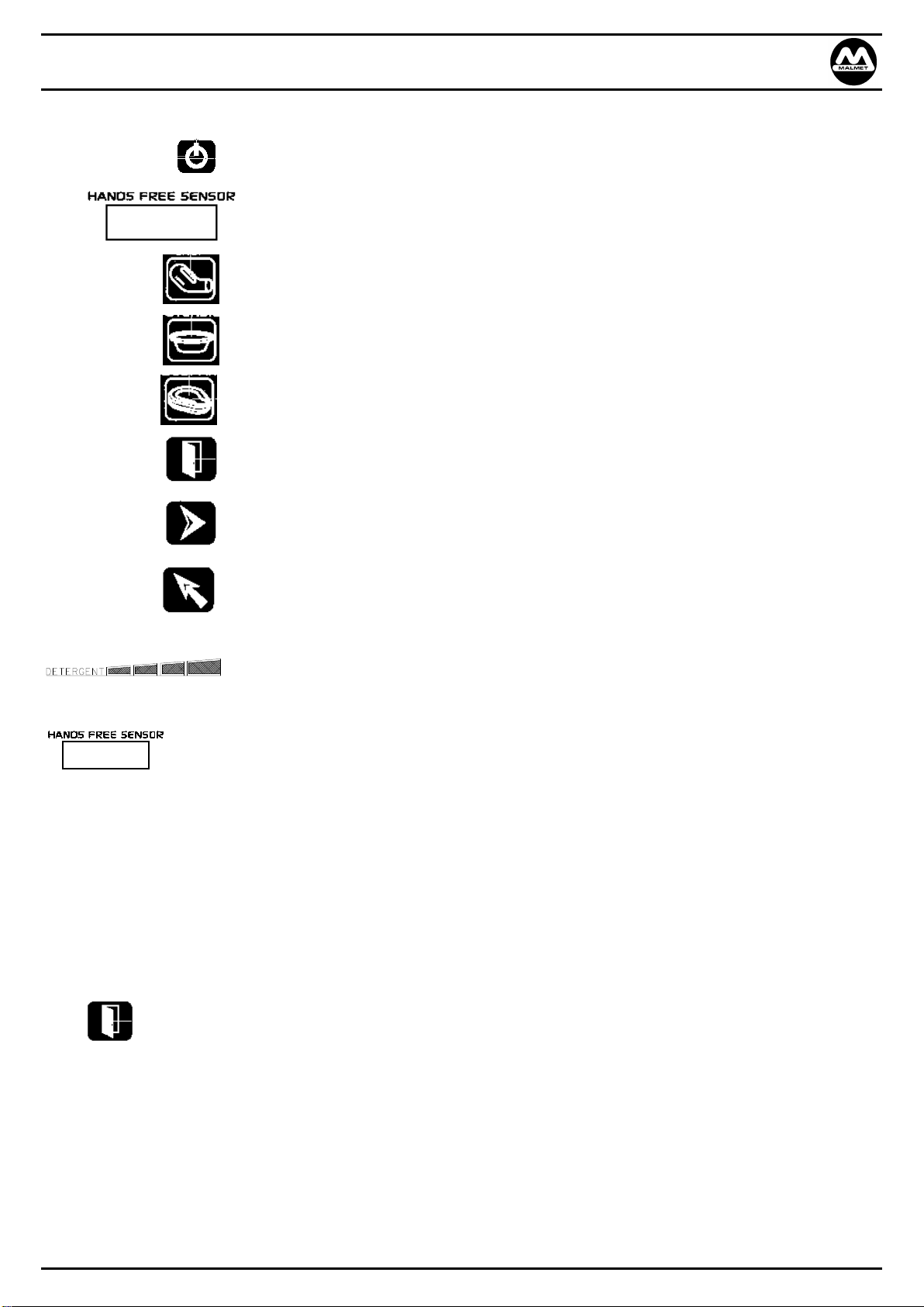
1.4 Control LCD Display Features .....................................................................................................................6
1.5 Operating Features ....................................................................................................................................6
2.0 Installation and Commissioning ............................................................................................................................8
2.1 Installation .................................................................................................................................................8
2.2 Service Connection and Layout Details ....................................................................................................10
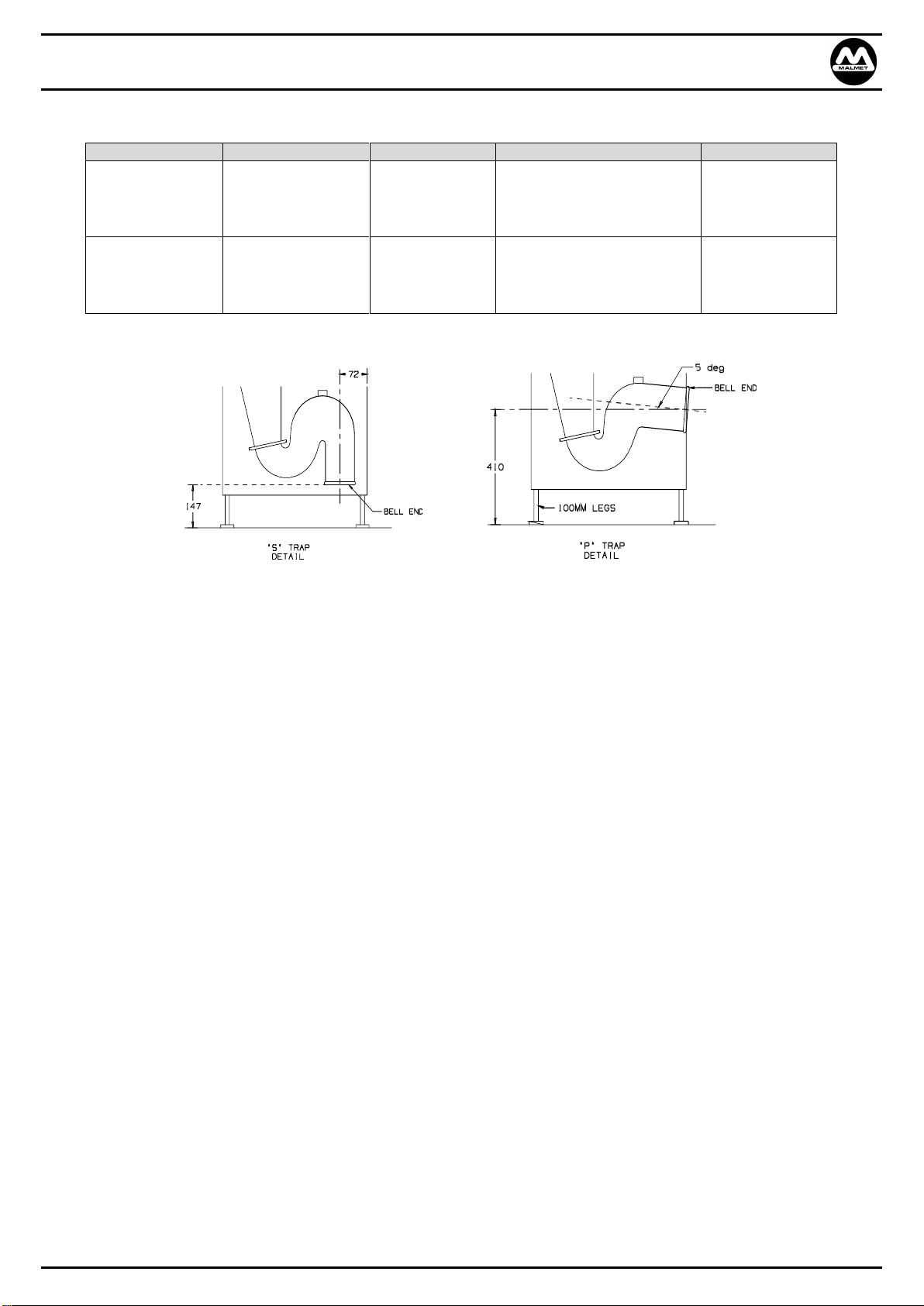
2.3 Plumbing ..................................................................................................................................................11
2.4 Electrical...................................................................................................................................................12
2.5 Commissioning .........................................................................................................................................12
3.0 Loading and Operating .............................................................................................................................................13
3.1 Urinal Bottle / Bedpan - Loading..............................................................................................................13
3.2 Urinal Bottle / Bedpan - Operating Cycle.................................................................................................13
3.3 Urinal Bottle ONLY - Loading....................................................................................................................15
3.4 Urinal Bottle ONLY - Operating Cycle.......................................................................................................15
3.5 Bowl / Utensil - Loading ...........................................................................................................................17
3.6 Bowl / Utensil - Operating Cycle ..............................................................................................................17
4.0 Cycle of Operation.....................................................................................................................................................19
4.2 Detergent Warnings.................................................................................................................................24
4.3 Fault Indication ........................................................................................................................................24
5.0 Maintenance .............................................................................................................................................................25
5.1 Daily Maintenance (Operator or Maintenance Technician) ....................................................................25
5.2 Bi-Monthly Maintenance (Maintenance Technician)...............................................................................25
5.3 Recommended Preventative Maintenance Schedule...............................................................................26
5.4 Fault Codes...............................................................................................................................................27
5.5 Purge Reset (Operator) ............................................................................................................................30
5.6 Purge Detergent Line (Operator) .............................................................................................................30
5.7 Purge Reset (Maintenance)......................................................................................................................31
5.8 Purge Detergent Line (Maintenance).......................................................................................................31
5.9 Detergent Level and Load Cell Calibration...............................................................................................32
5.10 Device Service Component Identification and Part Listing.......................................................................33
5.11 User Menu and Test Mode.......................................................................................................................36
6.0 Technical Data ..........................................................................................................................................................39
6.1 Power and Water Consumption...............................................................................................................39
6.2 Device Specifications................................................................................................................................40
6.3 Wiring Diagram (1ph devices)..................................................................................................................42
6.4 Wiring Diagram (3ph devices)..................................................................................................................43
6.5 Data Logging............................................................................................................................................44
Warranty Statement .......................................................................................................................................................50

WDS
Operation, Maintenance and Installation Manual
Issue 11 Page 2 14/02/2019
Foreword
In order to obtain maximum life and efficiency from your Malmet Bedpan/Urinal Bottle and Utensil/Bowl Washer Disinfector and to
aid in the safe operation of the device, please read and understand this manual thoroughly and follow all instructions before
operating the device.
This device is not intended for use by persons (including children) with reduced physical, sensory or mental capabilities, or lack of
experience and knowledge.
Children should be supervised to ensure that they do not play with the device.
The specifications supplied in this manual were in effect at time of publication, however due to Malmet (Australia)’s policy of
continuous improvement, changes to these specifications may be made at any time without notice on the part of Malmet (Australia)
Pty Ltd.
Certifications and Compliances
ARTG Identifier: 232450
Electrical Safety Cert: CS10462N
Watermark Cert: WMKA21156
Quality Policy
Malmet (Australia) Pty Ltd is Quality Certified to ISO 13485; ISO 9001; AS 3902; NZS 9002 and guarantees the quality of this device.
Should you have any problems with your device, contact the company from whom you purchased it, or Malmet (Australia) Pty Ltd.
Malmet (Australia) Pty Ltd
Head Office and Factory
9-11 McKay Ave
PO Box 373
LEETON NSW 2705
Telephone: +61 2 6953 7677
Website: www.malmet.com.au

WDS
Operation, Maintenance and Installation Manual
Issue 11 Page 3 14/02/2019
Safety Instructions
WARNINGS
Be aware of 240V / 415V Voltage
Disconnect power when servicing
Mains power ISO switch must be in an accessible position so device can be
isolated from mains power during service
Be aware of steam discharge
Utensils and racks are hot to handle
Safety gloves and goggles must be worn when changing detergent
Safety clothing with reflective tape can activate the hands free sensor when
device is in standby mode
Be aware of hot pipes and hoses from steam and hot water
Install temperature probes and element over temperature thermal cut-outs
correctly
Not suitable for use in the presence of a flammable anaesthetic mixture with
air or nitrous oxide and mode of operation as continuous

WDS
Operation, Maintenance and Installation Manual
Issue 11 Page 4 14/02/2019
1.0 Design Parameters
The Malmet Bedpan/Urinal Bottle and Utensil/Bowl Washer Disinfector has been designed within the following parameters:
1.1 Operating Cycles
Three available operating (cleaning and disinfection)
Urinal Bottle / Bedpan
Load: capacity: 2 x small slipper pans, 2 x large slipper pans, 2 x standard bedpans and 4 x standard male and
female urinal bottles
Cycle:
1. Flush 8 to 12 sec
2. Cold water wash 2 min
3. Hot water wash with detergent 2 min
4. Hot water rinse 35 sec
5. Disinfection 1 min at 90˚C
6. Cool down 20 sec
Urinal Bottle only
Load capacity: 4 x Standard male and female urinal bottles
Cycle:
1. Cold water 2 min
2. Hot water wash with detergent 2 min
3. Hot water 35 sec
4. Disinfection 1 min at 90˚C
5. Cool down 20 sec
Bowl / Utensil
Load capacity: 2 x large bowls (345Dia to 305Dia), 3 x medium bowls (240Dia to 210Dia), 6 kidney dishes (sizes
300 x 50, 255 x 50 and 220 x 43 –held in kidney rack holder)
Smaller kidney dishes fit into a basket with a smaller open ended trays and utensils.
Cycle:
1. Cold water wash 2 min
2. Hot water wash with detergent 2 min
3. Hot water rinse 35 sec
4. Disinfection 1 min at 90˚C
5. Cool down 20 sec
Note: These times do not include filling and heating. These times comply with AS 2945. See Technical data for full cycle
times.
a) Two bedpans with lids and four urinal bottles can be emptied, cleaned and disinfected during each automatic cycle.
b) The cradle is designed to ensure that utensils are not dislodged during the cleaning cycle; the contents are emptied during
door closure.
c) The chamber and door are self-cleaning and do not permit water or soil to remain after a properly completed cycle. Steam
disinfecting ensures all internal surfaces are totally clean and safe.
d) The bedpan flush cycle:
i) Removes the heavy soil
ii) Clears the trap

WDS
Operation, Maintenance and Installation Manual
Issue 11 Page 5 14/02/2019
1. 2 Detergent
The 5 litre detergent container is accessed by opening the bottom door. Only use Malmet approved detergent (See technical
data for detergent details)
1. Pull handle on detergent door and open
2. Unscrew cap and pull out with suction hose (let hose hang in detergent chamber)
3. Remove empty bottle and replace with full bottle
Note: Leave cap on new bottle until in position
4. Remove cap on new bottle and fit existing hose and cap, make sure suction hose is at bottom of bottle
5. Close detergent door
6. Restart device operation as normal
7. Check fill level indicator on display. Should show as
Note: Do not drop detergent container onto base plate. This may result in damaging the load cell.
Safety Gloves and Goggles must be worn when changing detergent. Current Safety Data Sheet for Malmet Detergent is
available in pdf format from Malmet’s website. www.malmet.com.au

WDS
Operation, Maintenance and Installation Manual
Issue 11 Page 6 14/02/2019
1.3 Device Features
1.4 Control LCD Display Features
Control panel with LCD display
Emergency cycle stop
Bowl / Utensil rack, hinged
Bedpan rack, hinged
Door Auto open and close
Detergent access door
USB port
Wash Chamber
Urinal bottle rack
LCD

WDS
Operation, Maintenance and Installation Manual
Issue 11 Page 7 14/02/2019
1.5 Operating Features
POWER On/Off Standby
HANDS FREE SENSOR For hands free opening, closing door and starting of cycle. To operate,
hold hand in front of sensor
URINAL BOTTLE ONLY Select and start for urinal bottle only cycle
BOWL / UTENSILS Select and start for bowls / kidney dishes etc
URINAL BOTTLE / BEDPAN Select and start for urinal bottles / bedpans
DOOR To manually open and close door, if pressed whilst door is closing at
the start of a cycle the cycle will be cancelled and the door opened
SCROLL Menu scroll button SERVICE ONLY
SELECT Menu select and enter button SERVICE ONLY
Purge Reset: When “purge” is flashing on display, if pressed this will
start the purge cycle after a fault.
Detergent level indicator (only visible with power on)
Hands free operation
By using the hands free option the door can be opened and closed automatically
Place hand in front of window for approx. 2 seconds, the door will open
To close the door the display will show ‘CLOSE DOOR’
Place hand in front of hands free window for approx. 2 seconds, the door will close
Once the door is closed the text “Hands Free Start” will flash for 10 seconds, place hand in front of hands free
window for approx. 2 seconds to start the selected cycle (selected by the rack position)
Manual operation of the door
Press the door button the door will open
To close the door the display will show door close
Press the door button and the door close
When the door is closed the cycle selected will start

WDS
Operation, Maintenance and Installation Manual
Issue 11 Page 8 14/02/2019
2.0 Installation and Commissioning
2.1 Installation
Before unpacking device inspect carton for any damage relating to forklift forks and damage relating to device falling over
or for evidence of top loading
Remove carton from device; inspect all external panels for damage
Warning - Device Weight
Shipping 163 kg
Nett unpacked 140 kg
2.1.1 Positioning the WDS
Freestanding Model
Model
Placement
Access Required
Device Dimensions
Height
Width
Depth (mm)
WDS1; WDS3
Freestanding
Both Sides
1685
605
625
Please allow sufficient room for servicing purposes. Recommended space requirements 300mm on either side with
150mm at the rear of the device.
Buildings
Service connections are usually pre-placed after planning and consultation with all interested parties. Installation is by
connection to the services provided
As the soil line (sewerage outlet) is the least flexible of all the connections, this usually influences the decision as to where
to place the WDS. If an existing soil line can be utilised this will represent a cost saving
The WDS is supplied with either an ‘S’ or ‘P’ Trap as nominated by the Purchaser. The ‘S’ Trap connects through the floor
and the ‘P’ Trap connects through the back wall. The trap section is easily removed if the wrong trap has been ordered.
Refer to Diagram C2 for trap connections.
Potential electromagnetic or other interference between other EQUIPMENT and other devices can possibly affect the
infra-red hands free operation sensor. It is advisable to check all the equipment and devices in the intended installation
area that have infra-red operation. Electromagnetic interference can be prevented by installing the device in non patient
areas of hospital (or similar)

WDS
Operation, Maintenance and Installation Manual
Issue 11 Page 9 14/02/2019
Service Connections
MODEL
HOT WATER
COLD WATER
SOIL LINE
ELECTRICAL
WDS1
(1ph)
Solenoid valve GB¾
Male
Solenoid valve
GB¾ Male
100mm ‘S’ or ‘P ’Trap
Hot water discharge
75-80°C
240V
1 Phase
20 Amps
50 Hertz
WDS3
(3ph)
Solenoid valve GB¾
Male
Solenoid valve
GB¾ Male
100mm ‘S’ or ‘P ’Trap
Hot water discharge
75-80°C
415V
3 Phase
20 Amps
50 Hertz
Note: Bell ends can be cut off to suit
Diagram C2
For reasonable connection working space allow 150-200mm from rear of device to wall.
The device is 600mm wide and the centre of the trap is 300mm from each side.
FREE STANDING
‘S’ TRAP PIPE POSITIONING
FREE STANDING
‘P’ TRAP PIPE POSITIONING
The centre of the soil line to receive the ‘S’ Trap
should be approximately 272mm from the back wall.
To allow for normal recommended minimum side
service access, space soil line 600/700mm from side
wall.
If space restrictions do not allow for recommended
side service access, we suggest preference be given
to providing the most space available on the right
hand side as you look at the front of the device.
This will ease any difficulty in servicing the steam
tank element and probe.
The centre of the soil line to receive the ‘P’ Trap
should be approximately 410mm from the floor
when the device is positioned 150mm from the wall.
Because this pipe is graded to 5° this measurement
will vary as the device is installed closer or further
away from the back wall.
Steam Venting
No external vent pipe work is required as the device is designed to condensate all visible steam internally.

WDS
Operation, Maintenance and Installation Manual
Issue 11 Page 10 14/02/2019
2.2 Service Connection and Layout Details

WDS
Operation, Maintenance and Installation Manual
Issue 11 Page 11 14/02/2019
2.3 Plumbing
These installation guidelines must be followed to ensure the device will operate as intended
Installations must be carried out by a qualified, licensed tradesperson
Service Connections
NOTE: Plumbing connection must comply with AS3500 and be Watermark Certified
Waste connection
HOT AND COLD WATER CONNECTIONS ARE REQUIRED. The device can be connected to any normal mains pressure hot
and cold water supply. A back flow prevention air gap is incorporated in the design of the water tank. Complies to AS
2845.2
The water supply is to be connected to an isolating valve or cistern stopcock placed approximately 1200mm from the
floor to the right-hand side of the device (preferably not behind the device)
Cold water: Flow pressure Kpa 100 min 350 max. Temperature 15° - 25° C
Hot water: Flow pressure Kpa 100 min 350 max. Temperature 55° - 60° C
Minimum water flow for 100Kpa 9.377L/min
If inlet water flow pressure is higher than 350 Kpa an inline pressure reducing valve should be fitted
Soil Line
Hot water. Discharge temp 75° –80° C. Soil line must comply to AS3500
Soil line connection is by a pan collar or other preferred method. If the belled end on the polyethylene moulded trap is
not required it can easily be cut off to provide a straight pipe connection
Level the device by using the flanged screw in legs and if possible maintain approx. 100mm floor clearance for ease of
floor cleaning. Malmet recommends affixing some of the leg flanges to the floor via stainless self-tapping screws to
prevent sideways movements and damage to services and soil line connections
The soil line should protrude from the floor or wall at a minimum of 100mm

WDS
Operation, Maintenance and Installation Manual
Issue 11 Page 12 14/02/2019
2.4 Electrical
These installation guidelines must be followed to ensure the device will operate as intended
Installations and service must be carried out by a qualified, licensed electrical tradesperson
Model: WDS 1ph 240V 50Hz 1 ph 20Amp
WDS 3ph 415V 50Hz 3 ph 20Amp
Devices are supplied with 1700mm power supply cord extending from the rear top right hand side of the device for hard
wiring into Mains ISO switch. Position switch approx. 1500mm above floor level
Mains power ISO switch must be in an accessible position so device can be isolated from mains power during service
Malmet recommends having a 30mA RCD in the mains supply fixed wiring
If the supply cord is damaged, it shall be replaced by the manufacturer or its service agent or similarly qualified person in
order to avoid any potential hazard
2.5 Commissioning
a) Before switching on the device make sure the DEVICE IS LEVEL and WATER TAPS ARE ON. Check that the DRAIN WASTE
is connected
b) Turn on the power at the isolation switch. Turn on circuit breakers inside electrical cover and press the standby button
on the front display. The LCD display will illuminate and go to standby mode
c) Check that the water tank is filling with cold water and that it has fill to Level 3. Ensure the lid is put back on water tank
d) Check that the steam generator tank has filled to the full Level 3. The steam generator will preheat to 85°C in standby
mode or during cycle
e) Check that the 5 litre detergent bottle has been fitted. From the menu, run the DETERG/START to purge detergent
through the line to flow sensor. This may need to be done twice if the line is empty on start-up (see 5.6)
f) Flush approximately 1 litre of water down the steam generator tank overflow pipe. This will fill the ‘S’ Trap at the hose
junction and prevent steam coming back up into the water tank
g) From the Menu, run Purge Reset three times (see 5.5). Check for any water leaks
h) Open the door and turn power off at the control. Check racks for freedom of movement. Check that flush nozzles rotate
freely. Check that all spray nozzles are tight. Turn power back on and close door by pressing the door button
i) Select the BEDPAN/URINE cycle and let it run through the cycle. Repeat the same procedure for the URINE and BOWL
cycles.
j) Replace all covers
Note: DO NOT USE THE DEVICE WITHOUT THE WATER SUPPLY TURNED ON

WDS
Operation, Maintenance and Installation Manual
Issue 11 Page 13 14/02/2019
3.0 Loading and Operation
3.1 Urinal Bottle / Bedpan –Loading
Refer to laminated WDS Instructions
1. To open door, use or press
2. Place racks into the correct positions
3. Place bedpan lids into back of bowl rack
4. Place first bedpan onto top rack, or large/small slipper pan
5. Place second bedpan onto bottom rack or large/ small slipper pan
6. Place urinal bottles into rack
Lift bedpan rack up and lock
into position.
Check that bowl
rack is in the up
position.

WDS
Operation, Maintenance and Installation Manual
Issue 11 Page 14 14/02/2019
3.2 Urinal Bottle / Bedpan –Operating Cycle
Refer to laminated WDS Instructions
1. Open door, use or press
2. Select URINE / BEDPAN cycle by adjusting the rack position as shown
3. Close door, use the or press
4. When the door closes, to start cycle use the or press whilst “START” is flashing for 10 sec
Alternatively the can be pressed to close the door and automatically start the cycle
Cycles will be shown on LCD display
1. Flush
2. Cold water wash
3. Hot water wash with detergent
4. Hot water rinse
5. Disinfection
6. Cool down
7. Completed
When the cycle is completed the display will show COMPLETED. OPEN DOOR
Open door, use or press
NOTE: If temperature inside the chamber is too high the display will flash, WAITING COOLING
When the temperature has dropped to a safe level the display will flash, OPEN DOOR
Open door, use or press
To run the same cycle repeat steps 1 to 3
If you don’t need to run another cycle, close door by pressing
NOTE:
When the cycle has started the operating cycle cannot be interrupted
In an emergency, if the cycle needs to be stopped press the EMERGENCY CYCLE STOP button
The display will show a Fault code 904 (see note below)
NOTE:
If a FAULT code is displayed on LCD display contact the Service Engineer to rectify

WDS
Operation, Maintenance and Installation Manual
Issue 11 Page 15 14/02/2019
3.3 Urinal Bottle Only –Loading
Refer to laminated WDS Instructions
1. Open door, use or press
2. Place racks into correct positions
3. Place urinal bottles into rack
Bedpan rack must be in
the down position
Check that the bowl
rack is in the up
position

WDS
Operation, Maintenance and Installation Manual
Issue 11 Page 16 14/02/2019
3.4 Urinal Bottle Only –Operating Cycle
Refer to laminated WDS Instructions
1. Open door, use or press
2. Select URINE / BEDPAN cycle by adjusting the rack position as shown
3. Close door, use or press
4. When the door closes, to start the cycle use or press whilst “START’ is flashing for 10 sec
Alternatively the can be pressed to close the door and automatically start the cycle
Cycles will be shown on LCD display
1. Cold water wash
2. Hot water wash with detergent
3. Hot water rinse
4. Disinfection
5. Cool down
6. Completed
When the cycle is completed the display will show COMPLETED OPEN DOOR
4. Open door, use or press
NOTE: If temperature inside the chamber is too high the display will flash, WAITING COOLING
When the temperature has dropped to a safe level the display will flash, OPEN DOOR
To open door, use or press
5. To run the same cycle repeat steps 1 to 3
6. If you don’t need to run another cycle close door by pressing
NOTE:
When the cycle has started the operating cycle cannot be interrupted
In an emergency, if the cycle needs to be stopped press the EMERGENCY CYCLE STOP button
The display will show a Fault code 904 (see note below)
NOTE:
If a FAULT code is displayed on LCD display contact the Service Engineer to rectify

WDS
Operation, Maintenance and Installation Manual
Issue 11 Page 17 14/02/2019
3.5 Bowl / Utensil - Loading
Refer to laminated WDS Instructions
1. Open door, use or press
2. Place racks into the correct positions
3. Examples of bowls and utensils placed onto racks
Large and medium size bowls
Medium size kidney dishes
Kidney dish rack placed onto bowl rack Load kidney dishes into rack
Smaller items can be placed into accessory basket
Basket placed onto bowl rack
Place bedpan rack
into the down
position
Place the bowl
rack in the down
position

WDS
Operation, Maintenance and Installation Manual
Issue 11 Page 18 14/02/2019
3.6 Bowl / Utensil –Operating Cycle
Refer to laminated WDS Instructions
1. Open door, use or press
2. Select URINE / BEDPAN cycle by adjusting the rack position as shown
3. Close door, use or press
4. When the door closes, to start the cycle use or press whilst “START’ is flashing for 10 sec
Alternatively the can be pressed to close the door and automatically start the cycle
Cold water wash
1. Hot water wash with detergent
2. Hot water rinse
3. Disinfection
4. Cool down
5. Complete
When the cycle is completed the display will show COMPLETED OPEN DOOR
5. Open door, use or press
NOTE: If temperature inside the chamber is too high the display will flash WAITING COOLING
When the temperature has dropped to a safe level the display will flash OPEN DOOR
6. To Open door, use or press
7. To run the same cycle repeat steps 1 to 3
8. If you don’t need to run another cycle close door by pressing
NOTE:
When the cycle has started the operating cycle cannot be interrupted
In an emergency, if the cycle needs to be stopped press the EMERGENCY CYCLE STOP button
The display will show a Fault code 904 (see note below)
NOTE:
If a FAULT code is displayed on LCD display contact the Service Engineer to rectify

WDS
Operation, Maintenance and Installation Manual
Issue 11 Page 19 14/02/2019
4.0 Cycle of Operation
1. Press POWER ON button; display shows:
POWER
After short delay display shows alternating
OPEN
DOOR
2. Open door; display shows:
OPENING
3. When door is open; display shows:
LOAD
ITEMS
After a short delay, display shows the rack position (Urine, Bedpan & Urine or Bowl) with
SELECT
CYCLE
If the wrong cycle has been selected for the position of the racks; display briefly shows:
WRONG
RACK
Then
SELECT
CYCLE
POWER
OPENING
LOAD-ITEMS
SELECT-CYCLE
WRONG-RACK
OPEN-DOOR
This manual suits for next models
2
Table of contents
Other Malmet Laboratory Equipment manuals
Popular Laboratory Equipment manuals by other brands

Retsch
Retsch SM100 operating manual

Sakura Seiki
Sakura Seiki Cyto-Tek 2500 operating manual

Thermo Scientific
Thermo Scientific Harris MBF-700 Installation and operation manual

Codonics
Codonics Horizon GS manual

Liquid Instruments
Liquid Instruments Moku:Go quick start guide

WPI
WPI MICRO-ePUMP instruction manual