Malmet F105BT User manual
Serial Number:
Supplied to:
Date Installed:
Installed by:
It is important that the name from whom you purchased your device and the name of the installer are recorded above. The installer is responsible for the correct
installation, start up and demonstrating the operation of this device. They are also responsible for issuing relevant certificates of compliance (these may differ from
state to state).
Issue 18 Jun-23
Head Office and Customer Service
ABN 95 001 717 791
9-11 McKay Avenue
PO Box 373
Leeton NSW 2705
Phone: +61 2 6953 7677
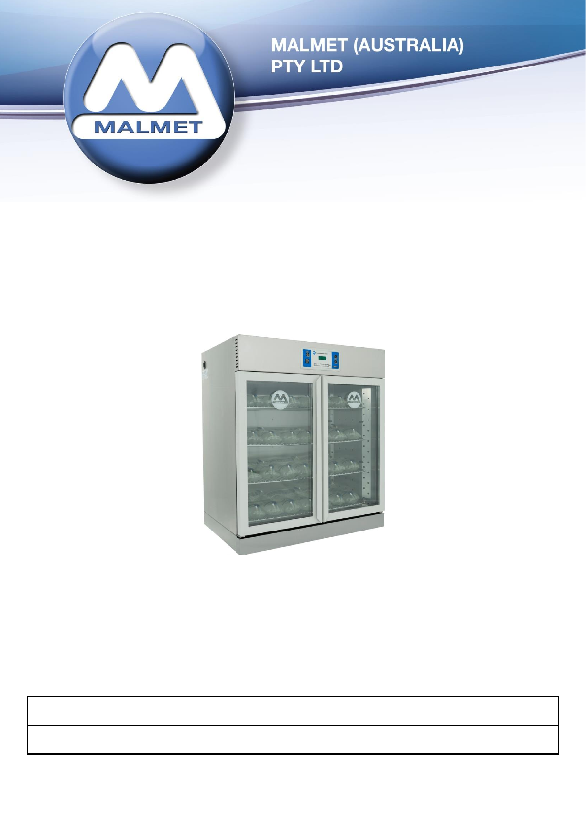
Fluid Warming Cabinet
Single Models:
F105BT; F420FS; F420C; F210FS; F210C; F210WB; F210S; F260FS; F260C; F260WB; F260S
Combination Models:
FF105FS; FB105FS; FS105FS; FF210FS; FB210FS; FS210FS; FF210C; FB210C; FS210C
FF260FS; FB260FS; FS260FS; FF260C; FB260C; FS260C
Operation, Maintenance and Installation
Manual
Note: Due to Malmet’s Policy of continuous product improvement;
design and technical specifications are subject to change without notice.

Fluid Warming Cabinet
Operation, Maintenance and Installation Manual
Issue 18 Page 1 Jun-23
Table of Contents
Foreword..........................................................................................................................................................................2
Certifications and Compliances.........................................................................................................................................2
Quality Policy....................................................................................................................................................................2
Important Warranty Reminder .........................................................................................................................................2
Malmet Head Office and Factory Contact Details .............................................................................................................2
Safety Instructions - Warnings..........................................................................................................................................3
1.0 Design Parameters......................................................................................................................................................4
1.1 Device Operation ..........................................................................................................................................................5
1.2 Control Display Features ...............................................................................................................................................5
1.3 Operating Features .......................................................................................................................................................5
1.4 Changing the set temperature (lock out feature) .........................................................................................................6
1.5 Temperature Cut Out....................................................................................................................................................6
1.6 Temperature Sensor Plate ............................................................................................................................................6
2.0 Installation..................................................................................................................................................................7
2.1 Service Connections ......................................................................................................................................................9
2.2 Device Dimension and Clearances ................................................................................................................................9
3.0 Maintenance.............................................................................................................................................................13
3.1 Preventative Maintenance..........................................................................................................................................13
3.2 Replacement of Safety Devices...................................................................................................................................13
3.3 Trouble Shooting Guide ..............................................................................................................................................14
4.0 Technical Specifications ............................................................................................................................................15
4.1 Device Specifications...................................................................................................................................................15
4.2 Wiring Diagram ...........................................................................................................................................................16
Warranty Statement.......................................................................................................................................................17

Fluid Warming Cabinet
Operation, Maintenance and Installation Manual
Issue 18 Page 2 Jun-23
Foreword
To obtain maximum life and efficiency from your Malmet Warming Cabinet and to ensure safe operation, please
read this manual thoroughly and follow all instructions before operating the device.
This manual provides information on the operation of the device. It is recommended that all persons operating the
device have access to this manual for training purposes.
This device is not intended for use by any person without the proper training, experience or knowledge.
This appliance is not intended for use by persons (including children) with reduced physical, sensory or mental
capabilities, or lack of experience and knowledge, unless they have been given supervision or instruction concerning
use of the appliance by a person responsible for their safety.
Children should be supervised to ensure that they do not play with the appliance.
The specifications supplied in this manual were in effect at the time of publication. However, owing to Malmet
(Australia)’s policy of continuous improvement, changes to these specifications may be made at any time without
notice on the part of Malmet (Australia) Pty Ltd.
Certifications and Compliances
ARTG Registration Number: 188762 Class 1
Electrical Safety: Certificate of Suitability SAA210223 to AS/NZS 60335.1:2020
EMC compliant: IEC 60601-1-2 Emission
Quality Policy
Malmet’s quality management system is certified to ISO 13485:2016 and ISO 9001:2015 and guarantees the
quality of this product.
Important Warranty Reminder
Should you have any problems with your device, contact the company from whom you purchased it, or Malmet
(Australia) Pty Ltd.
It is important that the name from whom you purchased your device and the name of the installer are recorded
on the front page of this manual. The installer is responsible for the correct installation, start up and
demonstrating the operation of this device. They are also responsible for issuing relevant certificates of
compliance (these may differ from state to state).
Malmet Head Office and Factory Contact Details
Malmet (Australia) Pty Ltd
9-11 McKay Avenue
PO Box 373
LEETON NSW 2705
Telephone: +61 2 6953 7677
Website: www.malmet.com.au

Fluid Warming Cabinet
Operation, Maintenance and Installation Manual
Issue 18 Page 3 Jun-23
Safety Instructions - Warnings
Please read and understand this manual before using this device, if this device is used in a manner not specified
by the manufacturer protection by the device may be impaired.
Please refer to this manual for information wherever this warning symbol is displayed -
Be aware of 240 Voltage.
Disconnect power when servicing.
Mains power GPO must be in an accessible position so device can be
isolated from mains power during service.
If the supply cord is damaged it must be replaced by a special cord or
assembly from the manufacturer or its service agent.
Do not overload shelves.
Do not obstruct hot air outlet above top shelf.
Castors where fitted are for convenience but not as a means to be
wheeled across thresholds or similar obstacles. Castors enable the device
to be moved easily aside for cleaning the floor or making space.
Wall mounted units must be mounted to load bearing walls.
All cabinets should be located on a level floor surface and should never be
operated on a sloping surface.
Install temperature probes and element over temperature protection
thermal cut-outs correctly.
This Warming Cabinet is not intended for use by persons (including
children) with reduced physical, sensory, or mental capabilities, or lack of
experience and knowledge.

Fluid Warming Cabinet
Operation, Maintenance and Installation Manual
Issue 18 Page 4 Jun-23
1.0 Design Parameters
Single 105 Litre Fluid Warming Cabinet (Model F105BT) is designed to hold a maximum of 24 litres of fluid in 1
and 2 litre bottles and bags. 105 litre models have 3 shelves with 2 being adjustable; 8 litres per shelf maximum
load.
Single 210 Litre Fluid Warming Cabinets (Models F210FS, F210C, F210WB, F210S) are designed to hold a
maximum of 45 litres of fluid in 1 and 2 litre bottles and bags. 210 litre models have 3 shelves with 2 being
adjustable; 15 litres per shelf maximum load.
Single 260 Litre Fluid Warming Cabinets (Models F260FS, F260C, F260WB, F260S) are designed to hold a
maximum of 60 litres of fluid in 1 and 2 litre bottles and bags. 260 litre models have 4 shelves with 3 being
adjustable; 15 litres per shelf maximum load.
Single 420 Litre Fluid Warming Cabinets (Models F420FS and F420C) are designed to hold a maximum of 105
litres of fluid in 1 and 2 litre bottles and bags. 420 litre models have 7 shelves with 6 being adjustable; 15 litres
per shelf maximum load.
Do not overload shelves. Heated air must be allowed to circulate around the fluid containers.
The temperature can be adjusted up to a maximum of 37°C and has a lock out feature, which allows only
authorised staff to change the temperature.
A fluid temperature sensor plate is located in the cabinet, which enables actual fluid temperature to be
monitored.
All Malmet Fluid Warming Cabinets are designed to be left on permanently.
Electrical Rating 240Vac 50Hz 2.8 Amps supplied with IEC power cord standard 10 Amp plug.
Wall Mounted Place into position and bolt to the wall using the bracket supplied and then plug the unit
into a standard 240V outlet.
This appliance is not intended for use by young children or infirmed persons.

Fluid Warming Cabinet
Operation, Maintenance and Installation Manual
Issue 18 Page 5 Jun-23
1.1 Device Operation
NOTE
The Fluid Warming Cabinet is factory set to 37°C.
We recommend you check with your fluid supplier for the correct temperature.
Before Starting the Device
The device should be run initially on a power supply not protected by an earth leakage circuit breaker for
approximately three hours. This will allow any moisture in the heater to dry out. The device can then be
connected to an earth leakage circuit breaker protected circuit if required.
Plug into standard 240V outlet.
Starting the Device
Press the standby button, the pre-set temperature of the cabinet appears for approximately five seconds. After
five seconds the device switches to display the actual cabinet temperature.
1.2 Control Display Features
1.3 Operating Features
ON/Off Standby Button
UP and DOWN Temperature Buttons
DISPLAY
Fluid Warming Cabinet
Operation, Maintenance and Installation Manual
Issue 18 Page 6 Jun-23
1.4 Changing the set temperature (lock out feature)
AUTHORISED PERSONNEL ONLY
Authorised operators can change the temperature by holding the up and down temperature buttons at the same
time for a total of 5 seconds. The temperature can then be adjusted. The setting will revert back to tamper
proof 5 seconds after the temperature is adjusted or if the up and down temperature buttons are not pressed
within 5 seconds.
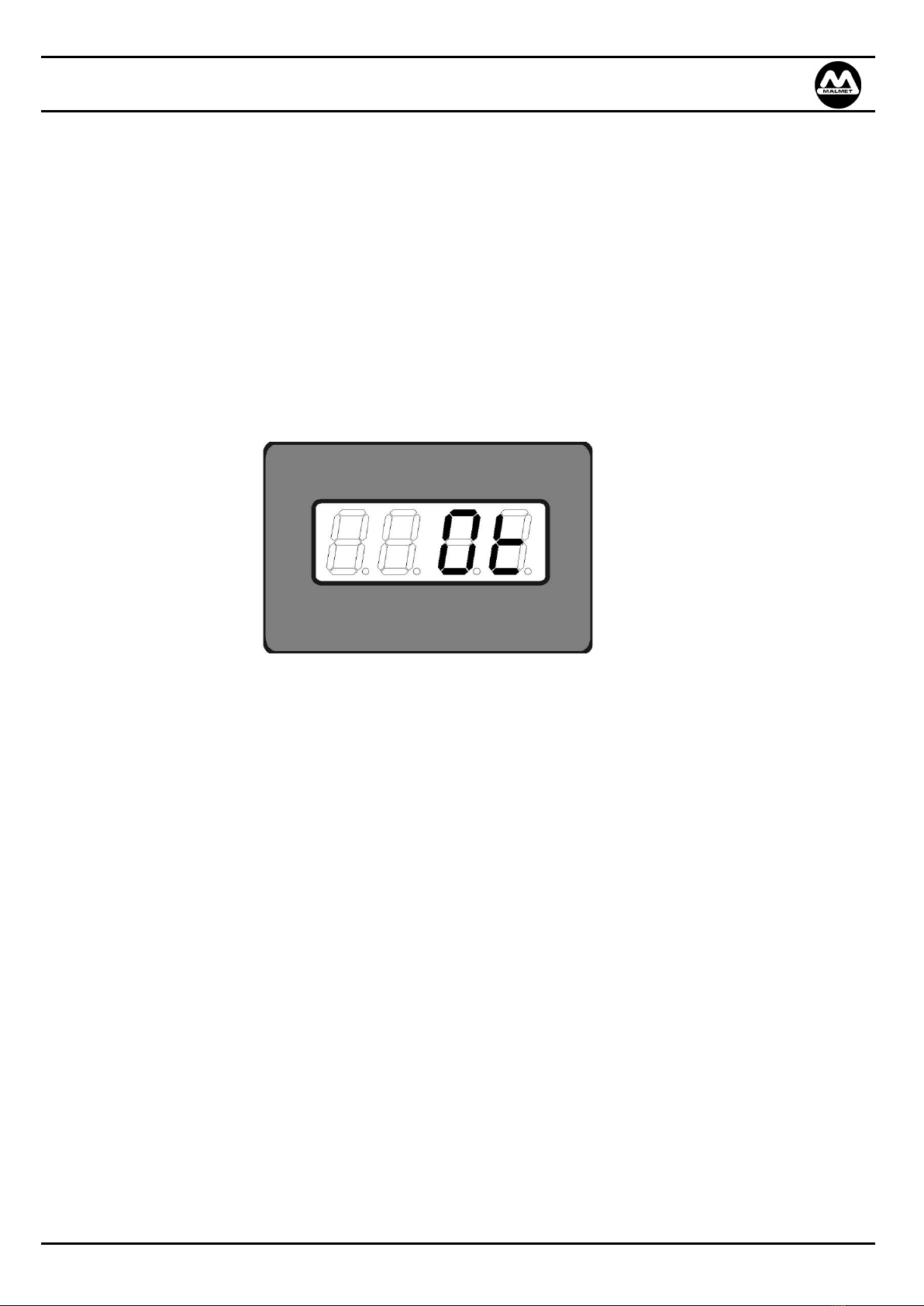
1.5 Temperature Cut Out
The device has a built in electronic over temperature cut out which will switch off the elements if the selected
temperature is exceeded by 5°C, and ‘Ot’ will flash on the display panel. (See Fig 1)
If the electronic cut out fails, a secondary safety bi-metallic cut out temperature switch will switch off the power
to the elements.
Fig 1
1.6 Temperature Sensor Plate
When new product is introduced into the cabinet the temperature of the fluid can be monitored using the
temperature sensor plate.
1. Place fluid container on the Fluid Sensor Plate located on the bottom shelf ensuring the sensor disc is
completely covered.
2. Wait two minutes for an accurate temperature reading to be obtained.
3. To view actual fluid temperature, via the main display board, press and hold down either of the up or
down temperature buttons.
Note 1: It can take an average of eight hours for a full load of fluid containers to reach required temperature.
This time may vary depending on the configuration of the load. It is recommended that the cabinet is
re-stocked at the end of each day.
Note 2: Rotation of stock is important, as once warmed, solution should be used within 14 days.

Fluid Warming Cabinet
Operation, Maintenance and Installation Manual
Issue 18 Page 7 Jun-23
2.0 Installation
Floor Bench Skirt
Floor Bench Skirt is factory fitted to the cabinet. To level, remove the four plastic plugs from the inside floor and
adjust the feet by turning the slotted screw head. Once the device is level, replace the plugs.
If the Floor-Bench Skirt is ordered separately to convert a warming cabinet, the conversion will take
approximately fifteen minutes and requires a screwdriver only. Carefully, place the warming cabinet on its back.
The base is pre-drilled with ten Nutsert holes. Using the screws supplied, fasten the Floor-Bench Skirt. Carefully,
stand the warming cabinet upright and level as above.
The front panel of the Floor-Bench Skirt is removable to clean under the warming cabinet.
Combination Cabinets
To level, remove the four plastic plugs from the inside floor and adjust the feet by turning the slotted screw
head. Once the warming cabinet is level, replace the plugs.
The front panel of the floor skirt is removable to clean under the warming cabinet.
Cabinet Stand
Cabinet Stand is factory fitted to the warming cabinet. To level, remove the front panel of the stand and adjust
the feet by turning the slotted screw-head. This panel can also be removed to clean under the warming cabinet.
If the stand is ordered separately to convert a warming cabinet, the conversion will take approximately fifteen
minutes and requires a screwdriver only. Carefully, place the warming cabinet on its back. The base is pre-
drilled with ten Nutsert holes. Using the screws supplied, fasten the stand. Carefully, place the warming cabinet
upright and level as above.
Combination Conversion Kit
This comprises a Floor-Bench Skirt and a Rear Joining Bracket. Conversion will take approximately fifteen
minutes and requires a screwdriver only. Carefully, place the bottom warming cabinet on its back. The base is
pre-drilled with ten Nutsert holes. Using the screws supplied, fasten the Floor-Bench Skirt. Carefully, stand the
warming cabinet upright.
Remove the 7 plugs (3 small and 4 large) on the top of the bottom warming cabinet, place the top warming
cabinet in position locating the bottom hinge bolts in the four large holes. Remove the two screws in the
warming cabinet that secure the slide out service tray and slide out as far as it will go. There are three securing
holes located inside the top of the service compartment. Using the screws supplied, fasten the warming cabinets
together and replace the service tray.
The back of both warming cabinets is pre-drilled with four Nutsert holes, using the screws supplied, fix the Rear
Joining Bracket into position. Place the warming cabinet in position and level.
Plugs must be replaced after levelling or the temperature control of the warming cabinet may be compromised.
Wall Mounted Cabinet
Wall Mounting Brackets are supplied for single 210 litre and 260 litre models. Secure the bracket to the wall,
ensuring it is level. It is recommended to use 4 (8mm x 50mm) long coach screws for stud position walls and
dyna bolts for solid walls.
Two people are required to lift the cabinet to the height of the Mounting Bracket, move the top of the warming
cabinet to the wall at approximately 45° and locate on the Wall Mounting Bracket. When secure swing the
bottom of the warming cabinet to the wall ensuring it is firmly pushed onto the wall bracket. To remove, reverse
this procedure.
CAUTION: Wall mounted fluid cabinet when fully loaded weighs approximately 143 kg. unloaded weight approximately 83
kg

Fluid Warming Cabinet
Operation, Maintenance and Installation Manual
Issue 18 Page 8 Jun-23
Warming Cabinets with Castors
All warming cabinets should be located on a level floor surface and should never be operated on a sloping
surface.
Check that all swivel wheels are in lock position.
Should the warming cabinet require to be moved, disconnect power plug from the GPO.
Risk Assessment
It is recommended a risk assessment is conducted by the user both prior to and after installation and any risks
identified mitigated to an acceptable level using the hierarchy of control;
https://commons.wikimedia.org/w/index.php?curid=55610678
Handling
Weights of Device: Net:47-195 kg Shipping: 57-210 kg Shipping with crating: 84-275 kg.
•Handling of the device to installation site must be with fork lift or hand pallet truck.
•Before unpacking device inspect carton for any damage relating to forklift forks and damage relating to
device falling over or for evidence of top loading
•After unpacking the device, inspect all external panels for damage.
•Remove the screws and brackets holding the device to the pallet.
•Follow your internal manual handling guidelines to manoeuvre the device off the pallet. The device can then
be placed into position by fork lift or hand pallet truck.
Disposal of Packaging
•Please dispose of packaging as per facility procedures or local government requirements.
Fluid Warming Cabinet
Operation, Maintenance and Installation Manual
Issue 18 Page 9 Jun-23
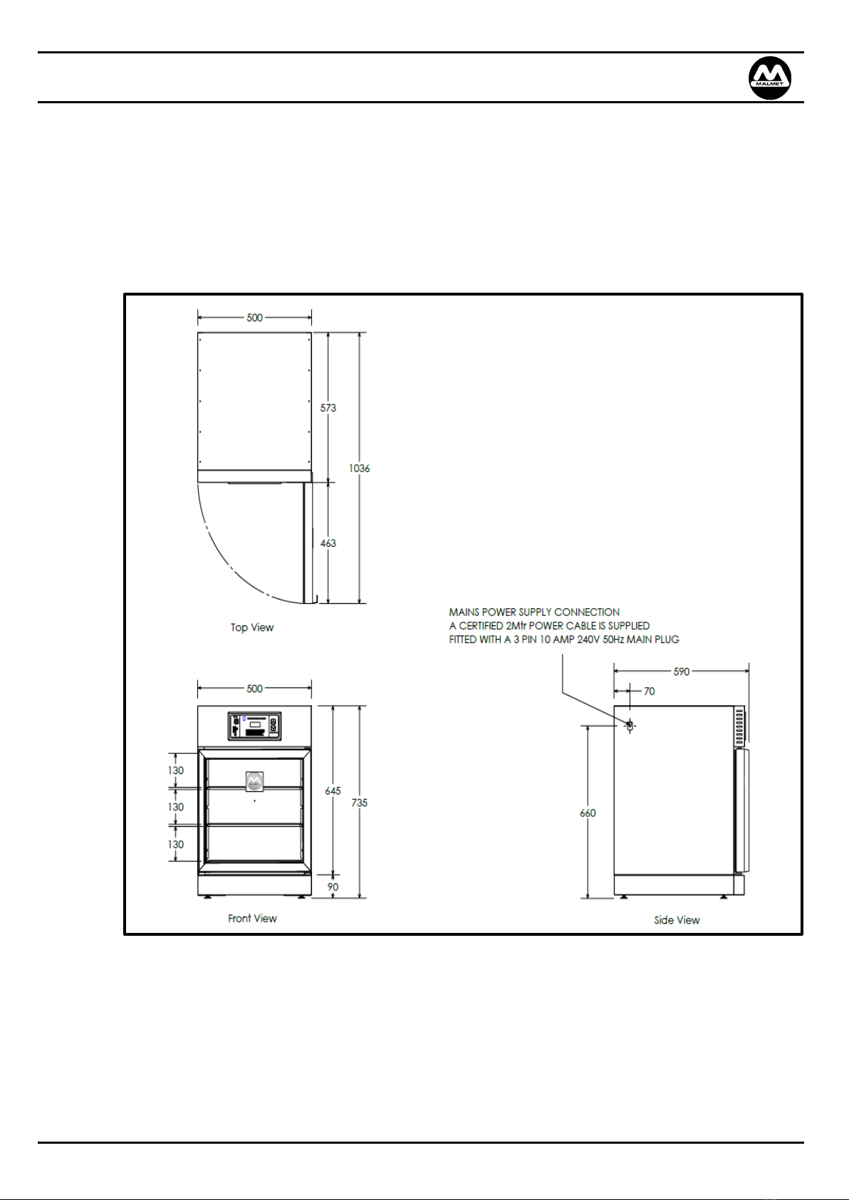
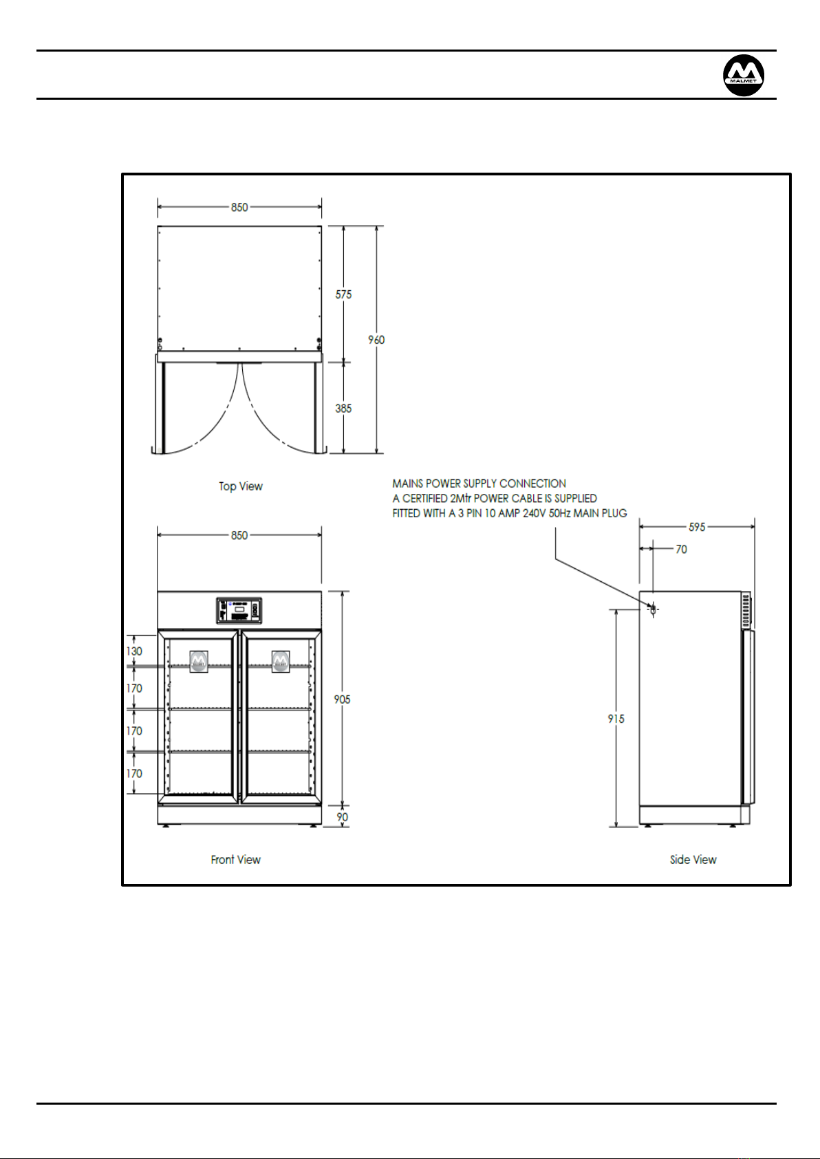
2.1 Service Connections
Electrical Connection –240 Volt 10 Amp
Plug into 10 Amp G.P.O.
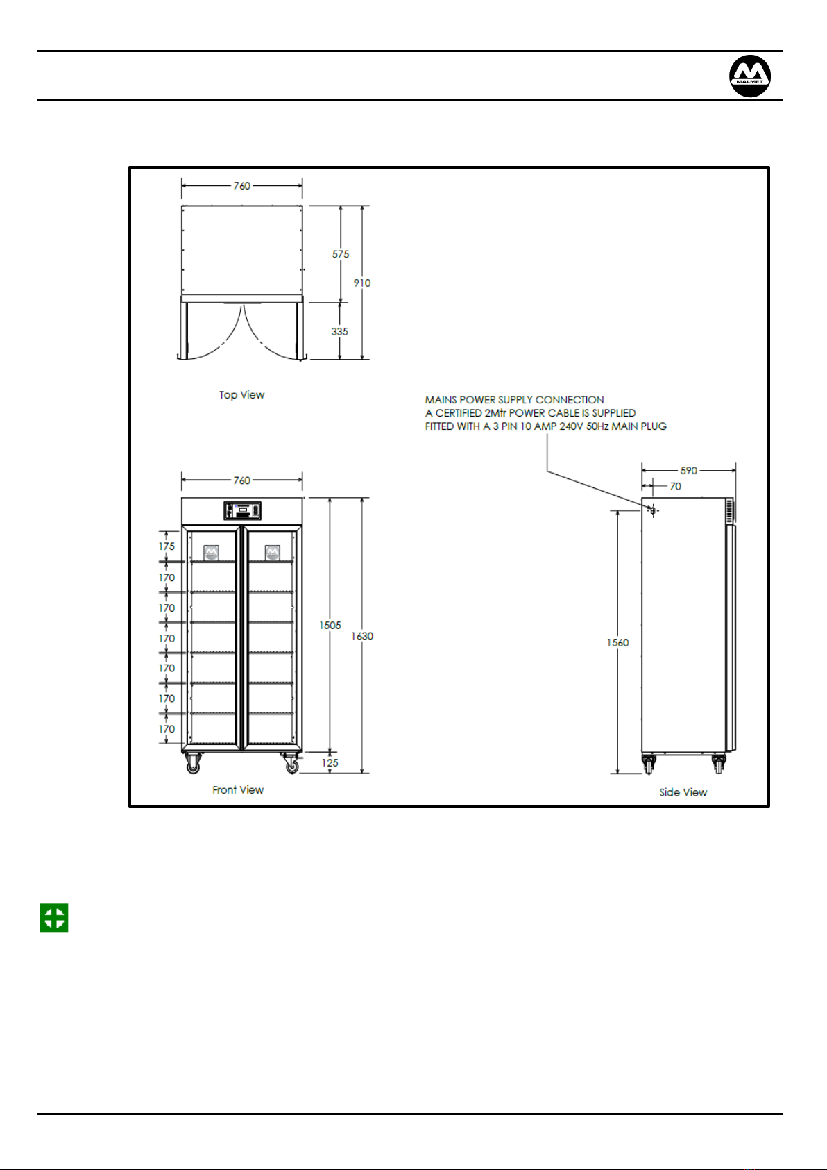
2.2 Device Dimension and Clearances
F105BT Fluid Warming Cabinet Bench Top

Fluid Warming Cabinet
Operation, Maintenance and Installation Manual
Issue 18 Page 10 Jun-23
F210FS Fluid Warming Cabinet Freestanding with Floor Skirt
Fluid Warming Cabinet
Operation, Maintenance and Installation Manual
Issue 18 Page 11 Jun-23
F260FS Fluid Warming Cabinet Freestanding with Floor Skirt
Fluid Warming Cabinet
Operation, Maintenance and Installation Manual
Issue 18 Page 12 Jun-23
F420C Fluid Warming Cabinet Freestanding on Castor
Note: This Blanket Warming Cabinet is not intended for use by persons (including children) with reduced
physical, sensory, or mental capabilities, or lack of experience and knowledge.
Children should be supervised to ensure they do not play with the Blanket Warming Cabinet.
If the supply cord is damaged, it must be replaced by the manufacturer or its service agent or a
similarly qualified person in order to avoid a hazard.

Fluid Warming Cabinet
Operation, Maintenance and Installation Manual
Issue 18 Page 13 Jun-23
3.0 Maintenance
3.1 Preventative Maintenance
Monthly Can be performed by trained operators or other authorised personnel.
1. Wipe out inside doors and chamber with a multipurpose cleaner, ensuring no residues remain
as this may cause oxidation of the surface.
2. Wipe over outside panels with stainless steel cleaner.
Annually To be performed by Malmet Technician or other authorised personnel.
1. Check electrical connections as per AS/NZS 3551:2012
2. Perform temperature calibration
•Insert calibrated thermometer
•Allow cabinet temperature to stabilise
•Compare cabinet display temperature to thermometer value & ensure discrepancy is within
+/- 2 ºC.
Devices should have regular Test and Tag procedures undertaken.
3.2 Replacement of Safety Devices
The following safety devices must be replaced and tested by a Malmet trained technician, failure to do so may
impair the protection by the device.
•Over Temperature Cut Out Switches
•Campini Cut-out
Information on replacement of these devices can be found in the Service Technicians Manual.

Fluid Warming Cabinet
Operation, Maintenance and Installation Manual
Issue 18 Page 14 Jun-23
3.3 Trouble Shooting Guide
Problem
Probable Cause
Suggested Remedy
Display not on or won’t turn on.
No Mains power supply.
Power point not turned on.
Display will not turn on.
Faulty display board.
Interconnecting harness failure.
Relay board fault.
Check power supply and lead
plugged in.
Check power switched on.
Press Standby button.
Switch off power supply at main
and Call for Service.
Display turns on.
(Runs for approximately ½ - 1
hour then turns off).
Fan failure.
Switch off power supply at main
and Call for Service.
Display is on but unit not heating.
Element failure.
Relay board failure.
Switch off power supply at main
and Call for Service.
Display indicates Ot
Fan Failure.
Element on. Continuously unable
to switch off. (Relay Board
Failure)
Switch off power supply at main
and Call for Service.
Display indicates O/C
Control Temperature Thermistor
is broken or unplugged.
Switch off power supply at main
and Call for Service.
Display on but unit cooling down.
Element failure.
Relay board failure.
Switch off power supply at main
and Call for Service.

Fluid Warming Cabinet
Operation, Maintenance and Installation Manual
Issue 18 Page 15 Jun-23
4.0 Technical Specifications
4.1 Device Specifications
Capacity –Single
(Litres of fluids)
105 Litre models
24 Litres maximum load
210 Litre models
45 Litres maximum load
260 Litre models
60 Litres maximum load
420 Litre models
105 Litres maximum load
Shelves –Single
105 Litre models
(3 shelves; 2 are adjustable)
Maximum load: 8 litres per shelf
210 Litre models
(3 shelves; 2 are adjustable)
Maximum load: 15 litres per shelf
260 Litre models
(4 shelves; 3 are adjustable)
Maximum load: 15 litres per shelf
420 Litre models
(7 shelves; 6 are adjustable)
Maximum load: 15 litres per shelf
Electrical Rating
Volts
240Vac
Phase / Hz
1 ph / 50Hz
Amps
2.8 Amps
Watts
0.6 kW
Environment operating conditions
Temperature
Relative Humidity
+10C to +25C
+30% to +70%
Electrical Connection
IEC right angle Power Cord with
3 Pin Plug
10 Amp (into standard GPO 240
Volt)
Hot Air Fan
Continuous operation
Ball bearings 230V 50 Hz
Elements
Circular Unfinned
Incoloy 840 sheathed 10mm
diameter tubular
Rated
240V 600 watt
Control PCB
Microprocessor Control Relay
PCB (SKCM325) Access via
compatible RS232
Overtemp Protection
Electronic cutout @ 5°C above set
point
Temperature Control
Incremental 1°C –50°C
Factory set at 37°C
Over-temp Protection
Software
5°C above set point
Secondary Overtemp Protection
Mechanical
Auto reset Bi-Metallic Disc 60°C
Materials
Doors
Bi-parting, double glazed with
powder coated frames
Cabinet
304/4 and 430D stainless steel
Environment conditions Transport
and Storage
Fragile Keep away from rain Do not stack
Fluid Warming Cabinet
Operation, Maintenance and Installation Manual
Issue 18 Page 16 Jun-23
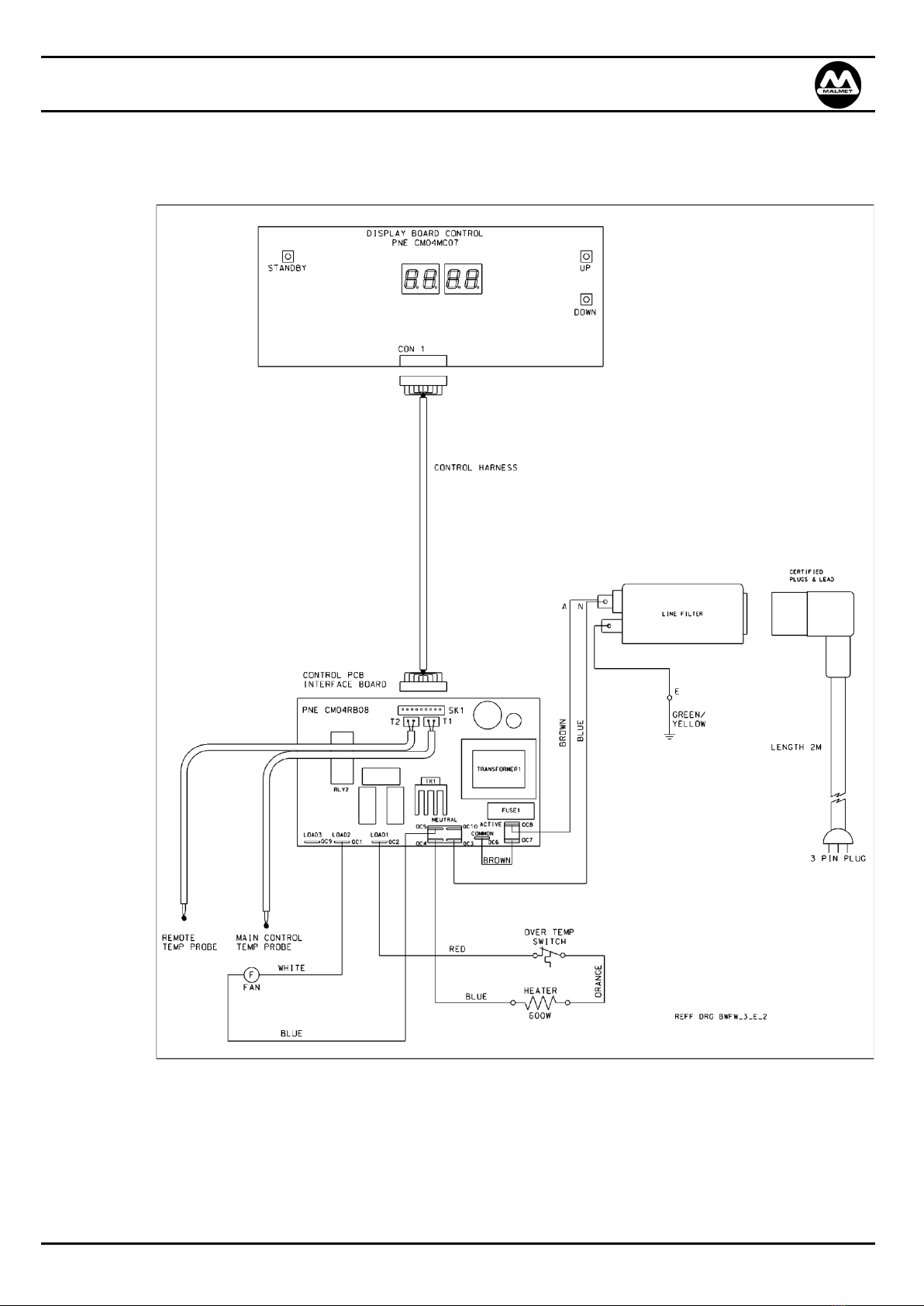
4.2 Wiring Diagram
Fluid Warming Cabinet
Operation, Maintenance and Installation Manual
Issue 18 Page 17 Jun-23
Warranty Statement
This warranty is provided, and operates in addition to, the statutory warranties Malmet (Australia) Pty Ltd
("Malmet") provides to any consumer under the Australian Consumer Law (if applicable) or by virtue of any other
applicable legislation.
Subject to the following conditions, we provide, from the date of purchase, the following warranty on Malmet
devices and spare parts for products manufactured by Malmet and sold in Australia:
•Functional components found within the device to be defective in workmanship or material will be repaired or
replaced free of charge subject to the periods of warranty specified in the table below.
•A decision regarding whether the defective components will be repaired or replaced will be determined at the
sole discretion of Malmet or its authorised agents or representatives.
•The structural warranty covers any structural components within the device, which fail to perform their
intended function due to faulty manufacture or deterioration within the warranty period.
•Parts replaced in devices under warranty are warranted for the balance of the original warranty period for
that device.
Malmet Devices
Device Components
Parts & Labour
Structural Guarantee
2 Years from Date of Purchase
All other components
2 Years from Date of Purchase
Malmet Spare Parts
1 Year from Date of Purchase
The installer is responsible for the correct installation, start up and demonstrating the operation of the product. They
are also responsible for issuing the relevant certificates of compliance (these may differ from state to state).
CONDITIONS AND EXCLUSIONS
•Device must be installed and commissioned according to Malmet’s instructions (outlined in Malmet Operation,
Maintenance and Installation Manual) and operated to the purpose it was designed.
•Device must be serviced as instructed in the Operation, Maintenance and Installation Manuals.
•To the extent permitted by law, this warranty shall not cover damage, malfunction or failure resulting from
accident, misuse or misapplication, improper or unauthorised repair, neglect or modification or use of
unauthorised replacement parts or accessories, inclusive of detergent, or improper voltage. The warranty may be
void if the serial number is removed or altered.
•Parts damaged in transit back to Malmet Leeton due to poor packaging could result in warranty claim being
rejected in part or in full.
•Any part tampered with or which has been altered by unauthorised repairs and/or modifications will be rejected
under a warranty claim to the extent permitted by law (to the extent the Australian Consumer Law applies,
Malmet will assess the extent to which the tampering or unauthorised repairs contributed to the failure).
•Reasonable access must be allowed for maintenance. If any additional equipment is needed to provide access to
the device, this must be provided (and paid for) by the owner.
•It is the owner's responsibility to provide safe access to the device. Malmet, or any of its authorised service agents,
may refuse to perform maintenance or warranty work if access is unsafe, as determined by Malmet or any of its
authorised service agents acting reasonably.
•Should a warranty claim be rejected you will be advised in writing with a full explanation of our reasons.

Fluid Warming Cabinet
Operation, Maintenance and Installation Manual
Issue 18 Page 18 Jun-23
•Malmet have a Warranty Claim Procedure that is fair to our customers and provides an efficient system of
replacement and/or repair of faulty parts. If at any time you believe we are not meeting our commitment to you
•To the extent permitted by law, no responsibility will be accepted for outside elements including, but not limited
to storms, pest and vermin that may cause damage to the device.
•To the extent permitted by law, no responsibility will be accepted for damage incurred as a result of, or incidental
to, electrical surges or brown outs or for any other consequential damages.
•If there is no certificate of compliance for plumbing or electrical, Malmet reserves the right to refuse service on
non-compliant installations.
•To the extent permitted by law, claims for damage to contents, carpet, ceilings, foundations or any other
consequential loss either direct or indirect resulting from, power spikes, incorrect operation, incorrect installation,
faulty product or any other cause, are excluded.
•This warranty, and to the extent permitted by law, any warranties owed by Malmet under the Australian
Consumer Law or other applicable legislation, are not transferrable and cannot be sold, assigned or transferred in
any other way from the purchaser to any other person.
•To the extent permitted by law, unauthorised use of any parts that were not supplied or approved for use in the
applicable device by Malmet will result in this warranty and any warranty claims applicable to that device being
void.
•Warranty labour (service work) shall not include devices located outside of city metropolitan areas of Melbourne,
Sydney, Adelaide, Perth and Brisbane. Costs outside these areas shall be borne by the owner. The owner shall be
notified of this prior to the warranty call out.
•Warranty labour (service work) shall be performed during normal business hours (Monday –Friday 7am –4pm),
excluding public holidays.
•Warranty labour (service work) performed outside of normal business hours, shall be charged at Malmet’s or its
authorised representative or agent’s standard after-hour labour rates.
•Warranty relating to spare parts covers parts only and does not include any associated labour costs.
To the extent permitted by law, a charge will be made for work done or a service call made where:
•There is no fault apparent with the device, as determined by Malmet or its authorised representative or agent
acting reasonably.
•The defective operation of the device is due to failure of electricity or water supply.
•Defects are caused by neglect, incorrect application, abuse or by accidental damage of the device.
•An unauthorised person has attempted to repair the device.
•Harsh environmental situations including, but not limited to, water quality that may cause the water tank damage
cannot be covered under this warranty

Fluid Warming Cabinet
Operation, Maintenance and Installation Manual
Issue 18 Page 19 Jun-23
HOW TO MAKE A CLAIM UNDER THIS WARRANTY
If you believe there is a defect in a device you have purchased from Malmet, you must notify Malmet in writing of
such defect, by sending an email (Notice of Defect) to info@malmet.com.au prior to the expiration of the applicable
warranty period set out in this warranty.
For the avoidance of doubt, Malmet must receive your Notice of Defect prior to the expiration of the warranty period.
To the extent permitted by law, Malmet will not reimburse you for any expense you incur in claiming or attempting to
make a claim for repair or replacement of a component under this warranty.
Please complete details below:
Date Purchased:
Warranty Expiry Date:
Sold To:
For Service Contact:
PROOF OF PURCHASE
Please retain your proof of purchase (receipt, invoice or commissioning certificate is accepted).
E.&O.E.
In the interest of continued product improvement, Malmet reserves the right to alter specifications without notice.
AUSTRALIAN CONSUMER LAW DISCLAIMER (APPLIES ONLY TO THE EXTENT YOU ARE A ‘CONSUMER’ WITHIN THE
MEANING OF THE AUSTRALIAN CONSUMER LAW):
Malmet goods come with guarantees that cannot be excluded under the Australian Consumer Law. You are entitled
to a replacement or refund for a major failure and for compensation for any other reasonably foreseeable loss or
damage. You are also entitled to have the goods repaired or replaced if the goods fail to be of acceptable quality and
the failure does not amount to a major failure.
This manual suits for next models
24
Table of contents
Other Malmet Laboratory Equipment manuals


Popular Laboratory Equipment manuals by other brands

Mocom
Mocom B Futura-17 User's quick start guide

Resodyn
Resodyn Manual Vacuum Control Module Installation and user manual

Agilent Technologies
Agilent Technologies Small RNA Kit quick start guide

Leica BIOSYSTEMS
Leica BIOSYSTEMS HistoCore BIOCUT Instructions for use

Thermo Scientific
Thermo Scientific thermoscientific Vanquish Pumps C operating manual

PIKE Technologies
PIKE Technologies GladiATR manual


