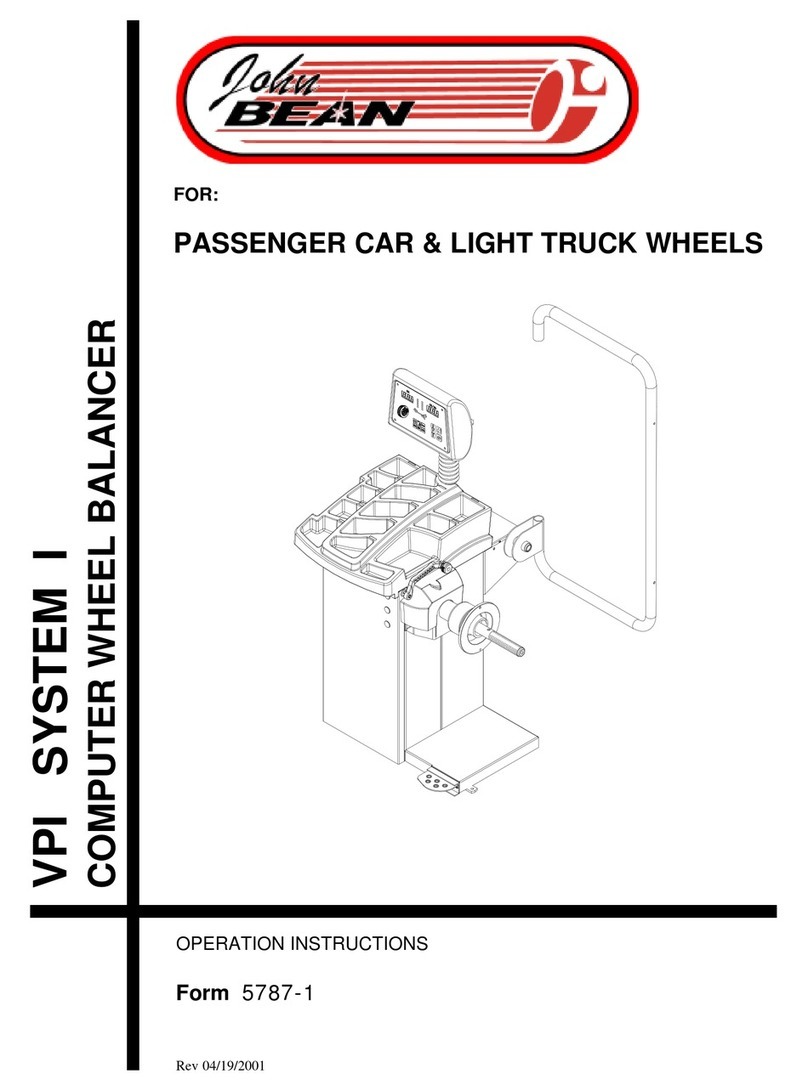
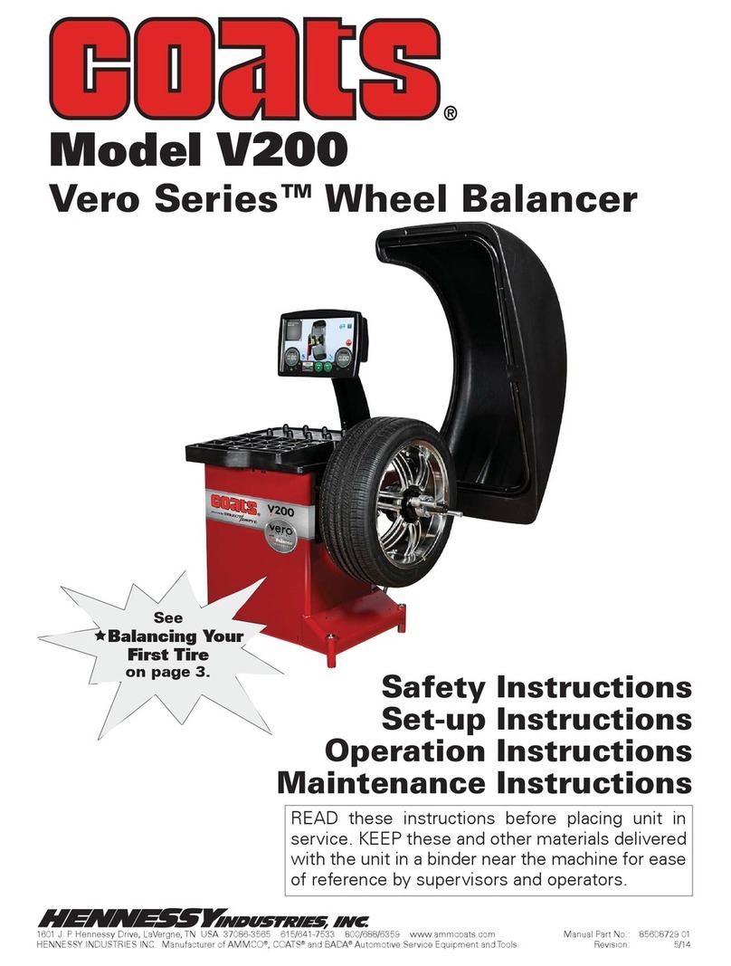
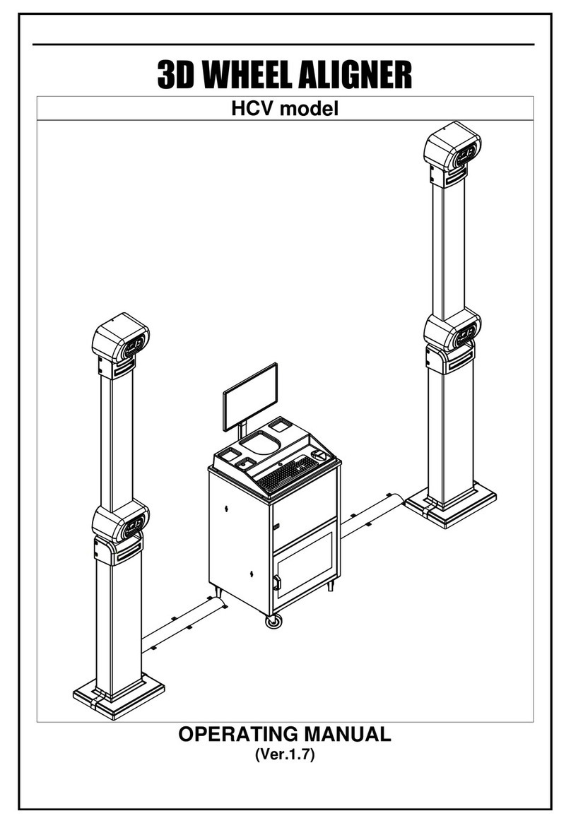
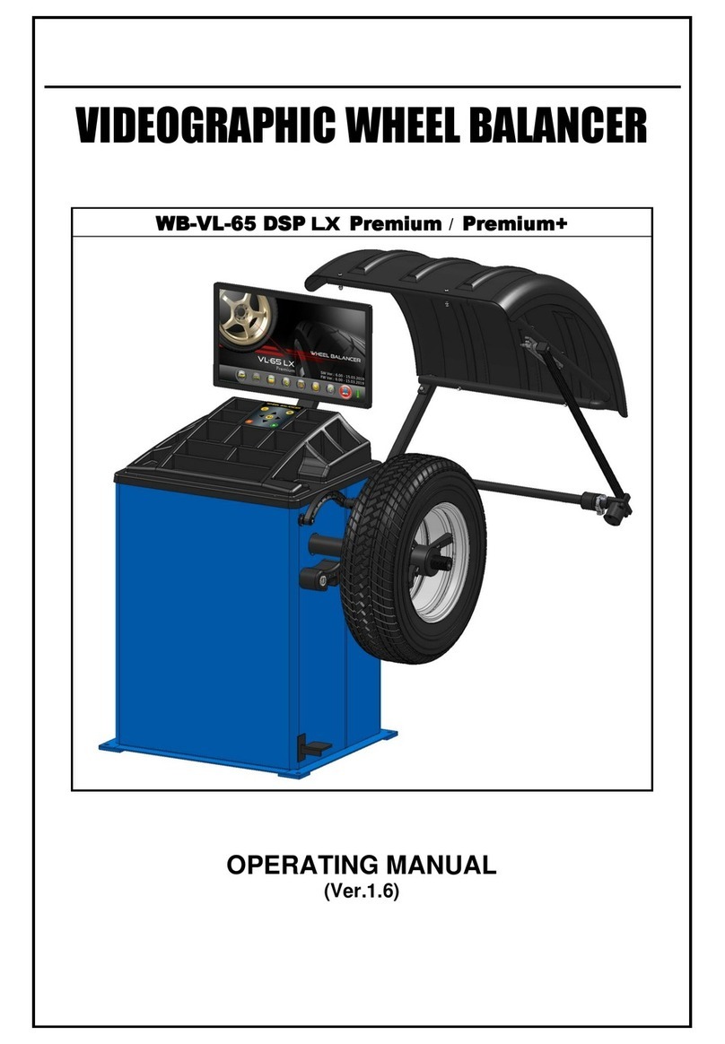
MANATEC Fox 3D Smart Mobile PT User manual

3D WHEEL ALIGNER
PIT (PT) model
DRIVE THROUGH (DT) model
VARIABLE HEIGHT (VH) model
IN-LIFT model
14
AUTOMATIC VARIABLE HEIGHT (AutoBoom) model
AutoBoom AutoBoom X AutoBoom V4
With Cabinet
SERVICE MANUAL
(Ver.1.8)

INDEX Page No.
1. WARRANTY –STATUTORY CLAUSE 1
2. INSTALLATION REQUIREMENTS 2
2.1. POWER REQUIREMENT 2
2.2. SPACE REQUIREMENTS 3
2.2.1. ALIGNMENT PIT DIMENSIONS (Applicable only for PT / VH / Wall mount models) 3
2.2.2. ALIGNMENT LIFT DIMENSIONS (Applicable only for VH / Wall mount / Auto Boom / In-Lift) 8
3. PACKING IDENTIFICATION 17
4. INTEGRATION 21
4.1. EQUIPMENT INTEGRATION 21
4.1.1. VERTICAL COLUMN 21
4.1.2. HORIZONTAL BEAM (NA for In-Lift model) 24
4.1.3. MAIN CABINET (NA for In-Lift model) 25
4.1.4. PC ACCESSORIES COLUMN (For Drive Through model) 25
4.1.5. PC ACCESSORIES COLUMN (For In-Lift model) 26
4.2. FOUNDATION 26
4.2.1. VERTICAL COLUMN (Applicable only for PT / VH / AVH models) 26
4.2.2. WALL MOUNTING BRACKET 28
4.3. COMPUTER & PERIPHERALS INTEGRATION 29
4.3.1. PT / VH / AVH MODEL 29
4.3.2. VH / AVH MODEL WITH MAIN CABINET 29
4.3.3. DRIVE THROUGH MODEL 29
4.3.4. IN-LIFT MODEL 29
4.4. ROUTING 30
4.4.1. PT / VH MODELS 30
4.4.2. AVH MODEL 31
4.4.3. DRIVE THROUGH MODEL (USB3.0 configurations) 33
4.4.4. IN-LIFT MODEL (USB3.0 configurations) 34
5. DESCRIPTION OF MAIN PARTS 35
5.1. CAMERA BEAM / COLUMN 35
5.1.1. CAMERA (LH & RH) 35
5.1.2. IR LED BOARD 36
5.1.3. LED DRIVER BOARD & HUB BOARD 36
5.2. INTERFACE BOX 37
5.2.1. EMI FILTER BOARD (applicable only for PT / VH / In-Lift models) 39
5.2.2. SMPS 39
5.2.3. MOTOR CONTROL BOARD (applicable only for AVH model) 39
5.2.4. MOV BOARD (applicable only for AVH model) 39
5.3. TARGET PLATE 39
5.4. VERTICAL COLUMN (AVH / AutoBoom model) 40
5.5. DESKTOP COMPUTER 42
6. SOFTWARE INSTALLATION 43
6.1. ALIGNMENT PC SOFTWARE 43
6.1.1. STEP-1 : Windows OS installation 43
6.1.2. STEP-2 : Wheel Aligner 3D Setup installation 48
6.1.3. ALIGNMENT PC SOFTWARE UPDATE 55
6.2. INTERNATIONAL VEHICLE DATA (Refer scope of supply) 56
7. CALIBRATION 57
7.1. BEAM INSTALLATION 57
7.2. FLOOR CALIBRATION 58
7.3. SENSOR (DUAL AXIS) CALIBRATION 58
7.4. CAMERA CALIBRATION 60
7.4.1. FOUR SHAFT CALIBRATION 60
7.4.2. SINGLE SHAFT CALIBRATION (Applicable for the Ver.3.06 & below only) 72
7.4.3. TARGET PLATE CALIBRATION (Only for spare replacement) 78
7.5. CALIBRATION CHECK 79
7.6. CALIBRATION CERTIFICATE 79
7.7. AUTOBOOM TEST 79
7.8. MANUAL (SELF) CALIBRATION 79

8. SYSTEM SETTINGS 80
8.1. CAMERA TESTING 81
8.2. CAMERA CONFIGURATION (Only for spare replacement) 81
8.3. CAMERA VISION SETTING (Only for spare replacement) 82
8.4. LEFT / RIGHT STEERING WHEEL SETTING 82
8.5. DISTRIBUTOR INFORMATION 82
9. PARTS REPLACEMENT PROCEDURE 83
9.1. HORIZONTAL BEAM 83
9.1.1. CAMERA (LH & RH) 83
9.1.2. IR LED BOARD 85
9.1.3. LED DRIVER BOARD & HUB BOARD 85
9.2. INTERFACE BOX 86
9.2.1. EMI FILTER BOARD / MOTOR CONTROL BOARD 86
9.2.2. SMPS 87
9.2.3. MOV BOARD (Applicable only for AVH model) 87
9.3. VERTICAL COLUMN (Applicable only for AVH model) 88
9.3.1. POWER NUT 88
9.3.2. BELT 88
9.4. TARGET PLATE 88
9.5. PERSONAL COMPUTER 88
10. DIAGRAMS 89
10.1. BLOCK DIAGRAM 89
10.2. WIRING DIAGRAM 90
10.2.1. PT / VH MODEL 90
10.2.2. AVH MODEL 92
10.2.3. IN-LIFT MODEL 94
11. TROUBLE SHOOTING 96
11.1. HARDWARE TROUBLE SHOOTING 96
11.2. MECHANICAL TROUBLE SHOOTING 98
11.3. SOFTWARE TROUBLE SHOOTING 98
11.4. MIS-ALIGNMENT TROUBLE SHOOTING 99

Ref.: 3DWA - SM Ver.1.8 1
1. WARRANTY –STATUTORY CLAUSE
The equipment is provided with Warranty for one year from the date of installation or thirteen
months from the date of despatch whichever is earlier, against any manufacturing defect. The
Warranty is subjected to the following conditions:
1. Ensure that proper power supply with protective Earthing is provided to the equipment
through uninterruptible Power Supply (UPS). Any high voltage may damage the
components, leading to system failure or electrical hazards.
Power supply:
230V operation: Single Phase, 230V AC ± 10%, 50 Hz + N + PE (or)
110V operation: Single Phase, 110V AC ± 10%, 60 Hz + N + PE
110V operation: For Automatic Variable Height (AVH) model –Single Phase, 110V
AC ± 10%, 60 Hz + N + PE
(The Potential difference between N –Neutral & PE - Protective Earth should be
below 3V)
Laser printer should be connected in a separate power supply. Machine power
socket should not be used for this purpose
Warranty ceases if this condition is not satisfied
2. Power supply to the equipment should be connected only through a CVT of 1KVA
capacity and then through an UPS of minimum 1KVA capacity with AVR (Automatic
Voltage Regulator) circuit. The system must be shut down before the UPS power trip
OFF. Failing to comply may lead to software corruption.
Warranty ceases if this condition is not satisfied
3. Do not attempt to open or service the equipment under any circumstances by un-
authorised personnel. Risk of electric shock may happen. Only authorised / qualified
service personnel should trouble shoot the equipment.
Warranty ceases if the equipment is opened/tampered or serviced by un-authorised
personnel
4. Warranty ceases if this equipment is used for any purpose other than intended use.
5. The equipment must be installed Indoor away from Sunlight, rain / moist areas
Warranty ceases if the equipment is exposed to direct Sunlight, Rain / Water
6. Do not attempt to load any other Application software (Audio, Video etc.) under any
circumstances, other than the alignment program loaded in the Factory.
Warranty ceases if the system is loaded with any other Application software
7. If transportation, lifting, unpacking, installation, assembly, start up, testing, repair and
maintenance have been performed by un-authorised personnel, the manufacturer shall
not be responsible for injury to personnel or damage to objects.
8. DO NOT remove or modify any parts of the equipment as this could compromise the
equipment's intended use. For any modifications / repairs consult the Manufacturer.
9. The Vehicle specification data must be entered by End user only. MANUFACTURER IS
NOT RESPONSIBLE FOR ANY INCORRECT OR INCOMPLETE VEHICLE
SPECIFICATIONS ENTERED INTO THE SYSTEM. No claim is entertained for any
damage or loss.
10. Follow the Alignment lift manufacturer‟s safety recommendations when lifting a vehicle.
MANUFACTURER IS NOT LIABLE FOR ANY DAMAGES CAUSED due to non-
compliance
11. Make the warranty registration by duly signing the counterfoil of the Warranty card sent
along with the equipment.
Manufacturer does not warrant third party products / software added to our Wheel aligner
through our Factory integration system. The below listed Third party products / peripherals /
software are covered under the warranties provided by the respective OEM. Third party
manufacturer's warranty may vary from product to product. Consult the respective product
documentation for warranty information:
1. Desktop computer with Monitor
2. Printer
3. Keyboard
4. Mouse
5. Multimedia speakers
6. Operating system software
Ref.: 3DWA - SM Ver.1.8 2
2. INSTALLATION REQUIREMENTS
Wheel aligner installation should be done only by qualified Service personnel.
Before attempting installation, read these instructions thoroughly and understand the tasks
involved. Review all the requirements of installation to avoid oversights resulting in revenue
loss, and lost customer confidence.
Ensure the environment is conducive for optimum performance of imaging alignment.
3D Wheel aligner can be installed as conventional wheel aligners; however there are unique
considerations which must be addressed. 3D Wheel aligner normally requires zero offset
calibration at the installation place.
Provision of handling means such as Forklifts etc. is the owner's responsibility
Procure the necessary tools to do a quality job
Perform the installation safely by observing all precautions associated with the task at
hand.
Ensure that the Rack/Lift is safe and the lock mechanisms are secured. Check runways
are co-planar at all heights & it is relatively leveled for ease of push-Pull Runout. Check
the Turn tables are free from binding and rotates freely.
The following accessories and tools are required for the proper installation of the
equipment:
Screw drivers, Spanner set and Allen key set
Measurement Tape –5 metre
Marker / Chalk liner - for marking
0° Sprit Level
Strip cutter - to Open Carton Banding
knife –for opening Cartons
Plastic cable Ties –for proper routing of cables
Multi-meter –for verifying supply voltage
0.5kg. Hammer - Set Anchor Bolts
Hammer Drill and 12mm Drill bit
Calibration kit
Glass Cleaner(Cleaning agent) - for cleaning Targets after installation, if necessary
Adjustable Wrench
Instruction stickers
Pendulums –2 Nos.
Water tube level -5meter
Shims (required quantities) –0.5mmT, 1.0mmT, 1.5mmT & 2.0mmT
2.1. POWER REQUIREMENT
Stabilised (AVR) UPS 230V AC ± 10%, 1φ, 50 Hz + N + PE (or)
Stabilised (AVR) UPS 110V AC ± 10%, 1φ, 60 Hz + N + PE for 110V operation
Stabilised (AVR) UPS 110VAC ±10%, Single Phase, 60Hz +N +PE (For AVH model)
Supply should be connected only through a CVT of 1KVA capacity and then through an
UPS of minimum 1KVA capacity with AVR (Automatic Voltage Regulator) circuit using
a CE certified Two Pole, Type C, 6A MCB (For AVH 110V model, Two pole, Type C,
10A MCB). Proper Earthing must be provided. Also ensure that Live phase is on the
right side point of the wall socket.
Neutral to Line Voltage should be 230V AC ±10% (or) 110V AC ±10%
Line to Earth voltage should be 230V AC ±10% (or) 110V AC ±10%
Neutral to Earth leakage should be less than 3V AC
It is strongly recommended to use CVT & UPS (with AVR) for the aligner. Printer
should not be connected to UPS & separate power supply to be made.

Ref.: 3DWA - SM Ver.1.8 3
2.2. SPACE REQUIREMENTS
Installation area should have roof. The front space from the wall to the rotary
plate is 3.5 meter.
Floor should be of good concrete flooring and should be leveled surface.
Ensure that the floor adequately supports the Rack / Rail to withstand vehicle
load. Ensure the Turn table plate pits are leveled & Rear wheel sliders are
properly seated.
Proof of safe floor load capacity is the owner's responsibility
The clearances from side walls and roof should be adequate for the operator to
move around and perform wheel alignment / maintenance.
Alignment can be carried out either on Alignment pit or using Alignment lift.
Choice of suitable alignment platform is the owner's responsibility
2.2.1. ALIGNMENT PIT DIMENSIONS (Applicable only for PT / VH / Wall mount
models)
In case of Pit model, the Rotary plate top surface and Vertical column
base resting surface should be equal
Pit for Rotary plates and Rear wheel sliders are necessary to carry out
alignment. Both the pits should be in the same plane. However the main pit is
intended only for the operator to go underneath the vehicle easily and carryout
the required corrections. The length of the main pit can be made depending
upon the availability of space. The Rotary plate / Slider plate locating pit can
be finished with Granite or Marble purely by owner's choice.
Slider & its pit are not necessary for Heavy Commercial Vehicles
(HCV). However alignment pit with provision for Slider placement can
be used for alignment of Light Commercial Vehicle (LCV) using the
same pit
Choice of finish of pit is the owner's responsibility
A Rail using MS flat (50 mm x12 mm) for Trolley should be partly embedded
on the edge of main pit with 15mm height from floor level. This is required for
placing the Jack over the moving trolley platform to lift the vehicle while
carrying out Runout. A centralised single Hydraulic jack or Dual pneumatic
jack is recommended.
The floor level between the Left and Right rotary plate pits should be
same. The area adjoining the Main pit (except Rotary plate & Slider
pits) should be maintained at even level
The surface over which Rotary plates are kept must be perfectly leveled using
Spirit level. Also, perfect leveling must be ensured on both the sides of pit.
Otherwise it will affect the alignment results.

Ref.: 3DWA - SM Ver.1.8 4
PIT DIMENSIONS –Max. Wheel base –3.2 & 4metre (For PT model)
WHEEL BASE TABLE:
*
OVERALL PIT DIMENSIONS (19' x 12')
LENGTH : 5795 (19')
WIDTH : 3660 (12')
SQUARE
SPIRIT LEVEL
'B'
ROTARY PLATE
CENTRE
SECTION – AA
DETAIL – B
ROTARY PLATE
DEPTH: 50mm
ROTARY PLATE
DEPTH: 50mm
STEPS TO GO
DOWN TO PIT
STEPS TO GO DOWN TO THE PIT
1. RAIL FOR TROLLEY – 50x12mm (2'x½') - MAT'L: M.S FLAT
THE RAIL SHOULD BE PARTLY EMBEDDED IN THE GROUND
THE HEIGHT OF THE RAIL FROM THE FLOOR LEVEL SHOULD BE 15mm (5/8")
2. STEPS TO GO DOWN TO THE PIT
3. PIT DEPTH – 1524mm (5')
REAR WHEEL
MAX. WHEEL BASE
REAR WHEEL
MIN. WHEEL BASE
FRONT WHEEL
CAMERA DISTANCE
WHEEL BASE
LEVEL THE PIT DIAGONALLY
LEVEL THE RECESSES OF BOTH ROTARY
PLATE & SLIDER
MAX. WHEEL SLIDER OVERALL PIT DIMN. OVERALL PIT DIMN
BASE SIZE LENGTH WIDTH
NOTE:
1. U.O.S – ALL DIMENSIONS ARE IN mm
2. FLOOR/PLATFORM LEVEL TOLERANCE ALLOWED
SHOULD BE LESS THAN 2mm
3. 4m WHEEL BASE PIT DIMN REF. WHEEL BASE TABLE
4. AFTER PLACING THE LONGER SLIDER (1500mm LENGTH) IN THE # INDICATED 2400mm LENGTH RECESS, REMAINING 900mm
LENGTH HAS TO BE FILLED BY METAL SPACER (875x600x50)
5. * - DISTANCE BETWEEN CAMERA & TURN TABLE CAN BE ALTERED FROM 2000 – 2400mm BASED ON THE AVAILABILITY OF SPACE
GROUND
LEVEL
STRAIGHT FLAT
SlNo. Description
#
#
LONGER
SLIDER
DEPTH: 50mm
LONGER
SLIDER
DEPTH: 50mm
Fig. 1

Ref.: 3DWA - SM Ver.1.8 5
PIT DIMENSIONS –Max. Wheel base –3.2 & 4metre (For DT model)
Fig. 2
Set the verticality of Camera mounted Vertical columns using Jack
screws provided in the Master base plate

Ref.: 3DWA - SM Ver.1.8 6
PIT DIMENSIONS –Max. Wheel base –3.2 & 4metre (For VH model)
##
#
*
*
Fig. 3

Ref.: 3DWA - SM Ver.1.8 7
PIT DIMENSIONS –Max. Wheel base –3.2 & 4metre (For Wall mount model)
#
#
*
OVERALL PIT DIMENSIONS (17.8' x 12')
LENGTH : 5428 (17.8')
WIDTH : 3660 (12')
SQUARE
SPIRIT LEVEL
STRAIGHT FLAT
'B'
ROTARY PLATE
CENTRE
SECTION – AA
DETAIL – B
ROTARY PLATE
DEPTH: 50mm
ROTARY PLATE
DEPTH: 50mm
STEPS TO GO
DOWN TO PIT
BRACKET PITCH DETAIL
STEPS TO GO DOWN TO THE PIT
LONGER
SLIDER
DEPTH: 50mm
LONGER
SLIDER
DEPTH: 50mm
1. RAIL FOR TROLLEY – 50x12mm (2'x½') - MAT'L: M.S FLAT
THE RAIL SHOULD BE PARTLY EMBEDDED IN THE GROUND
THE HEIGHT OF THE RAIL FROM THE FLOOR LEVEL SHOULD BE 15mm (5/8")
2. STEPS TO GO DOWN TO THE PIT
3. PIT DEPTH – 1524mm (5')
SlNo. Description
SPACE INDICATED FOR SLIDER
IN HIDDEN LINE IS OPTIONAL
TILT ANGLE
(A)
CONCRETE/STRONG
BRICK WALL
FOR 6" DEPTH
REAR WHEEL
MAX. WHEEL BASE
REAR WHEEL
MIN. WHEEL BASE
FRONT WHEEL
CAMERA HEIGHT (H)
BRACKET PITCH
HEIGHT (P)
CAMERA DISTANCE (D)
WHEEL BASE (WB)
WHEEL BASE TABLE:
CAMERA VARIABLE HEIGHT FIXING & DISTANCE
LEVEL THE PIT DIAGONALLY
LEVEL THE WALL MOUNTING BRACKET
LEVEL THE RECESSES OF BOTH ROTARY PLATE
& SLIDER
MAX. WHEEL SLIDER OVERALL PIT DIMN. OVERALL PIT DIMN
BASE SIZE LENGTH WIDTH
TITLE CAMERA BRACKET CAMERA TO WHEEL
ANGLE HEIGHT PITCH ROTARY PLATE BASE
(A) (H) HEIGHT (P) DISTNACE (D) (WB)
NOTE:
1. U.O.S – ALL DIMENSIONS ARE IN mm
2. FLOOR/PLATFORM LEVEL TOLERANCE ALLOWED SHOULD BE LESS THAN 2mm
3. 4m WHEEL BASE PIT DIMN REF. WHEEL BASE TABLE
4. AFTER PLACING THE LONGER SLIDER (1500mm LENGTH) IN THE # INDICATED 2400mm LENGTH RECESS, REMAINING 900mm
LENGTH HAS TO BE FILLED BY METAL SPACER (875x600x50)
5. * - DISTANCE BETWEEN CAMERA & TURN TABLE CAN BE ALTERED FROM 2000 – 2400mm BASED ON THE AVAILABILITY OF SPACE
GROUND
LEVEL
Fig. 4

Ref.: 3DWA - SM Ver.1.8 8
2.2.2. ALIGNMENT LIFT DIMENSIONS (Applicable only for VH / Wall mount / Auto
Boom / In-Lift models)
Ensure that the rack/lift is safe and the lock mechanisms are secured.
Check runways are co-planar at all heights & it is relatively leveled for
ease of push-Pull Runout. Check the Turn tables are free from
binding and rotates freely
The Platform level should be same diagonally between the Left and
Right rotary plates
The Lift platform level and Vertical column base level should be same
while the lift is in closed condition
SCISSOR LIFT DIMENSIONS –Max. Wheel base –4 metre (For VH model)
Fig. 5

Ref.: 3DWA - SM Ver.1.8 9
SCISSOR LIFT DIMENSIONS –Max. Wheel base –4 metre (For Wall mount
model)
*
NOTE:
1. U.O.S – ALL DIMENSIONS ARE IN mm
2. FLOOR/PLATFORM LEVEL TOLERANCE ALLOWED SHOULD BE LESS THAN 2mm
3. * - DISTANCE BETWEEN CAMERA & TURN TABLE CAN BE ALTERED
FROM 2000 – 2400mm BASED ON THE AVAILABILITY OF SPACE
LEVEL THE FRONT & REAR OF A SINGLE
PLATFORM
LEVEL THE TWO PLATFORMS
LEVEL THE PLATFORMS DIAGONALLY
REAR WHEEL
MAX. WHEEL BASE
REAR WHEEL
MIN. WHEEL BASE
FRONT WHEEL
(MAX. WHEEL BASE)
WHEEL BASE (WB)
TO BE VARIED DUE TO LIFT & RAMP DIMN.
LIFT CENTRE LINE
WORKING AREA
MINIMUM ROOF HEIGHT – 14'
LEVEL THE WALL MOUNTING BRACKET
BRACKET PITCH DETAIL
CAMERA VARIABLE HEIGHT FIXING & DISTANCE
CAMERA HEIGHT (H)
BRACKET PITCH
HEIGHT (P)
CONCRETE/STRONG
BRICK WALL
FOR 6" DEPTH
CAMERA DISTANCE (D)
SPACE FOR
CABINET
REAR WHEEL SLIDER
REAR WHEEL SLIDER
OVERALL SCISSOR LIFT DIMENSIONS
LENGTH : WILL BE VARIED BASED ON LIFT DIMENSIONS
WIDTH : 3660 (12')
(MIN. WHEEL BASE)
(MAX. WHEEL BASE)
Fig. 6

Ref.: 3DWA - SM Ver.1.8 10
SCISSOR LIFT DIMENSIONS –Max. Wheel base –4 metre (For AutoBoom
model)
*
*
NOTE:
1. U.O.S – ALL DIMENSIONS ARE IN mm
2. FLOOR/PLATFORM LEVEL TOLERANCE ALLOWED SHOULD BE LESS THAN 2mm
3. PIT DIMENSIONS ARE SUITABLE FOR MANATEC LIFT ONLY. FOR OTHER LIFTS, DETAILS ARE TO BE
OBTAINED FROM LIFT MANUFACTURER
4. CONCRETE MIXTURE – 1:2:4 (CEMENT:SAND:COARSE AGGREGATE (BLUE METAL-STONE))
CONCRETE THICKNESS – 150mm (MIN.)
5. LIFT TRAVEL TIME TO BE ADJUSTED AS 60sec. ±5sec. IN HYDRAULIC SYSTEM FOR
LIFTING/LOWERING THE PLATFORM TO 1200mm
6. * - DISTANCE BETWEEN CAMERA & TURN TABLE CAN BE ALTERED FROM 2000 – 2400mm BASED ON
THE AVAILABILITY OF SPACE
7. A DISTANCE OF 1000mm SHOULD BE MAINTAINED BETWEEN CAMERA CENTRE & LIFT PLATFORM
8. HORIZONTAL BEAM CAN BE POSITIONED BETWEEN 900 – 2400mm
LEVEL THE FRONT & REAR OF A SINGLE
PLATFORM
LEVEL THE TWO PLATFORMS
LEVEL THE PLATFORMS DIAGONALLY
FRONT WHEEL
(MAX. WHEEL BASE)
TO BE VARIED DUE TO LIFT & RAMP DIMN.
LIFT CENTRE LINE
WORKING AREA
MINIMUM ROOF HEIGHT – 14'
MAX. 1mm
REAR WHEEL SLIDER
REAR WHEEL SLIDER
OVERALL SCISSOR LIFT DIMENSIONS
LENGTH : WILL BE VARIED BASED ON LIFT DIMENSIONS
WIDTH : 3660 (12')
REAR WHEEL
MIN. WHEEL BASE REAR WHEEL
MAX. WHEEL BASE
LIFT
PIT
MAX. 1mm
MAX. 2mm
PIT – CROSS SECTION
CONCRETE
(CH) ***
(LH) ***
Camera Height Lift Height
(CH) *** (LH) ***
2400 1400
2300 1300
2200 1200
2100 1100
2000 1000
1900 900
1800 800
1700 700
1600 600
1500 500
1400 400
1300 300
1200 200
1100 100
1000 0
Fig. 7

Ref.: 3DWA - SM Ver.1.8 11
SCISSOR LIFT DIMENSIONS –Max. Wheel base –4.6 metre (For In-Lift
model)
FOR RIGHT HAND DRIVE VEHICLE
DISPLAY VALUE: DISPLAY VALUE:
Fig. 8

Ref.: 3DWA - SM Ver.1.8 12
SCISSOR LIFT DIMENSIONS –Max. Wheel base –4.6 metre (For In-Lift
model)
FOR LEFT HAND DRIVE VEHICLE
DISPLAY VALUE: DISPLAY VALUE:
Fig. 9

Ref.: 3DWA - SM Ver.1.8 13
FOUR POST LIFT DIMENSIONS –Max. Wheel base –4 metre (For VH
model)
Fig. 10

Ref.: 3DWA - SM Ver.1.8 14
FOUR POST LIFT DIMENSIONS –Max. Wheel base –4 metre (For Wall
mount model)
*
NOTE:
1. U.O.S – ALL DIMENSIONS ARE IN mm
2. FLOOR/PLATFORM LEVEL TOLERANCE ALLOWED SHOULD BE LESS THAN 2mm
3. * - DISTANCE BETWEEN CAMERA & TURN TABLE CAN BE ALTERED FROM 2000 – 2400mm
BASED ON THE AVAILABILITY OF SPACE
LEVEL THE FRONT & REAR OF A SINGLE
PLATFORM
LEVEL THE TWO PLATFORMS
LEVEL THE PLATFORMS DIAGONALLY
REAR WHEEL
MAX. WHEEL BASE
REAR WHEEL
MIN. WHEEL BASE
FRONT WHEEL
(MAX. WHEEL BASE)
WHEEL BASE (WB)
TO BE VARIED DUE TO LIFT & RAMP DIMN.
ADJUSTABLE
RUNWAY
FIXED RUNWAY
LIFT CENTRE LINE
(MIN. WHEEL BASE)
(MAX. WHEEL BASE)
WORKING AREA
OVERALL FOUR POST LIFT DIMENSIONS
LENGTH : WILL BE VARIED BASED ON LIFT DIMENSIONS
WIDTH : 3660 (12')
MINIMUM ROOF HEIGHT – 14'
MAX. 1mm
LEVEL THE WALL MOUNTING BRACKET
BRACKET PITCH DETAIL
CAMERA VARIABLE HEIGHT FIXING & DISTANCE
CAMERA HEIGHT (H)
BRACKET PITCH
HEIGHT (P)
CONCRETE/STRONG
BRICK WALL
FOR 6" DEPTH
CAMERA DISTANCE (D)
SPACE FOR
CABINET
REAR WHEEL SLIDER
REAR WHEEL SLIDER
Fig. 11

Ref.: 3DWA - SM Ver.1.8 15
FOUR POST LIFT DIMENSIONS-Max. Wheel base–4metre (For AutoBoom)
*
NOTE:
1. U.O.S – ALL DIMENSIONS ARE IN mm
2. FLOOR/PLATFORM LEVEL TOLERANCE ALLOWED SHOULD BE LESS THAN 2mm
3. LIFT TRAVEL TIME TO BE ADJUSTED AS 60sec. ±5sec. IN HYDRAULIC SYSTEM
FOR LIFTING/LOWERING THE PLATFORM TO 1200mm
4. * - DISTANCE BETWEEN CAMERA & TURN TABLE CAN BE ALTERED FROM
2000 – 2400mm BASED ON THE AVAILABILITY OF SPACE
5. A DISTANCE OF 1000mm SHOULD BE MAINTAINED BETWEEN CAMERA CENTRE
& LIFT PLATFORM
6. HORIZONTAL BEAM CAN BE POSITIONED BETWEEN 900 – 2400mm
LEVEL THE FRONT & REAR OF A SINGLE
PLATFORM
LEVEL THE TWO PLATFORMS
LEVEL THE PLATFORMS DIAGONALLY
REAR WHEEL
MAX. WHEEL BASE
REAR WHEEL
MIN. WHEEL BASE
FRONT WHEEL
(MAX. WHEEL BASE)
TO BE VARIED DUE TO LIFT & RAMP DIMN.
ADJUSTABLE
RUNWAY
FIXED RUNWAY
LIFT CENTRE LINE
(MIN. WHEEL BASE)
(MAX. WHEEL BASE)
WORKING AREA
OVERALL FOUR POST LIFT DIMENSIONS
LENGTH : WILL BE VARIED BASED ON LIFT DIMENSIONS
WIDTH : 3660 (12')
MINIMUM ROOF HEIGHT – 14'
MAX. 2mm
MAX. 1mm
MAX. 1mm
REAR WHEEL SLIDER
REAR WHEEL SLIDER
(CH) ***
(LH) ***
Camera Height Lift Height
(CH) *** (LH) ***
2400 1400
2300 1300
2200 1200
2100 1100
2000 1000
1900 900
1800 800
1700 700
1600 600
1500 500
1400 400
1300 300
1200 200
1100 100
1000 0
Fig. 12

Ref.: 3DWA - SM Ver.1.8 16
FOUR POST LIFT DIMENSIONS-Max. Wheel base–4metre (For In-Lift)
Fig. 13

Ref.: 3DWA - SM Ver.1.8 17
3. PACKING IDENTIFICATION
For PT / VH / AVH models
Package
No.
Package description
Package contents
Part name
Qty
1/4
Vertical column wooden box
Pit model:
VH / AVH model:
Vertical column with Interface box
1 No.
Monitor column (***)
1 No.
CPU Tray (***)
1 No.
Keyboard tray (***)
1 No.
Printer tray (***)
1 No.
Steering lock (*)
1 No.
Brake pedal lock (*)
1 No.
Wheel stopper (*)
2 Nos.
Multimedia speaker (*)
1 Pair
3A, Dia 5mm x 20mm, Slow blow type
Glass fuse
1 No.
5A, Dia 6.35mm x 31.8mm, Slow blow
type Glass fuse
1 No.
2/4
Horizontal beam corrugated box
Horizontal beam with Camera in EPE
foam
1 No.
Target plate-Front Left in EPE foam
1 No.
Target plate-Front Right in EPE foam
1 No.
Target plate-Rear Left in EPE foam
1 No.
Target plate-Rear Right in EPE foam
1 No.
Software CD
1 No.
Calibration data CD
1 No.
3/4(*)
Accessories wooden box (as
applicable)
Contents:
1. Wheel bracket corrugated box (*)
2. Rotary plate wooden box (*)
3. PC Console box (*)
4. Monitor box (*)
Wheel bracket in Thermocole box (*)
4 Nos.
Rotary plate (*)
2 Nos.
Personal computer & cables (*)
1 Set
Wall mounting bracket (*)
1 No.
Monitor, 19.5” (*)
1 No.
This manual suits for next models
6
Table of contents
Other MANATEC Wheel Balancer manuals