Festo YHBP User manual

8134518
YHBP
Balancer kit
8134518
2020-09
[8134520]
Operating instruc-
tions| PLb, Mounting
plate

Translation of the original instructions
2 Festo — YHBP — 2020-09

3Festo — YHBP — 2020-09
1 About this document................................................................................................... 4
1.1 Applicable documents.................................................................................................. 4
2 Safety........................................................................................................................... 5
2.1 General safety instructions........................................................................................... 5
2.2 Intended use................................................................................................................ 6
2.3 Foreseeable misuse...................................................................................................... 6
2.4 Training of qualified personnel..................................................................................... 6
3 Further information..................................................................................................... 6
4 Service..........................................................................................................................6
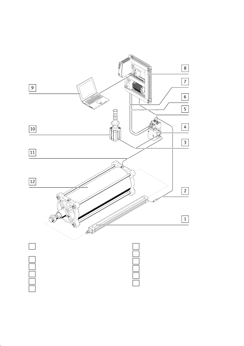
5 Product overview......................................................................................................... 7
5.1 Scope of delivery.......................................................................................................... 8
5.2 Function....................................................................................................................... 8
6 Transport..................................................................................................................... 8
7 Assembly..................................................................................................................... 9
8 Installation.................................................................................................................. 10
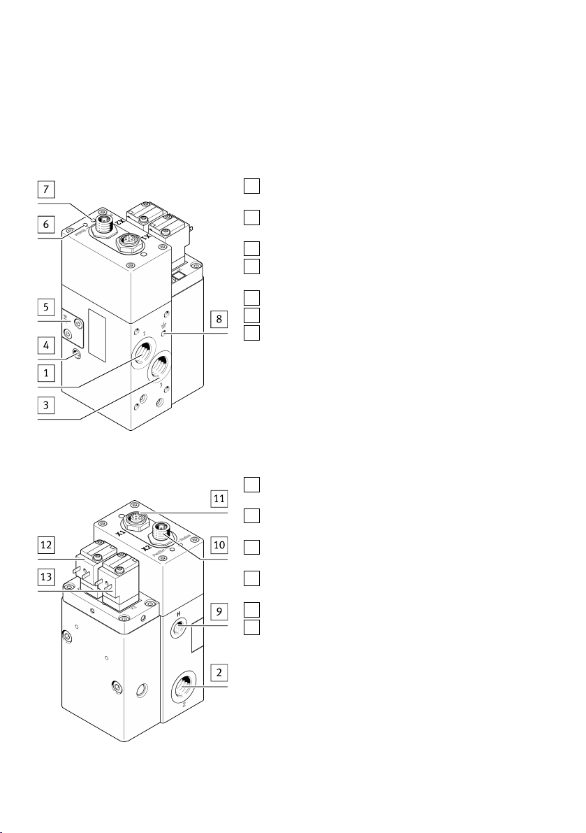
8.1 Valve unit interfaces..................................................................................................... 10
8.2 Pneumatic installation.................................................................................................. 11
8.3 Electrical installation.................................................................................................... 11
9 Commissioning............................................................................................................ 14
10 Operation..................................................................................................................... 14
11 Maintenance................................................................................................................ 15
11.1 Cleaning....................................................................................................................... 15
12 Malfunctions............................................................................................................... 15
12.1 Repair............................................................................................................................15
13 Disassembly................................................................................................................ 15
14 Disposal........................................................................................................................16
15 Technical data............................................................................................................. 16
Table of contents

1 About this document
This document only contains information on the assembly and installation of the enclosed individual
components. Application examples, information on implementing safety functions, commissioning and
operation are provided in separate documents.
1.1 Applicable documents
All available documents for the product èwww.festo.com/sp.
Documents Product, type Table of contents
Operating instruc-
tions
Control system CMCB-D1-C-S0 Assembly, installation
Catalogue inform-
ation
Standards-based cylinder,
DSBG-...
Technical data
Instruction manu-
al
Standards-based cylinder with dis-
placement encoder
DNCI-32-...
Operation
Instruction manu-
al
Control element,
VAOH-P15-H13
Operation
Instruction manu-
al
Valve unit,
VPCB-...-T22
Operation, installation
Instruction manu-
al
Connector-SET
VABS-P15-S-B6
Assembly
Description Controller,
CECC-D-…
Operation
Brief description Controller,
CECC-D-…
Installation
Circuit diagram Balancer kit,
YHBP
Electrical and pneumatic interconnec-
tion
Instruction manu-
al
Connecting cable,
NEBC-M12G5-KS-LE5-CO
Operation
Instruction manu-
al
Proximity switch,
SMT-8M-A-PS-24V-E-0.3-M8D
Operation
Catalogue inform-
ation
Connecting cable,
KME-1-24DC-5-LED
Technical data
Tab. 1 Further applicable documents on the balancer kit
About this document
Festo — YHBP — 2020-094

The range of application and certifications of the individual components of the kit are described in
separate documents èwww.festo.com/sp.
Download configuration-dependent documents
The technical data for the product are set out in configuration-dependent documents.
These documents form part of the product documentation and can be downloaded as follows.
1. Read the order ID/Product Key/Data Matrix Code of the product.
2. Download documents from the Festo Support Portal by entering the order ID/Product Key/Data
Matrix Code èwww.festo.com/sp.
3. Print out documents and keep together with this description.
Additional documents
In addition to the applicable documents, additional documents in the form of application notes are
available for download èwww.festo.com/sp.
Documents Product, type Table of contents
Application notes1) Balancer kit,
YHBP
– Commissioning
– Operation and special functions
– Implementation of safety functions
– …
1) Application notes are regularly revised and updated.
Tab. 2 Additional documents
2 Safety
2.1 General safety instructions
– Observe labelling on the product.
– Take into consideration the ambient conditions at the location of use.
– Prior to mounting, installation and maintenance work: Switch off power supply and secure it from
being switched back on.
– Prior to mounting, installation and maintenance work: Switch off compressed air supply and
secure it from being switched back on.
– Comply with the handling specifications for electrostatically sensitive devices.
– Observe tightening torques. Unless otherwise specified, the tolerance is±20%.
Safety
5Festo — YHBP — 2020-09

2.2 Intended use
This product is a kit for implementing the actuation, regulation and control function of a hand-guided
balancer.
Use the product only as follows:
– in perfect technical condition
– in its original condition, without unauthorised modifications
– within the limits of the product defined by the technical data
– in an industrial environment
– permanently mounted
2.3 Foreseeable misuse
Never use the product as follows:
– With unauthorised modifications or alterations to the product
– With load limits exceeded
– In an invalid mounting position
2.4 Training of qualified personnel
Installation, commissioning, maintenance and disassembly should only be conducted by qualified per-
sonnel.
The personnel must be familiar with the installation of mechatronic control systems.
3 Further information
– Accessories èwww.festo.com/catalogue.
– Spare parts èwww.festo.com/spareparts.
4 Service
Contact your regional Festo contact person if you have technical questions èwww.festo.com.
Further information
6 Festo — YHBP — 2020-09

5 Product overview
1Cylinder DNCI with displacement encoder
system and mounted proximity switch SMT
2Connecting cable of the DNCI
3Tubing (not in scope of delivery)
4Valve unit VPCB-...-T22
5[-WD3] connecting cable
6[-WD1] control of shut-off valve 1
7[-WD2] control of shut-off valve 2
8Mounting plate CMCB-D1-C-S0
9Laptop (not in scope of delivery)
10 Control element VAOH
11 Connecting tube (not in scope of delivery)
12 Working cylinder DSBG
Fig. 1 Product overview YHBP with mounting plate CMCB-D1-S0
Product overview
7Festo — YHBP — 2020-09

5.1 Scope of delivery
The kit only contains individual components that can be used for building a servo-pneumatic balancer.
Only the assembly and installation of these components is described. Not all components needed for
building a complete servo-pneumatic balancer are included. The manufacturer of the servo-pneumatic
balancer is responsible for implementing and observing all standards, guidelines and regulations.
Supporting application notes on various topics are provided è 1.1 Applicable documents.
5.2 Function
With this balancer kit, the safety functions "Safely limited speed" (SLS) and "Safe stopping and con-
trol" (SSC) can be implemented with pneumatic actuators in performance level b (PLb).
The controller for the balancer kit automatically detects the weight of the load and automatically
adjusts the balancing force. It is capable of detecting weight changes when floating.
Two operating modes can be realised:
– Load-controlled mode:
The load mass is moved with the control element VAOH or alternatively directly at the workpiece.
An adjustment of the mass does not take place in this operating mode.
Weight changes are not detected in this mode.
– Position-Halten Mode:
The load mass is only moved via the control element. The load is kept in each position, even if this
changes. Loads can be picked up or set down via the control element.
An exact description of the operating modes can be found in the application notes
è 1.1 Applicable documents.
6 Transport
Sequence of transport and unpackaging
NOTICE!
Damage to the product due to incorrect transport.
• Observe the transport labelling and information on the packaging.
1. Transport the product to the installation/storage location in its packaging and set it down on a
firm and flat base.
2. When storing: Pay attention to the storage conditions è 15 Technical data.
NOTICE!
Damage to the product due to incorrect unpacking.
• Observe the labelling and information on unpacking shown on the packaging.
• Unpack the product with at least 2 persons present.
• Use appropriate tools.
• Parts of the packaging are large and heavy:
– Do not let any parts fall onto the product.
– Use suitable aids to raise and lower the product (e.g. crane).
Transport
8 Festo — YHBP — 2020-09

3. Remove the packaging in accordance with the printed sequence.
7 Assembly
CAUTION!
Risk of injury due to falling product.
• Make sure the mounting surface is sufficiently strong to absorb the maximum forces.
• Only use suitable mounting components.
• Secure the screw connections.
Observe the information on mounting components in the applicable documentation
è 1.1 Applicable documents.
1. Assemble the cylinder DSBG and accessories as follows.
– Assemble the DSBG backlash-free and free from transverse loads.
– To prevent friction, ensure parallelism with the guide unit.
– If possible, use a self-aligning rod coupler to balance the angular and radial backlash.
2. Mount the proximity switch SMT as a reference sensor to the displacement encoder DNCI. The
proximity switch is needed for homing the displacement encoder. Information on homing
è 1.1 Applicable documents.
– Attach the proximity switch near the lower end position of the DNCI. Tightening torque:
£0.6Nm
3. Install the displacement encoder DNCI backlash-free and parallel to the cylinder DSBG.
– There must be a secure connection between the DSBG piston rod and DNCI piston rod.
– Choose suitable accessories in accordance with the installation situation.
4. Assemble the valve unit VPCB.
5. Connect the valve unit VPCB with the cylinder DSBG. There are two options for this:
– Connect the valve unit VPCB directly with the cylinder DSBG using a double nipple.
Internal diameter: ³8mm
–Connect the valve unit VPCB with a pipe or a suitable hydraulic hose £300mm with the cylin-
der DSBG.
A connection with the aid of tubing is not permitted.
6. Assemble the control element VAOH in the appropriate place. Tightening torque: £10Nm
Assembly
9Festo — YHBP — 2020-09

8 Installation
8.1 Valve unit interfaces
Interfaces VPCB-...-T22
1Port [1]
G3/8 compressed air
3Port [3]
G3/8 exhaust air
4Manual exhausting
5Installation option for connection set VABS-P15-S-B6
for direct pressure measurement on cylinder DSBG
6"Status" LED
7“Power/Error” LED
8Earth connection
Fig. 2 VPCB interfaces
2Port [2]
G3/8 working air (balancer cylinder)
9Port [H]
G1/8 pneumatic control element
10 Connection [X2]
CECC-D-BA (CAN interface)
11 Connection [X1]
DNCI displacement encoder
12 Shut-off valve 1
13 Shut-off valve 2
Fig. 3 VPCB interfaces
Installation
10 Festo — YHBP — 2020-09

8.2 Pneumatic installation
• Make pneumatic connections cable ends as short as possible.
• Ensure sufficient tightening torque for fittings and sealing the pneumatic connections. A leakage
can lead to unwanted system behaviour.
For details on pneumatic installation, see circuit diagram è 1.1 Applicable documents.
1. Connect input [1] of valve unit VPCB with a service unit and filter mesh 5µm (not in scope of deliv-
ery). Tubing diameter: ³12mm
2. Connect pressure gauge input [H] of valve unit VPCB with handle VAOH.
– Tubing diameter: 6mm
–Tube length: ³0.5m…£10m.
3. Assemble the silencer (not in scope of delivery) as follows:
– Mount the silencer on the exhaust port [3] of the valve unit VPCB.
– Mount the silencer on the exhausted cylinder chamber.
Ensure sufficient sizing of the silencer to prevent backpressure and increased noise emissions. In
the case of a ducted exhaust, connect the exhaust compressed air system instead of the silencer.
8.3 Electrical installation
WARNING!
Risk of injury due to electric shock.
• For the electric power supply, use only PELV circuits that ensure a reliable electric disconnection
from the mains network.
• Observe IEC60204-1/EN60204-1.
Not all required parts are included in the scope of delivery. For the complete installation, the actuating
elements for the following functions are needed at a minimum:
– Operation enable
– System enable
– Switch between the operating modes
– Reset fault
Details on the electrical installation are described in the enclosed circuit diagram and in the corres-
ponding application notes è 1.1 Applicable documents.
All pre-assembled cables are labelled with inscription labels [-WDx] in accordance with the circuit dia-
gram.
1. Connect the connecting cable of the displacement encoder of the DNCI to the corresponding input
of the valve block VPCB.
2. Push the plug sockets with cables [-WD1] and [-WD2] onto the corresponding shut-off valves of
the valve unit VPCB.
Installation
11Festo — YHBP — 2020-09

3. Screw the plug socket with cable together: tightening torque £0.35Nm.
4. Connect the CAN interface [X2] of the valve unit VPCB with cable [-WD3] to the CAN interface [X6]
of the balancer controller CECC-D-BA.
5. Establish connections to the digital inputs and outputs of the balancer controller CECC-D-BA
according to your application in accordance with the circuit diagram.
Pin allocation CAN connecting cable [-WD3]
VPCB-...-T22 Signal
Connection
[X2]
Pin
1 Shield
2 24VDC
3 0VDC
4 CAN_H
5 CAN_L
Tab. 3 Pin allocation CAN connecting cable [-WD3]
Earthing
– Connect the earth terminal of the valve block VPCB to the earth potential with low impedance
using an earthing cable, self-tapping screw and toothed disc (included in the scope of delivery).
– Connect the earth terminal of the sensor interface CASB-MT-D3-R7 with low impedance to the
earth potential.
Power supply of the digital I/Os
Observe the technical data of the balancer controller CECC-D-BA è 1.1 Applicable documents.
External components
The external control and display elements must be connected via the terminals of the mounting plate.
Installation
12 Festo — YHBP — 2020-09

Connection, reference sensor
Connect the proximity switch SMT-8M-A-PS-24V -...- M8D, which serves as a reference sensor, to the
control system with a connecting cable [-WD6].
SMT-8M-A-PS-24V-...-OE
Pin Signal
1 24VDC supply
3 Switching output
4 GND
Tab. 4 Connection, reference sensor
Ethernet interface
NOTICE!
Unauthorised Access to the Device Can Cause Damage or Malfunction.
• When connecting the device to a network, protect the network from unauthorised access.
Standards for security in information technology can be used for network protection meas-
ures,e.g. IEC62443, ISO/IEC27001.
The Ethernet interface of the balancer controller CECC-D-BA is a RJ-45 socket and is used for the con-
figuration and parameterisation of the system with a PC or tablet connected to the network.
After the mechanical and electrical installation, the servo-pneumatic balancer can be commissioned
with a web browser. The prerequisite is that the integrated controller CECC-D-BA is integrated in the
local network.
Access is through entry in the address line: http://<<IP address>>:8080/webvisu.htm
Example: http://192.168.2.20:8080/webvisu.htm
Minimum requirements for a PC/tablet
– Web browser with Java Script and support of HTML5 Canvas, e.g. Firefox, Chrome, Internet
Explorer ³ Version9
– Screen resolution 1280 x 768 pixels
Installation
13Festo — YHBP — 2020-09

9 Commissioning
CAUTION!
Risk of injury due to unexpected movement of components.
• Protect the positioning range from unwanted intervention.
• Keep foreign objects out of the positioning range.
• Perform commissioning at low speed.
NOTICE!
Material damage due to incorrect or incomplete installation.
The following conditions must be fulfilled for commissioning:
• The system must be fully assembled.
• The electrical installation must be complete and checked.
• The pneumatic installation must be complete and checked.
Prior to commissioning, a safety analysis must be carried out and all appropriate measures implemen-
ted. Commissioning is dependent on the customer-specific application.
– During commissioning, observe the associated documentation for the installed individual com-
ponents è 1.1 Applicable documents.
Web visualisation of the balancer controller CECC-D-BA enables commissioning via the web browser
è 1.1 Applicable documents.
Power supply
When switching on the power supply, proceed as follows:
1. Switch on the power supply.
2. Switch on the compressed air supply.
10 Operation
Operation is dependent on the customer-specific application.
Supplementary notes on operation è Additional documents.
During operation, observe the associated documentation for the individual components installed
è 1.1 Applicable documents.
Commissioning
14 Festo — YHBP — 2020-09

11 Maintenance
The rate of descent during operation of the manual exhausting is dependent on the customer-specific
application.
Before starting maintenance and cleaning work:
1. Slowly lower the balancer with the aid of manual exhausting at the valve unit VPCB into a safe
position or secure it from dropping with suitable measures.
2. Exhaust system parts with stored compressed air.
3. Switch off the operating voltage and secure it against being switched on again.
4. Carry out maintenance work on the various installed components in accordance with the relevant
documentation è 1.1 Applicable documents.
11.1 Cleaning
Clean the outside of the product with a soft cloth. Do not use aggressive cleaning agents.
12 Malfunctions
The display and elimination of malfunctions are dependent on the customer-specific application.
– During operation, observe the associated documentation for the individual components installed
è 1.1 Applicable documents.
12.1 Repair
In the event of repair, contact the Festo repair service èwww.festo.com.
13 Disassembly
The descent rate during operation of the manual exhausting is dependent on the customer-specific
application.
Before the commencement of disassembly work:
1. Slowly lower the balancer with the aid of manual exhausting on the valve unit VPCB into a safe
position or secure it from falling using suitable measures.
2. Exhaust system parts with stored compressed air.
3. Switch off the operating voltage and secure it against being switched on again.
4. During disassembly, observe the associated documentation for the individual components
installed è 1.1 Applicable documents.
Maintenance
15Festo — YHBP — 2020-09

14 Disposal
ENVIRONMENT!
Send the packaging and product for environmentally sound recycling in accordance with the current
regulations èwww.festo.com/sp.
15 Technical data
Identifier
Storage temperature [°C] –20…+70
Ambient temperature [°C] 0…50
Operating voltage DC [V] 21.6…26.4
Residual ripple [%] 5
Duty cycle [%] 100
Operating medium Compressed air in accordance with ISO 8573-1:2010 [6:4:4]
Lubricated operation not possible.
Maximum particle size 5µm.
Operating pressure [psi] 58…116
[bar] 4…8
Travel velocity [m/s] £1
achievable perform-
ance level
PLb for SLS/SSC
Product weight [kg] 4.8…60.5
Note on materials Contains PWIS
Transmission ratio of the kinematics
Lifting columns 1:1
Parallel kinematics 1:1…1:5
Degree of protection (in assembled state)
Kinematics system
CASB
VPCB
IP65
CMCB -...- C IP20
Tab. 5 General technical data
Disposal
16 Festo — YHBP — 2020-09

Identifier Cylinder diameter [mm]
50 63 80 100 125 160 200
Stroke
minimum [mm] 100
maximum [mm] 1990 1990 1990 1990 1990 1000 1000
Mass load1)
minimum [kg] 25 43 70 112 175 258 448
maximum [kg] 100 170 305 480 750 999 999
1) at 6 bar and a transmission ratio of 1: 1
Tab. 6 Size-dependent technical data
Technical data
17Festo — YHBP — 2020-09

© 2020 all rights reserved to Festo SE & Co. KG
Festo SE & Co. KG
73734 Esslingen
Ruiter Straße 82
Germany
+49 711 347-0
www.festo.com
Internet:
Phone:
Table of contents
Other Festo Wheel Balancer manuals
Popular Wheel Balancer manuals by other brands

Hofmann
Hofmann geodyna 4801P INSTRUCTIONS FOR ADJUSTMENT

Snap-On
Snap-On EEWB334A Operator's manual

Beissbarth
Beissbarth MT ZERO 6 LCD Translation of the original operating instructions

BRIGHT
BRIGHT CB460 Series manual

Snap-On
Snap-On EEWB330B Operator's manual

Snap-on Incorporated
Snap-on Incorporated EEWB314A Service manual