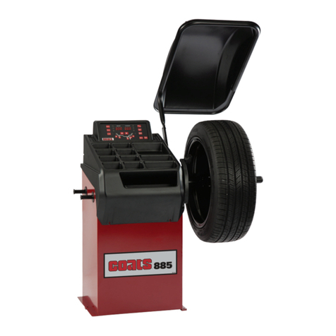
HENNESSY INDUSTRIES COATS 700 User manual

1601 J. P. Hennessy Drive, LaVergne, TN USA 37086-3565 615/641-7533 800/688-6359 Manual Part No.: 8111807 06
HENNESSY INDUSTRIES INC. Manufacturer of AMMCO®, COATS®and BADA®Automotive Service Equipment and Tools. Revision: 03/08
700 Solid State
WHEEL BALANCER
Installation Instructions
Operating Instructions
Safety Instructions
Maintenance Instructions
READ these instructions before placing unit in
service KEEP these and other materials delivered
with the unit in a binder near the machine for
ease of reference by supervisors and operators.

ii • COATS 700 Balancer

Table of Contents
Before You Begin
Receiving . . . . . . . . . . . . . . . . . . . . . . . . . . . .vi
Specifications . . . . . . . . . . . . . . . . . . . . . . . . .vi
Electrical Requirements . . . . . . . . . . . . . . . . .vi
Features . . . . . . . . . . . . . . . . . . . . . . . . . . . . .vi
Standard Accessories . . . . . . . . . . . . . . . . . . .vi
Optional Accessories . . . . . . . . . . . . . . . . . . .vi
Assembly and Setup
Floor and Space Requirements . . . . . . . . . . . .1
Unpacking the Unit . . . . . . . . . . . . . . . . . . . . .1
Remove Balancer from Pallet . . . . . . . . . . . . .1
Connecting to Power . . . . . . . . . . . . . . . . . . .1
Initial Testing . . . . . . . . . . . . . . . . . . . . . . . . . .1
Operating the Balancer
Wheel Mounting . . . . . . . . . . . . . . . . . . . . . . .2
Selecting Operating Options . . . . . . . . . . . . . .3
Entering Wheel Measurements . . . . . . . . . . .4
Balance the Wheel . . . . . . . . . . . . . . . . . . . . .4
Alloy Balancing . . . . . . . . . . . . . . . . . . . . . . . .5
Static Balancing . . . . . . . . . . . . . . . . . . . . . . . .5
Maintenance and Service
Preventative Maintenance . . . . . . . . . . . . . . .6
Service . . . . . . . . . . . . . . . . . . . . . . . . . . . . . .6
Calibration Check Procedure . . . . . . . . . . . . . .6
Calibration Procedure . . . . . . . . . . . . . . . . . . .6
Troubleshooting
Special Problems . . . . . . . . . . . . . . . . . . . . . . .7
Operator Complaints . . . . . . . . . . . . . . . . . . . .7
COATS 700 Balancer • iii

1. Read all instructions
2. Do not operate equipment with a damaged cord or if the equipment has been dropped or
damaged – until it has been examined by a qualified serviceman.
3. Do not let cord hang over edge of table, bench, or counter, or come in contact with hot manifolds
or moving fan blades.
4. If an extension cord is necessary, a cord with a current rating equal to or more than that of the
equipment should be used. Cords rated for less current than the equipment may overheat. Care
should be taken to arrange the cord so that it will not be tripped over or pulled.
5. Always unplug equipment from electrical outlet when not in use. Never use the cord to pull the
plug from the outlet. Grasp plug and pull to disconnect.
6. To reduce the risk of fire, do not operate equipment in the vicinity of open containers or
flammable liquids (gasoline).
7. Adequate ventilation should be provided when working on internal combustion engines.
8. Keep hair, loose clothing, fingers, and all body parts away from moving parts.
9. To reduce the risk of electrical shock, do not use on wet surfaces or expose to rain.
10. Use only as described in this manual. Use only manufacturer’s recommended attachments.
11. ALWAYS WEAR SAFETY GLASSES. Everyday glasses only have impact resistant lenses, they are
NOT safety glasses.
12. Do not disable the hood safety interlock system, or in any way shortcut safety controls and
operations.
13. Be sure wheels are mounted properly, the hub nut engages the arbor not less than 4 turns, and
the hub nut is firmly tightened before spinning the wheel.
14. Maintain all electrical cords in good repair. Do not operate damaged equipment until it has been
examined by a qualified service technician.
15. Be sure the balancer is properly connected to the power supply and electrically grounded.
16. Read and understand this manual before operating. Abuse and misuse will shorten functional life.
17. Keep guards and safety features in place and in working order.
18. Wear proper clothing. Safety toe, non-slip footwear and protective hair covering to contain hair
are recommended. Do not wear jewelry, loose clothing, neckties, or gloves when operating the
balancer.
19. Keep work area clean and well lighted. Cluttered and/or dark areas invite accidents.
20. Disconnect balancer before servicing.
21. Repair or replace any part that is damaged or worn and that may cause unsafe balancer
operation. Do not operate damaged equipment until it has been examined by a qualified service
technician.
22. Never overload or stand on the balancer.
23. Do not allow untrained persons to operate machinery.
iv • COATS 700 Balancer
IMPORTANT SAFETY INSTRUCTIONS
SAVE THESE INSTRUCTIONS

Definitions of Hazard Levels
Identify the hazard levels used in this manual with the
following definitions and signal words:
DANGER
Watch for this symbol:
It Means: Immediate hazards which will result in
severe personal injury or death.
WARNING
Watch for this symbol:
It Means: Hazards or unsafe practices which could
result in severe personal injury or death.
CAUTION
Watch for this symbol:
It Means: Hazards or unsafe practices which could
result in minor personal injury or product or property
damage.
Watch for this symbol. It means BE ALERT!
Your safety, or the safety of others, is
involved.
Owner’s Responsibility
To maintain machine and user safety, the
responsibility of the owner is to read and follow these
instructions:
• Follow all installation instructions and make sure
installation conforms to all applicable Local, State,
and Federal Codes, Rules, and Regulations; such as
State and Federal OSHA Regulations and Electrical
Codes.
• Carefully check the unit for correct initial function.
• Read and follow the safety instructions. Keep them
readily available for machine operators.
• Make certain all operators are properly trained,
know how to safely and correctly operate the unit,
and are properly supervised.
• Allow unit operation only with all parts in place and
operating safely.
• Carefully inspect the unit on a regular basis and
perform all maintenance as required.
• Service and maintain the unit only with authorized
or approved replacement parts.
• Keep all instructions permanently with the unit and
all decals/labels/notices on the unit clean and
visible.
COATS 700 Balancer • v
Failure to follow danger,
warning and caution
instructions may lead to
serious personal injury to operator or bystander,
or damage to property. Do not operate this
machine until you read and understand all the
dangers, warnings and cautions in this manual.
For additional copies of either, or further
information, contact:
Hennessy Industries
1601 J.P. Hennessy Drive
LaVergne, TN 37086-3565
615/641-7533 or 800/688-6359
www.ammcoats.com
WARNING
DANGER
WARNING
CAUTION

Before You Begin
Receiving
The shipment should be thoroughly inspected as
soon as it is received. The signed bill of lading is
acknowledgement, by the carrier, of receipt in good
condition of the shipment covered by our invoice.
If any of the goods called for on this bill of lading are
shorted or damaged, do not accept them until the
carrier makes a notation of the shorted or damaged
goods on the freight bill. Do this for your own
protection.
NOTIFY THE CARRIER AT ONCE if any hidden loss or
damage is discovered after receipt and request him
to make an inspection. If the carrier will not do so,
prepare an affidavit to the effect that you have so
notified the carrier (on a certain date) and that he has
failed to comply with your request.
IT IS DIFFICULT TO COLLECT FOR LOSS OR
DAMAGE AFTER YOU HAVE GIVEN THE CARRIER A
CLEAR RECEIPT.
File your claim with the carrier promptly. Support your
claim with copies of the bill of lading, freight bill,
invoice, and photographs, if possible.
Although COATS responsibility ceases upon delivery
of the shipment to the carrier, we will gladly assist in
tracing lost shipments. Our willingness to assist in
every possible manner does not make Coats
responsible for collection of claims, or replacement of
lost or damaged materials.
Specifications
• Cycle time 10 seconds (avg.)
• Tire/Wheel Weight 56 pounds max.
• Wheel Diameter Range 4 to 34.0 inches
• Wheel Width Range 2 to 18.6 inches
• Maximum Duty Cycle 40 wheels/hr @ 56 lbs.
• Balancing Increments
Normal Mode 0.25-ounce (7 grams)
Fine Balance Mode 0.01-ounce (2.8 grams)
(5-gram increments from 5 to 50 grams 10-gram
increments from 50 to 100)
• Motor
Modified torque with 850 RPM rating, large
housing for heat dissipation, and heavy duty
insulation for high temperature applications.
• Shipping Weight 260 pounds
Electrical Requirements
The balancer requires a 110 VAC, 50/60Hz, single-
phase power supply with 15 amp fuse or circuit
breaker and properly grounded three-pin safety
outlet.
Features
• Exclusive Direct Drive System - No Pulleys or Belts
• Balances Most Automotive Wheels
• Single-Spin Dynamic Two-Plane or Static Balancing
• Vertical Wheel Mounting
• Back Cone and Front Cone Mounting
• “No Bolt-Down” Installation
• Scratch Resistant Control Panel
• Easy-to-Read LEDs and Displays
• Automatic Calibration
• Removable Shaft Stud
• Automatic Rim Gauge Return
• Dynamic, Static, and Alloy Operating Modes
• Solid State Motor Controller
Standard Accessories
• Built-in Weight Tray
• 3 Back Cones
• Threaded Stud
• Back Cone Spring
• Hub Nut
• Pressure Drum
• Rim Width Calipers
Optional Accessories
• Combi Adapter for Special Wheels (P/N 8309060)
• Wheel Weight Pliers (P/N 8111515)
• Hood Kit (P/N 8110935) - only applies to non-UL
certified 700 balancer purchased without hood.
• Hub Centric Truck Mounting System (P/N 8113041C)
• Pin Plate Kit Mounting System (P/N 8113091C)
• Balancer Chuck Mounting System (P/N 8113326C)
• 40MM Conversion Shaft/Cone Kit (P/N 8113307)
• Light Truck Cone Mounting System (P/N 8113276C)
vi • COATS 700 Balancer

Assembly and Setup
Floor and Space Requirements
Floor must be solid and flat concrete. The balancer
does not need to be bolted to the floor in normal
service. The balancer may be bolted to the floor with
anchor bolts through the three support feet, but will
require an alternate electrical connection method.
Whether free standing or bolted to the floor, the
balancer must stand only on the three support feet
attached to the unit.
Sufficient space must be provided above and around
the balancer for mounting and demounting wheels.
Figure 1a - Space Requirements With Hood
Figure 1b - Space Requirements Without Hood
Unpacking the Unit
1. Remove the shipping carton from the pallet.
2. Remove all loose parts and accessories packed
around the unit.
Remove Balancer from Pallet
3. Remove the shipping bolts that hold the balancer
to the pallet.
Do not use the control pod, control pod arm,
faceplate, hood or stub
shaft to lift the balancer.
Use help to remove the
balancer from the pallet.
The unit is heavy and the
weight is not evenly distributed. Dropping the
unit may cause personal injury or equipment
damage.
4. Lift the balancer off the pallet and place it in its
operating location.
5. Install and tighten the threaded stud into the end
of the motor shaft.
Connecting to Power
Consult a licensed electrical contractor for proper
connection that meets local electrical codes. Power
outlets must be located in a floor raceway or
overhead drop if pedestrians or equipment traffic
pose a threat of damage to the power cord.
The balancer requires a nominal 115 VAC, 60 Hz,
single-phase power supply with a 15 amp fuse or
circuit breaker and a three-pin safety outlet.
Electrical outlets must have a solid connection of less
than 1 ohm between the ground pin and building
ground.
Operation with a defective
ground circuit will create a
shock hazard for the
operator, damage the unit electronics, and will
void the warranty.
Power and ground requirements must be verified by
the installer or an inspector before connecting the
balancer. Failure to observe this precaution may void
the warranty.
If the balancer is bolted to the floor, a licensed
electrical contractor must be consulted. Most
electrical codes require “hard” wiring when the
balancer is bolted down.
Figure 2 - Electrical Outlet Requirements
Initial Testing
1. Plug the unit into an appropriate power outlet. If
the circuit breaker for the outlet is off, turn it on.
2. Turn the balancer on. The power switch is on the
back of the unit.
COATS 700 Balancer • 1
WARNING
CAUTION
CAUTION
Single-Phase
115 VAC
115 V
between A &
B
A - White B - Black
Ground - Green
48 inches 56 inches
76 inches
41 inches 41 inches
70 inches

Operating the Balancer
Wheel Mounting
Mount the wheel using the most appropriate
mounting method.
A. Back Cone Mounting—Almost all wheels,
including aftermarket or mag wheels, can be
mounted using one of the back cones. The spring
must be used.
Figure 3 - Back Cone Mounting
1. Place the spring over the threaded stud with the
large end inside the faceplate.
2. Determine which cone best fits the wheel
center hole. Slide the cone onto the shaft with
the large end against the spring.
3. Lift the wheel onto the cone with the inside of
the wheel facing the balancer. Center the wheel
on the cone.
4. For most wheels, the pressure cup should be
snapped onto the hub nut. A nylon spacer (“no
mar” ring) can also be used to protect custom
wheel finishes.
5. Thread the hub nut onto the shaft, and tighten it
against the wheel. The wheel must be forced
firmly against the faceplate. The hub nut must
engage the threads for at least three full turns.
NOTE: If the hub nut will not tighten completely,
use the front cone mounting method.
Failure to tighten the hub
nut properly may result in
the wheel dismounting,
causing personal injury and property damage.
B. Front Cone Mounting—Used when the wheel
cannot be securely mounted using the back cone
method.
Figure 4 - Front Cone Mounting
1. Determine which cone best fits the wheel
center hole.
2. Lift the wheel onto the shaft and push it back
against the faceplate.
3. Slide the cone onto the shaft. Lift the wheel and
center it on the cone.
4. Thread the hubnut onto the shaft and tighten it
against the cone. The hubnut must engage the
threads for at least three full turns.
NOTE: If the hub nut will not tighten completely
because of a lack of threads, use an additional
cone as a spacer between the mounting cone
and the hubnut. The wheel must be forced firmly
against the faceplate.
Failure to tighten the hub
nut properly may result in
the wheel dismounting,
causing personal injury and property damage.
2• COATS 700 Balancer
WARNING
WARNING
Rim
Rim
Spring
Cone
Cone
Pressure Cup
Hub Nut
Hub Nut

C. Optional Combi Adapter—Can be used for 3, 4,
5, 6, 8, or 10 lug wheels by installing the appropriate
number of swivel plates.
Figure 5 - Combi Adapter (optional)
1. Install a swivel plate over the adapter plate hole
marked 3 4 5 and secure with a shoulder bolt.
Align the mark on the plate with the dot on the
number gear. Do not tighten the bolt.
2. Install swivel plates next to the appropriate
numbers (next to the 3’s for 3 and 6 lug wheels,
the 4’s for 4 and 8 lug wheels, and the 5’s for 5
and 10 lug wheels). Align the marks on the
plates with the dots on the number gear. Secure
with a shoulder bolt, but do not tighten.
3. Attach the adapter to the wheel. Rotate the
swivel plates until the lugs align with the holes in
the wheel.
4. Install the lug nuts and tighten with the adapter
wrench. Use a crossing (star) pattern to tighten
the lug nuts. Reverse the lug nuts as necessary
for proper fit in the lug hole on the wheel.
5. Tighten the swivel plate shoulder bolts with the
allen wrench.
6. Align the bolts on the back of the adapter with
the holes in the faceplate. Thread a faceplate nut
onto each bolt. Hand tighten the nuts while
rotating the wheel to ensure proper centering.
The lug nuts must be
centered and threaded at
least four full turns.
Reverse the lug nuts as required for best fit. Use
only the adapter wrench furnished. Do not use air
tools or impact wrenches.
D. Optional Light Truck Cone—Allows secure
mounting of most light truck wheels.
1. Lift wheel onto threaded shaft. Push it back
against the faceplate.
2. Slide cone onto shaft, and center in wheel
center hole. The cone lip will help hold the wheel
while tightening the hub nut.
Figure 6 - Light Truck Cone (optional)
3. Thread the hub nut onto the shaft and tighten
against the cone completely. The wheel must be
forced firmly against the faceplate. The hub nut
must engage the threads for at least three full
turns.
Failure to tighten the hub
nut properly may result in
the wheel dismounting,
causing personal injury and property damage.
Selecting Operating Options
Gram/Ounce Toggles unit between weight
readings in ounces or grams. Press
and hold SHIFT and press
GRAM/OUNCE
Round Off Toggles unit between normal mode
(0.25-ounce increments) and fine
balance mode (0.01-ounce/1-gram
increments). Normal mode is 5-gram
increments from 0 to 50, and 10-gram
increments from 50 to 100. Press and
hold SHIFT and press ROUNDOFF.
Calibrate Places unit in the calibration mode.
Press and hold SHIFT and press
CALIBRATE.
Mode Selects the balancing mode. Press
MODE until the LED above the
desired mode is illuminated.
COATS 700 Balancer • 3
WARNING
WARNING
Faceplate
Light Truck
Cone
Hub Nut
Swivel Plate
Swivel Plate
Bolt
Washer
(optional)
Faceplate
Nut
Number
Gear
Center
Bushing
Alignment
Mark
Combi Plate
Alignment

Entering Wheel Measurements
Wheel measurement data is entered using the wheel
measurement keys on the control panel. The top key
is for wheel offset (the distance between the edge of
the wheel and the balancer, Figure 7). The center key
is for rim width (Figure 8). The bottom key is for rim
diameter (this measurement is found on the sidewall
of the tire).
1. Pull the offset handle out from the upper right
side of the balancer and over to the wheel.
Rotate the handle until the end touches the
second surface of the rim flange.
Figure 7 - Measuring Wheel Offset
2. Read the last legible number on the offset handle
and enter this number by pressing the offset key
then the appropriate numbers on the keypad (for
example, press 6 then 5 to enter a measurement
of 6.5 inches).
3. Press the diameter key and use the keypad to
enter the wheel diameter shown on the tire
sidewall.
4. Fit the calipers over the top of the wheel. Touch
the ends of the caliper arms to the outside of the
rim. On standard wheels, the calipers should
touch the vertical rim surface (not the rolled rim
flange). On mag wheels, the calipers should
touch the flat rim edge.
Figure 8 - Measuring Wheel Width with Calipers
5. Read the measurement on the calipers and enter
it by pressing the width key and the appropriate
numbers on the keypad (for example, press 8
then 5 to enter a wheel width of 8.5 inches)
Balance the Wheel
REMEMBER: This balancer may or may not have a
hood to cover the spinning wheel. Non-UL certified
balancers come without a hood. A non-hooded
balancer can be cycled by pressing the start button.
Exercise caution when using the balancer. Wear eye
protection. Keep bystanders away from operating
balancer. Do not attempt to stop the wheel manually -
wait for the balancer to brake the wheel to a complete
stop before coming in contact with the wheel.
1. Remove any weights from the wheel. Lower
hood, press START. The balancer will spin and
stop automatically.
To use the fine balance mode (0.01-ounce
increments) press and hold SHIFT and press
ROUND OFF.
2. Wait for the wheel to stop completely.
As the wheel brakes to a stop, weight
measurements will appear in the weight displays on
the control panel. The left display is for the left plane
of the wheel, and the right is for the right plane.
Next to each weight display is the weight
positioning lights. The two LEDs in the middle of
the positioning lights will blink alternately to
indicate proper weight position. The LEDs above
and below will indicate which way to rotate the
wheel to reach the weight position.
Figure 9 - Weight Positioning
3. Raise the hood and rotate the wheel until the left
weight position LEDs blink. Attach the specified
weight size at top dead center.
4. Rotate the wheel until the right weight position
LEDs blink. Attach the specified weight size at
top dead center.
NOTE: The more accurate you are in selecting
the exact weight and position; the more often
you will balance in one spin.
5. Lower the hood, press start, and respin the
wheel. Your weight readings should now be 0.00
(in normal mode).
6. Raise the hood and remove the wheel. If you are
balancing another wheel identical to this first one,
4• COATS 700 Balancer
Rim
Rim
Tire
Tire
Calipers
Calipers
Mag Wheel
Standard Wheel
Touch Second
Surface of Rim
Offset Measurement
Last Legible Number
Offset
Width
Left Weight
Weight Position LEDs
Weight Displays
Right
Top Dead Center

you do not need to remeasure the wheel or reset
the wheel measurements. Mount the tire, remove
any weights, lower the hood, and press START.
Alloy Balancing
Specialty wheels, balanced with adhesive backed
weights hidden on the inner surface of the wheel,
should be balanced in the ALLOY mode. When the
ALLOY mode is selected, the computer automatically
calculates the outer weight position as the middle of
the rim width. The inner weight position is under the
inner flange of the wheel (Figure 10). All alloy wheel
dimensions are measured and entered into the
balancer in the same manner as described in the
Entering Wheel Measurements section.
Weights must be attached
securely to wheel surfaces
cleaned according to weight
manufacturer’s recommendation. Failure to do so
may cause weight to come loose during a spin,
resulting in personal injury.
Two Adhesive Weights, Outside Weight Visible
1. Mount wheel and remove weights.
2. Press Mode key until the ALLOY LED is
illuminated.
3. Enter wheel offset, diameter, and rim width
measurements.
4. Lower the hood and press START. Wait for
readings to appear and wheel to stop.
5. Raise the hood and rotate wheel until left weight
position lights blink.
Figure 10 - Two Adhesive Weights, Right Weight Visible
6. Attach the specified weight to the left plane of
the wheel.
7. Rotate wheel until the right weight position lights
blink.
8. Attach the specified weight to the right plane of
the wheel.
9. Lower hood, press start, and respin the wheel.
Repeat Steps 5 through 8 until readings are 0.00.
NOTE: It is recommended that adhesive weights are
covered with aluminum foil or duct tape to keep the
weight clean and securely attached to the wheel.
IMPORTANT: After placing the balanced wheel on the
vehicle, check for adequate clearance between the
weight and the brake caliper.
Static Balancing
Static balanced wheels may wobble if the imbalance
mass is large enough and off the centerline of the rim
width. Wobble caused by an off center imbalance can
be corrected only by dynamic balancing of the wheel.
When the STATIC mode is selected, the computer
automatically calculates the middle of the rim width as
the proper weight position (Figure 11).
All wheel dimensions are measured and entered into
the balancer in the same manner as described in the
Entering Wheel Measurements section.
1. Press Mode key until the STATIC LED is
illuminated.
2. Lower hood and press START. Wait for the
reading to appear and the wheel to stop. The
weight displayed is the weight required to balance
the wheel (within 0.25-ounce).
3. Raise the hood and rotate the wheel until the
weight position lights blink.
4. Attach the specified weight to the center of the
wheel.
Figure 11 - Static Balance Weight Position
NOTE: It is recommended that adhesive weights are
covered with aluminum foil or duct tape to keep the
weight clean and securely attached to the wheel.
IMPORTANT: After placing the balanced wheel on the
vehicle, check for adequate clearance between the
weight and the brake caliper.
NOTE: If using static balancing mode with clip-on
weights, add 1.5-inches to the rim diameter to
compensate for weight placement.
COATS 700 Balancer • 5
CAUTION
Inner Weight
Outer Weight
Weight
Brake Caliper
Brake Caliper

Maintenance and Service
Do not use solvents, which
leave an oily residue.
Never use compressed air
or a water hose to clean
any part of your balancer.
Preventative Maintenance
Daily Clean shaft and faceplate with a vaporizing
solvent. Cones, hub nut, and other
mounting hardware should be checked and
cleaned.
Weekly Thoroughly clean entire unit. Remove all
used weights, tools, and parts from under
and around balancer. Perform a calibration
check. Make calibration adjustments if
required.
ATTENTION: Maximum duty cycle is 40 wheels per
hours at 56 pounds.
NOTE: Before each balancing operation, make sure
that the back face of the wheel is clean. Use a wire
brush to clean the back face of the wheel if needed.
Service
If service should ever be required for your balancer,
contact the Service Department at (800) 688-6359.
Have your model and serial number ready.
Calibration Check Procedure
This procedure can be performed by the operator to
ensure the balancer is operating correctly and
properly calibrated. The only purpose of calibration is
to fine-tune the balancer to yield single-spin
balancing.
Use the fine balance mode during this procedure
(press and hold SHIFT and press ROUND OFF).
If the balancer fails to produce the results outlined in
this procedure, perform a calibration adjustment.
1. Use normal mounting procedures to mount a
standard domestic 14, 15, or 16-inch diameter x
6 to 6-1/2-inch wide steel wheel with standard
tire mounted and properly inflated. Do not use a
wheel that is bent or misaligned. The center hole
must be free of nicks or burrs.
2. Enter the offset, rim width, and wheel diameter
measurements into the balancer.
3. Lower the hood and spin the wheel. Remember
to use the fine balance mode. Proceed to Step 4
when your weight displays read 0.10 ounces or
less (you may need to trim weights to
accomplish this).
4. Raise the hood and attach a 4-ounce test weight
to the right side of the rim.
5. Lower the hood and spin the wheel. The reading
in the right weight display should be between
3.85 and 4.15.
6. Raise the hood and rotate the wheel until the
outer weight positioning lights flash. The test
weight should be in the 6 o’clock position. The
inner weight reading should be 0.15 ounces or
less (this figure is the result of the interference
between the two balancing planes).
7. Repeat Steps 4, 5, and 6 with the test weight on
the left side of the rim.
Calibration Procedure
1. Mount a wheel that best represents the
tire/wheel size most commonly balanced on this
unit. In most cases, this will be a 14, 15, or 16-
inch diameter by 6 to 6-1/2-inch wide wheel.
Remember to remove any weights attached to
the wheel.
2. Enter the A (offset), W (width), and D (diameter)
measurements.
NOTE: It is important that you are accurate in
entering these measurements. Inaccurate
measurements will adversely affect your
calibration.
3. Press and hold SHIFT and press CALIBRATE.
“CAL 0” will appear in the displays to indicate
Calibration Mode.
4. Lower the hood and press START to spin the
wheel. Wait for the wheel to brake to a stop
before raising the hood.
5. The balancer will indicate a 4-ounce weight in
ounce mode (100 grams in grams mode). Rotate
the wheel until the right weight positioning lights
blink. Attach the weight at top dead center on
the right plane.
REMEMBER: The more accurate you are in
locating the weight on the wheel, the more
accurate your calibration.
6. Lower the hood and press START to respin the
wheel. When the wheel brakes to a stop,
calibration is complete and the balancer will
automatically exit the Calibration Mode.
6• COATS 700 Balancer
CAUTION
CAUTION

Troubleshooting
Special Problems
Customers will occasionally complain of vibration on
the car after balancing. Some possible causes are:
1. Beads are improperly seated. Check bead
seating and inflation pressure before balancing.
2. Stiffness variations in radial belts.
3. Tire or wheel out of round, wheel bent, or not
running true. Visually check runout of wheel and
tire during balance spin. Re-check mounting.
Replace wheel or tire as necessary.
4. Suspension wear, misalignment, or loose vehicle
components.
5. Wheels not correctly centered because of
damaged hub, damaged or worn center hole,
worn bolt circle holes, or imprecise original
design. Check wheel runout before balance spin
and again on the vehicle after re-mounting.
6. Sensitive suspension. Use the fine balance
mode.
Operator Complaints
1. Balancer uses too many weights or several spins
to balance.
Remedy: Re-check rim dimensions and correct
balancer settings as necessary.
Remedy: Position weights at exactly top dead
center when weight positioning lights flash.
Remedy: Calibrate balancer.
2. Weight or position readings fluctuate.
Remedy: Check cone and hub nut for slippage.
Tighten as needed.
Remedy: Verify that the balancer is sitting solidly
on its three mounting feet. Verify that the floor is
flat and stable, that there are no tools or weights
caught between the balancer and the floor.
COATS 700 Balancer • 7

8• COATS 700 Balancer
Notes

COATS 700 Balancer • 9
Notes

8111807 06 03/08 © Copyright 1999, 2002 Hennessy Industries and COATS All Rights Reserved Printed in USA
Table of contents
Other HENNESSY INDUSTRIES Wheel Balancer manuals

HENNESSY INDUSTRIES
HENNESSY INDUSTRIES Coats 1185 User manual

HENNESSY INDUSTRIES
HENNESSY INDUSTRIES Coats IBS 2000 User manual

HENNESSY INDUSTRIES
HENNESSY INDUSTRIES Coats 1100 User manual

HENNESSY INDUSTRIES
HENNESSY INDUSTRIES COATS 950 User manual

HENNESSY INDUSTRIES
HENNESSY INDUSTRIES Coats XR 1850 Series User manual

HENNESSY INDUSTRIES
HENNESSY INDUSTRIES coats 525 User manual

HENNESSY INDUSTRIES
HENNESSY INDUSTRIES coats ProRide Diagnostic User manual

HENNESSY INDUSTRIES
HENNESSY INDUSTRIES coats 1300-2D User manual

HENNESSY INDUSTRIES
HENNESSY INDUSTRIES coats 1000 User manual

HENNESSY INDUSTRIES
HENNESSY INDUSTRIES Coats Vero Series User manual