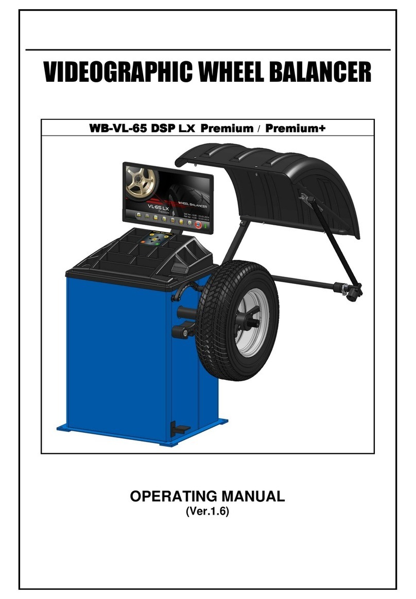
MANATEC LX WB-VL-65 DSP User manual

WHEEL BALANCER
WB-VL-65 DSP LX
WB-VL-65 DSP LX Premium
WB-VL-65 DSP LX Premium+
WB-VH-200 R
SERVICE MANUAL
(Ver.1.3)

INDEX Page No.
1. WARRANTY –STATUTORY CLAUSE 1
2. INSTALLATION 2
2.1. SAFETY INFORMATION 2
2.2. INSTALLATION REQUIREMENTS 2
2.2.1. LOCATION 2
2.2.2. POWER REQUIREMENT 2
2.2.3. SPACE REQUIREMENTS 3
2.2.4. ACCESSORIES & TOOLS REQUIREMENTS 3
2.3. UNPACKING 4
2.3.1. LCV MODELS 4
2.3.2. HCV MODELS 5
2.4. FOUNDATION 6
2.5. INTEGRATION 6
2.5.1. DISPLAY UNIT (Monitor column & Monitor) 6
2.5.2. WHEEL GUARD 7
2.5.3. WIDTH MEASURING ROD (Applicable only for Premium model) 8
2.5.4. MCD 8
3. DESCRIPTION OF MAIN PARTS 9
3.1. DSP BOARD WITH MINI UPS 9
3.2. POWER PANEL 9
3.2.1. MOTOR CONTROL BOARD 9
3.2.2. MOTOR CONTROL BOARD CUM EMI FILTER BOARD (for Rev.50 and above) 9
3.2.3. SBC BOARD 10
3.2.4. SMPS 11
3.2.5. EMI FILTER MODULE (for HCV model only) 11
3.3. ROTOR 11
3.3.1. MOTOR 11
3.3.2. PIEZO SENSOR 11
3.3.3. REVOLUTION INDEX ENCODER BOARD 12
3.3.4. MID CENTERING DEVICE (MCD) 12
3.4. MECHANICAL BRAKE 12
3.5. DISPLAY UNIT 12
3.6. KEYBOARD 13
3.7. DISTANCE / DIAMETER / WIDTH MEASUREMENT MECHANISM 13
3.7.1. E-DISTANCE ENCODER BOARD (For Wheel rim Distance measurement) 13
3.7.2. RLS SENSOR BOARD (For Wheel rim Inner, Outer Dia & Width measurement) 13
3.8. WHEEL GUARD 14
3.9. LASER / TORCH (Applicable for Premium + model only) 14
3.10. STICKER WEIGHT HOLDER (Applicable for Premium/+ model only) 14
4. OPTIONS 15
4.1. WEIGHT CALIBRATION 15
4.1.1. LCV MODELS 15
4.1.2. HCV MODELS 19
4.2. DIAMETER CALIBRATION (Applicable only for Premium/+ model) 22
4.3. WIDTH CALIBRATION (Applicable only for Premium model) 23
4.4. WHEEL TRACKING TEST 25
4.5. DISTANCE ROD TEST 26
4.6. SELF TEST 26
4.7. SENSOR TEST 26
4.8. LASER & TORCH SETTING (Applicable for Premuim+ model) 27
4.9. DUTY CYCLE TEST 27
4.10. KEYPAD TEST 27
4.11. BACKUP FACTORY DATA 28
4.12. CUSTOMER INFORMATION 28
4.13. RESET JOB NUMBER 28
4.14. RESTORE FACTORY CALIBRATION 29
4.15. WEIGHT CUTOFF 29

5. PARTS REPLACEMENT PROCEDURE 30
5.1. POWER PANEL 30
5.1.1. DSP BOARD 30
5.1.2. MOTOR CONTROL BOARD 30
5.1.3. SBC BOARD 31
5.1.4. MEMORY CARD (with Balancing program) 31
5.1.5. SMPS 32
5.1.6. MCB (HCV) 32
5.1.7. BUZZER 32
5.1.8. COOLING FAN 33
5.2. ROTOR 33
LCV MODELS 33
HCV MODELS 35
5.2.1. MOTOR 37
5.2.2. REVOLUTION INDEX ENCODER BOARD 37
5.2.3. PIEZO ELECTRIC SENSOR 38
5.3. MECHANICAL BRAKE (NA for SR Rev.R50/above & HCV models) 39
5.3.1. LIMIT SWITCH 39
5.3.2. MANUAL BRAKE 39
5.4. DISPLAY UNIT 40
5.5. DISTANCE / DIAMETER / WIDTH MEASUREMENT MECHANISM 40
5.5.1. DISTANCE MEASURING ROD 40
5.5.2. E-DISTANCE ENCODER BOARD (For Wheel rim Distance measurement) 40
5.5.3. RLS SENSOR BOARD (For Wheel rim Dia & Width/ Outer dia measurement) 41
5.6. WHEEL GUARD 42
5.6.1. LIMIT SWITCH 42
5.7. TORCH LIGHT 42
5.8. LASER BEAM 43
5.9. STICKER WEIGHT HOLDER 43
6. RECOMMENDED SPARE PARTS (For 2 years operation) 44
7. DIAGRAMS 45
7.1. BLOCK DIAGRAM 45
7.1.1. LCV MODELS 45
7.1.2. HCV MODEL 46
7.2. WIRING DIAGRAM 48
7.2.1. LCV MODELS 48
7.2.2. HCV MODEL 51
8. TROUBLE SHOOTING 54

Ref.: WB-VL-SM Ver.1 3.doc 1
1. WARRANTY –STATUTORY CLAUSE
The equipment is provided with Warranty for one year from the date of installation or thirteen
months from the date of despatch whichever is earlier, against any manufacturing defect. The
Warranty is subjected to the following conditions:
1. Ensure that proper power supply with protective Earthing is provided to the equipment
through uninterruptible Power Supply (UPS). Any high voltage may damage the
components, leading to system failure or electrical hazards.
Power supply:
For 230V 50/60Hz operation (LCV) : Single Phase, 230VAC ±10%, 50/60Hz +N +PE
For 110V 60/50Hz operation (LCV) : Single Phase, 110VAC ±10%, 60/50Hz +N +PE
For 415V 50/60Hz operation (HCV) : Three Phase, 400VAC ±5%, 50/60Hz +N +PE
For 220V 60/50Hz operation (HCV) : Three Phase, 220VAC ±5%, 60/50Hz +N +PE
For 415V 50/60Hz operation (HCV) : Three Phase, 400VAC ±5%, 50/60Hz +PE
For 220V 60/50Hz operation (HCV) : Three Phase, 220VAC ±5%, 60/50Hz +PE
For 220V 60/50Hz operation (HCV) : Single Phase, 220VAC ±5%, 60/50Hz +N +PE
Warranty ceases if this condition is not satisfied
2. Power supply to the equipment should be connected only through a CVT (1KVA capacity
for LCV models, 3KVA for HCV models) to avoid any failure of electronic parts due to
instantaneous high voltage. PLEASE AVOID CONNECTING WHEEL BALANCER
DIRECTLY TO MAINS.
3. Ensure that any heavy electrical equipments like Compressor / Welding machines / Car
washers / Medical equipments etc., are not connected to same power line.
4. All regulations in force concerning the safety at work must be complied when choosing the
installation location. In particular, the equipment must be installed and operated in
protected environments where there is no risk of dripping (or) direct sunlight.
5. Ensure that any equipment which produces Ultra Violet rays are not available in the same
premises.
6. The operating location must be free from heavy magnetic field.
7. Do not attempt to open or service the equipment under any circumstances.
Warranty ceases if the equipment is opened or serviced by un-authorised
personnel
8. While handling the PCBs, make sure to wear ESD wrist band.
9. Ensure the PCBs are packed in ESD safe cover during transportation for service or any
other purpose.
10. Warranty ceases if this equipment is used for any purpose other than the intended
use.
11. The equipment must be installed Indoor away from Sunlight, rain / moist areas
Warranty ceases if the equipment is exposed to direct Sunlight, Rain / Water
12. Make the warranty registration by duly signing the counterfoil of the warranty card sent
along with the equipment.
13. If transportation, lifting, unpacking, assembly, installation, start up, testing, repair and
maintenance have been performed by un-authorised personnel, the manufacturer shall
not be responsible for injury to personnel or damage to objects.
14. DO NOT remove or modify any parts of the equipment as this could compromise the
equipment's intended use. For any modifications / repairs consult the Manufacturer.
Ref.: WB-VL-SM Ver.1 3.doc 2
2. INSTALLATION
Installation is intended to be performed by properly trained Service personnel. Thoroughly read
all Safety labels & Manual instructions before installing. Review all requirements of installation
to avoid oversights resulting in revenue loss, and lost customer confidence.
2.1. SAFETY INFORMATION
The safety messages presented here are reminders to the installation Engineer to
exercise extreme caution during installation and training:
Only authorized service personnel are allowed to install and commission the
Wheel balancer.
DO NOT HOLD the shaft or its base for lifting / moving the Balancer. Even the
slightest bend of the shaft will affect the accuracy of the equipment. Use Lifting
handles for lifting the Balancer.
The Balancer should not be installed outdoors or in moist rooms.
To reduce the risk of fire, the equipment should not be installed at hazardous
locations or in the vicinity of explosives or flammable liquids.
The floor should be properly leveled beneath the Balancer and should be free of
heavy equipment vibration.
The Balancer must be anchored to the floor, since large unbalance in wheels can
cause heavy vibration which leads to repeated runs for balancing.
The electrical main supply to the Balancer must be connected through a CE
certified MCB with ratings as given below:
For 230V 50/60Hz operation (LCV) : Two pole, Type C, 6A MCB
For 110V 60/50Hz operation (LCV) : Two pole, Type C, 10A MCB
For 415V 50/60Hz operation (HCV) : Four pole, Type C, 10A MCB
For 220V 60/50Hz operation (HCV) : Four pole, Type C, 10A MCB
For 415V 50/60Hz operation (HCV) : Three pole, Type C, 10A MCB
(Without Neutral model)
For 220V 60/50Hz operation (HCV) : Three pole, Type C, 10A MCB
(Without Neutral model)
For 220V 60/50Hz operation (HCV) : Two pole, Type C, 10A MCB
(Single phase)
Proper Earthing must be provided.
If an Extension power cord is required, a cord with correct rating equal to or more
than that of the equipment should be used.
Care should be taken to route the Power mains cord properly so that it is not
tipped over or pulled.
Ensure the availability of Air Compressor with 6-8 bar capacity for operating
Pneumatic wheel lift in case of HCV model. PU8 hose (outer dia size) required to
input the compressed air in the Pneumatic lift.
2.2. INSTALLATION REQUIREMENTS
2.2.1. LOCATION
The Wheel balancer should not be installed outdoors, in moist rooms, at
hazardous locations, or in the vicinity of explosives or flammable liquids.
Choice of a suitable location is the owner's responsibility
2.2.2. POWER REQUIREMENT
For 230V 50/60Hz operation (LCV) : 1ph, 230VAC ±10%, 50/60Hz +N +PE
For 110V 60/50Hz operation (LCV) : 1ph, 110VAC ±10%, 60/50Hz +N +PE
For 415V 50/60Hz operation (HCV) : 3ph, 400VAC ±5%, 50/60Hz +N +PE
For 220V 60/50Hz operation (HCV) : 3ph, 400VAC ±5%, 60/50Hz +N +PE
For 415V 50/60Hz operation (HCV) : 3ph, 400VAC ±5%, 50/60Hz +PE
For 220V 60/50Hz operation (HCV) : 3ph, 400VAC ±5%, 60/50Hz +PE
For 220V 60 Hz operation (HCV) : 2ph, 220VAC ±10%, 60Hz +PE
For 220V 50 Hz operation (HCV) : 1ph, 220VAC ±10%, 50Hz +N+PE

Ref.: WB-VL-SM Ver.1 3.doc 3
Proper Earthing must be provided. Also ensure that live phase is on the
correct side of the socket as per the country requirement. It is strongly
recommended to use a CVT (1KVA capacity for LCV models and 3KVA
capacity for HCV models).
Neutral to Line Volt should be 230VAC ±10% (for LCV with 230V operation)
Neutral to Line Volt should be 110VAC ±10% (for LCV with 110V operation)
Line to Line Volt should be 415VAC ±5% (for HCV with 400V operation)
Line to Line Volt should be 220VAC ±5% (for HCV with 220V operation)
Neutral to Earth should be less than 3V AC (NA for without Neutral in HCV)
Line to Line Volt should be 220VAC ±5% (for HCV single phase model with
220V / 60HZ operation)
Neutral to Line Volt should be 230VAC ±10% (for HCV Single phase model
with 230V/ 50Hz operation)
2.2.3. SPACE REQUIREMENTS
1. The floor should be properly leveled beneath the Balancer and should
be free of heavy equipment vibrations.
2. The clearances from side walls and roof should be adequate so that the
Wheel guard can be opened completely and the mounting / removal of
wheels can be done easily as shown below.
LCV model
HCV model
600
700
1720
600
800
1800
Fig. 1
3. The equipment should be anchored to the floor by using the Anchor
bolts supplied along with the equipment.
Proof of safe floor load capacity is the owner's responsibility
2.2.4. ACCESSORIES & TOOLS REQUIREMENTS
Provision of handling means such as Forklifts etc. is the owner's
responsibility
The following accessories and tools are required for the proper installation of
the equipment:
1. Screw drivers, Spanner set and Allen key set
2. Measurement Tape –5 metre
3. Chalk liner/ Marker pen - for marking
4. Strip cutter - to Open Carton Banding
5. knife –for opening Cartons
6. Plastic cable Ties –for proper routing of cables
7. Multi-meter –for verifying supply voltage
8. Nylon Hammer
9. Hammer Drill and 12mm Drill bit
10. ‘U’ type Shims (required QTY) - 0.5mmT, 1.0mmT, 1.5mmT & 2.0mmT
2.3.
2.3.
2.3.
2.3.

Ref.: WB-VL-SM Ver.1 3.doc 4
2.3. UNPACKING
1. Unpack the Main cabinet corrugated box
2. Un-wrap the VCI sheet from Main cabinet.
3. Remove all the four bolts from Main cabinet base to take it out from pallet.
4. Ensure the contents as per the packing list
2.3.1. LCV MODELS
Package
No.
Package
description
Package contents
Qty
1
Main cabinet
corrugated box
1. Main cabinet assembly
1 No.
2. Monitor
1 No.
3. Monitor column
1 No.
4. Wheel guard with pipe & DMR
1 No.
5. Width caliper
1 No.
6. Width measuring rod (For Prem/+ model)
1 No.
7. Accessories box (Cabinet right side)
containing:
a) MCD & QCLN parts
b) Cone holding stem
c) Wheel seating cones
d) Wheel guard bracket
e) DMR spacer, ALU-2P/3P
f) Rubber hub cover
g) Wheel balancing weight
h) Foundation fasteners
i) Glass fuses
1 Set
3 No.
3 No.
1 No.
1 No.
1 No.
1 Set
1 Set
1 Set
1
24
6
5
7
3
Fig. 2

Ref.: WB-VL-SM Ver.1 3.doc 5
2.3.2. HCV MODELS
Package
No.
Package description
Package contents
Qty
1
Main cabinet
corrugated box
1. Main cabinet assembly
1 No.
2. Monitor
1 No.
3. Monitor column
1 No.
4. Wheel guard
1 No.
5. Wheel guard pipe
1 No.
6. Width caliper
1 No.
7. Top cover
1 No.
8. Pneumatic lift with Ramp
1 Set
9. Accessories box (Cabinet right side)
containing:
a) MCD parts
b) Cone holding stem
c) Weight plier
d) Wheel balancing weight
e) Foundation fasteners
f) Glass fuses
1 Set
6 No.
1 No.
1 Set
1 Set
1 Set
Fig. 3

Ref.: WB-VL-SM Ver.1 3.doc 6
2.4. FOUNDATION
Proof of safe floor load capacity is the owner's responsibility
It is strongly recommended to install Wheel balancer using Foundation bolts.
Failing to comply may lead to toppling of cabinet & damage to equipment.
Manufacturer will not be responsible for non-compliance
1. Place the Cabinet at the designated location and mark the Cabinet foundation
fixing holes.
2. Move the Cabinet. Bore the marked holes using a Hammer drilling machine
equipped with a 12mm concrete drill bit to required depth in the floor considering
the foundation bolt length with sufficient length above the floor level for fixing
cabinet. Clean the dust in the foundation area and holes.
3. Insert the M12x125mm Lg. Anchor bolt into the holes. Insert the foundation pin
into the Anchor bolt and hammer to lock it.
4. Place the cabinet over the Foundation bolts by providing M16 Spring washer
(Flat type) between the Cabinet and Floor.
5. Fix the Cabinet with foundation bolts using Nut & Washer that comes along with
Anchor bolt.
6. Check of any tilt. Use required quantities & thickness of ‘U’ type shims (0.5mmT
& 1.0mmT) in between the Spring washer & Floor for compensation, if required.
Fig. 4
2.5. INTEGRATION
2.5.1. DISPLAY UNIT (Monitor column & Monitor)
1. Fix the Monitor column with Main cabinet at the rear side (Centre) using
respective Allen screw & Spring washer (2 Nos.) each. Ensure the
column is perpendicular to the Cabinet.
Monitor fixing
fasteners
Monitor cable
routing hole
Monitor column
fixing fasteners
Fig. 5
Nut for
Anchor bolt
Washer for
Anchor bolt
Cabinet base
Shim
Spring washer

Ref.: WB-VL-SM Ver.1 3.doc 7
2. Fix the Monitor with Monitor plate using WH-PH screw (4 Nos.) firmly
and ensure the straightness.
3. Connect one end of the Monitor power cord with Monitor and other end
to the socket provided at rear (Right) side of cabinet. The location will be
indicated by a sticker.
4. Connect the HDMI/DVI cable from SBC board to Monitor.
5. Connect the Power cord between Monitor & AC socket in rear side of
cabinet.
6. Verify all the connectors are proper and without any loose contact.
2.5.2. WHEEL GUARD
1. Fix the Wheel guard bracket at the rear side of cabinet using Allen screw
& Spring washer (4 Nos.) each.
2. Fix the Square pipe with the bracket using Allen screw & Stopper
washer (1 No.) each.
3. Fix the Wheel guard with pipe using Allen button head screw, Spring
washer, Plain washer & Domed cap nut (4 Nos.) each.
4. Fix tWheel guard & pipe assy with Square pipe using Domed cap nut &
Spring washer (2 Nos.) each. Ensure Wheel guard is without any tilt.
5. Verify & ensure the limit switch functions of Wheel guard by opening &
closing the guard.
6. Hook one end of the Wheel guard spring with Square pipe and the other
end with the Cabinet. Ensure the Wheel guard assembly is
perpendicular to cabinet.
Basic model
Premium models
Guard fixing
Allen button head screw,
Spring washer,
Plain washer &
Domed cap nut
Guard pipe fixing
Domed cap nut
& Spring washer
Sq.pipe fixing
Allen Screw
& Stopper
washer
Bracket fixing
Allen Screw
& Spring
washer
Square
pipe
Wheel
guard
Wheel
guard
pipe
Bracket
Spring
Width
Rod
Dia
board
housing
Width
Assy
HCV model
Square
pipe
Wheel
guard
Wheel
guard
pipe
Bracket
Spring
Fig. 6

Ref.: WB-VL-SM Ver.1 3.doc 8
2.5.3. WIDTH MEASURING ROD (Applicable only for Premium model)
1. Remove the Bracket back sheet from Bracket.
2. Fix the Width rod assy with bracket using Allen screw & Spring washer
(2 Nos.) each. Ensure the Width assy is perpendicular to cabinet.
Fig. 7
3. Route the Width assembly cable through the bracket and connect with
the Width cable from DSP board by ensuring the orientation.
4. Fix the Bracket back sheet with Bracket using WH-PH screw (2 Nos.)
without damaging the routine cables.
2.5.4. MCD
1. Insert the Threaded shaft into Tyre seating cone and fix the assembly
with Rotor Main shaft firmly using Allen screw & Spring washer (1 No.)
each by matching the Arrow stickers pasted in both the Tyre seating
cone & Main shaft.
2. In case of HCV model, fix the Threaded shaft with Rotor assembly firmly
using correct size Spanner.
3. Ensure the Rotor shaft is free from Runout. Else correct it.
TYRE SEATING
CONE WITH STUD
ALLEN KEY
(10mm)
WHEEL CLAMPING
SHAFT - THEAD SIDE
ALLEN
SCREW
Fig. 8
4. Fix the Cone holding stems with left side of cabinet.
5. Locate the Wheel seating cones with the respective Stem in case of LCV
models
6. Finally verify & ensure the cabinet is free from tilt again.

Ref.: WB-VL-SM Ver.1 3.doc 9
3. DESCRIPTION OF MAIN PARTS
3.1. DSP BOARD WITH MINI UPS
Digital Signal Processing board receives the raw unbalance signals from Piezo sensor,
Wheel diameter & Wheel width from RLS Sensor and amplifies it through analog signal
conditioners. Then the signals are processed digitally to ensure stable & accurate
unbalance readings & Wheel data.
A set of Schmitt-Triggers are deployed to fine tune the Revolution & Index waveform in
order to achieve the accurate RPM of wheel.
Serial RS232 converter for TX & RX helps in transferring data effectively to Display unit
An Optical Encoder is deployed for acquiring wheel parameters by just rotating the
wheel instead of obtaining manual input via keyboard interface.
A Mini UPS function is deployed for sourcing the power to the SBC (Raspberry Pi
board) and it gives a standby power upto 10 Minutes, during the sudden power failures.
This prevents the failure of Memory card / OS corruption due to abrupt power OFF.
Fig. 9
3.2. POWER PANEL
Power panel hold the Electronic assemblies of Balancer meant for data processing,
display interface, power control & distribution. This power panel is fixed inside the
Cabinet. Major assemblies of the Power panel are described below:
3.2.1. MOTOR CONTROL BOARD
This board is used to switch ON/OFF AC supply to the motor using Digital
level signal applied from DSP board. This board also acts as a power
distributor.
Two different types of Motor control board are being used to control 1Phase
220V/110V (For LCV model) and 3Phase 440V/220V (For HCV model) Motor.
Motor control board has Electro-Mechanical relays to switch the AC supply by
energising the relay coils with DC voltage.
It has two different set of relay switching function. One function is to run the
Motor and another is to stop the wheel rotation by applying reverse voltage
once the unbalance is calculated.
3.2.2. MOTOR CONTROL BOARD CUM EMI FILTER BOARD (Applicable only for
Rev.50 and above)
This board is used to switch ON/OFF AC supply to the motor using Digital
level signal applied from DSP board. This board also acts as a power
distributor.
The EMI Filter section filters the Electro magnetic interference noise. Then
clean AC power is delivered to SMPS and Monitor. Also, it ensures that
system not generate any EMI noise to the outside world.
Two different types of Motor control board are being used to control 1Phase
220V/110V (For LCV model) and 3Phase 440V/220V (For HCV model) Motor.
Motor control board has Electro-Mechanical relays to switch the AC supply by
energising the relay coils with DC voltage.
It has two different set of relay switching function. One function is to run the
Motor and another is to stop the wheel rotation by applying reverse voltage
once the unbalance is calculated

Ref.: WB-VL-SM Ver.1 3.doc 10
Fig. 10
3.2.3. SBC BOARD
It is a Linux OS compatible Single Board Computer that runs the front
end balancing program loaded in an External memory card. This board
delivers High definition Audio & Video output.
Board configurations:
All the signals are connected with this board using a single FRC cable.
Power (5VDC) is given to this board through a Micro USB cable.
Processor
Broadcom BCM2837 64bit Quad Core Processor powered
Single Board Computer running at 1.2GHz
Graphic processor
Broadcom VideoCore IV dual-core GPU (or) higher
configuration
RAM
SDRAM, LPDDR2, 1GB (MiB) On-board (or) above
Network
10/100 Ethernet RJ45 On-board
Video output
HDMI, Composite RCA
Audio output
HDMI, 3.5 mm Jack
USB
2.0, 4 ports (or) above
External memory
Micro SDHC, 16GB, Class10
Operating system
(Factory loaded)
Linux (Rasbian)
Fig. 11

Ref.: WB-VL-SM Ver.1 3.doc 11
3.2.4. SMPS
The 15W SMPS generates Single output 5V/3A, output. It is a wide operating
voltage SMPS ranging from 85V to 264VAC / 50Hz - 60Hz input. The DC 5V
output is then converted to +12V, -5V by DC to DC Converter section in E-
DSP board. Then the +12V is distributed to Motor control board & Buzzer.
Fig. 12
3.2.5. EMI FILTER MODULE (for HCV model only)
The EMI Filter module receives 230V AC / 110V AC and filters the Electro-
magnetic interference noise. Then clean AC power is delivered to SMPS.
Also, it ensures that system not generate any EMI noise to the outside world.
The EMI Filter section is merged in the Motor control Board for all LCV Models
and used a separate module for all HCV Models( except single phase HCV
models in which it is merged with MC Board)
Fig. 13
3.3. ROTOR
Rotor consists of Motor, Piezo sensor, Revolution Index encoder board & MCD.
3.3.1. MOTOR
Low RPM AC induction Motor is used for high reliability & vibration less
balancing. This Motor drives the Rotor assembly through belt at a known RPM
for identifying the unbalance of the wheel & its position.
Motor specifications:
In LCV (230V) models, 1φ, 230V, 0.35HP, 960rpm
In LCV (110V) models, 1φ, 110V, 0.35HP, 1200rpm
In HCV (415V) models, 3φ, 415V, 0.75HP, 960rpm
In HCV (220V) models, 3φ, 220V, 0.75HP, 1200rpm
In HCV (220V) models, 1φ, 230V, 0.75HP, 1200rpm (60Hz)
In HCV (220V) models, 1φ, 230V, 0.75HP, 960rpm (50Hz)
3.3.2. PIEZO SENSOR
Two Piezo electric sensors (SA & SB) are transducers fixed with the Rotor
assembly to sense the vibration or force and converted into equivalent
electrical signals for further processing by DSP board.
Fig. 14

Ref.: WB-VL-SM Ver.1 3.doc 12
3.3.3. REVOLUTION INDEX ENCODER BOARD
This board is fixed with Rotor plate to detect the revolution pulse and Index for
each rotation using IR LEDs and Photo detector positioned exactly opposite to
each other at a fixed distance.
The detected pulse & index signals are transmitted to DSP board via E-
Distance encoder board.
Fig. 15
3.3.4. MID CENTERING DEVICE (MCD)
Mid Centering Device (MCD) is attached to the Rotor for centering the wheel
automatically while fixing it using Wheel seating cones.
Fig. 16
3.4. MECHANICAL BRAKE
This mechanism is provided to stop wheel manually at the indicated position for adding
Balancing weight.
This brake can also be used to cutoff the supply to Motor by holding the pedal for few
seconds in case of emergency. Subsequently E-Brake will arrest the rotation of wheel
completely.
3.5. DISPLAY UNIT
Wheel balancing program is displayed graphically on a High definition LED Monitor.
The Monitor has digital input either DVI or HDMI.
Fig. 17

Ref.: WB-VL-SM Ver.1 3.doc 13
3.6. KEYBOARD
This soft touch Membrane pad is an user friendly input device with Icon based keys for
universal understanding.
The Keypad is available in the Top cover.
Fig. 18
3.7. DISTANCE / DIAMETER / WIDTH MEASUREMENT MECHANISM
The mechanism is equipped with an E-Distance encoder & RLS sensors for
measurement of Wheel Distance & Diameter/Width respectively as explained below:
3.7.1. E-DISTANCE ENCODER BOARD (For Wheel rim Distance measurement)
The Optical encoder in this E-Distance encoder board detects the distance &
home position of the Distance rod for arriving at the Rim distance. The
detected signals will be sent to the DSP board via FRC cable for further
processing & Display.
Fig. 19
3.7.2. RLS SENSOR BOARD (For Wheel rim Inner and Outer Diameter & Width
measurement)
The Encoder IC with Hall Effect sensor in this board detects the position of the
Magnet located on top of the IC & fixed to measurement mechanism to
calculate the Rim Inner, Outer diameter and Width. The detected signals will
be converted to respective analog voltage & fed to the DSP board for further
processing & Display.
Fig. 20

Ref.: WB-VL-SM Ver.1 3.doc 14
3.8. WHEEL GUARD
Wheel guard is provided to prevent the balancing weights flying out from its rim or
stone / foreign particles sticking to the tyre in any direction except towards the floor.
Also a safety Interlock switch is provided to ensure that the Wheel guard is closed
during spinning of wheel. If the Wheel guard is not closed during spinning, Error will be
displayed. By closing the guard, error will disappear and the wheel starts spinning
automatically.
3.9. LASER / TORCH (Applicable for Premium + model only)
Red Laser line is provided to guide the user to correctly add the weight at the BDC
position along the line. Also, two white LEDs ( Torch) is provided to illuminate the Inner
side of wheel to help User to clean and add weight.
Fig. 21
3.10. STICKER WEIGHT HOLDER (Applicable for Premium/+ model only)
For Alloy wheels, option given to use Sticker weight holder for manual pasting of
weight.
Fig. 22
.

Ref.: WB-VL-SM Ver.1 3.doc 15
4. OPTIONS
This feature is protected with service password and should be used only by authorised
Service personnel
Program related options can be accessed by using the Navigation keys to select button in
the WELCOME screen followed by pressing key. System will prompt to enter the Password.
Use keys as password. Following OPTIONS screen will be
displayed:
Fig. 23
4.1. WEIGHT CALIBRATION
When calibration has to be done?
If balancing requires more than one balancing run or repeated weights for smaller
wheels.
If the Balancer is shifted from one place to other.
If foundation is affected.
If MCD shaft is disturbed.
If abnormal weights are displayed.
If Inner & Outer unbalance weights for empty shaft Wheel run are not zero.
Pre-calibration check
1. Ensure the foundation is proper.
2. Ensure the Cabinet is free from shake.
3. Check the Belt tension and RPM. The RPM should be 175 (+20/-5).
4.1.1. LCV MODELS
Pre calibration (Applicable for Factory & Authorized Engineer)
Following options will be provided in WEIGHT CALIBRATION screen:
Once selected, following sub options will be provided in WEIGHT
CALIBRATION screen as shown below:
Fig. 24
Low Point & High point calibration is password protected
Password:
This feature should be used only by authorised Service personnel
Balancing operation should be carried out only after performing 2 Point
calibration
Now press key to toggle the keypad
control from Task bar to the options available
in OPTIONS screen.
Use navigation keys to select the required
options & press key to perform the
program related options.
Press key to go back to previous screen
or select button and press key to exit
from OPTIONS screen.

Ref.: WB-VL-SM Ver.1 3.doc 16
SPINDLE ZERO
By default, LOW POINT will be highlighted. Press key to proceed with Low
point calibration.
Fig. 25
Remove Wheel, Wheel seating cone & QCLN from shaft if already mounted.
Press key twice to run the Empty shaft. SA & SB Sensor values will be
displayed (in millivolts) in the respective window (limit: 30mV) including RPM
and the system will go to RIM PARAMETERS screen.
Fig. 26
Mount the wheel.
For Low point –use a fairly balanced wheel with Rim dia of
12”-16”. Unbalance should be 30gm min.
For High point –use a fairly balanced wheel with Rim dia
>16”. Unbalance should be 50gm min.
For Single point –use a fairly balanced wheel with Rim dia 12”-
16”. Unbalance should be 30gm min.
Use / keys to move to next parameters.
Two point calibration (Low Point & High point) is recommended for
better accuracy of Unbalance weight for all range of wheels. In case of
non-availability of two sizes of wheels, proceed with Single point
calibration
If Auto Dia / Width are enabled & calibrated already, ensure the
acquired values are displayed correctly. Else, set Dia & Width values
manually as explained above
If empty shaft unbalance is more, “Spindle unbalance is beyond limits
for calibration” error message will be displayed. Stop Calibration and
call Authorised Service personnel
DO NOT use Wheel with Re-treaded tyre or Wheel with more runout
for calibration

Ref.: WB-VL-SM Ver.1 3.doc 17
TYRE ZERO
Enter the Wheel parameters as explained in Chapter 7.4.1 of Operating
manual and then press key to go the TYRE ZERO screen.
Fig. 27
Press key twice to run the wheel. SA & SB Sensor values will be displayed
(in millivolts) in respective window and goes to OUTER CALIBRATION
screen.
To know the millivolts of Tyre unbalance if error is displayed, press
key to go to RAW CALBRATION, run the wheel to view millivolts of
SA & SB displayed
If “Tyre unbalance is beyond limits for calibration” error message is
displayed, press key to clear the message and ensure wheel
mounted is with minimum unbalance
To know the millivolts of Raw calibration after completing Tyre zero,
press key to go to RAW CALIBRATION, run the wheel to view
millivolts of SA & SB displayed for the Calibration weight added
Fig. 28
Add Calibration weight (75gm) in the indicated position (12 ‘o’ clock) & rotate
the wheel manually to bring the added weight to TDC (Top Dead Centre).
Ensure that the Calibration weight is exactly at 12 'o' clock position.
Otherwise wheel balancing will be severely affected
DO NOT disturb the Wheel position until Outer calibration is
performed
Press key twice to perform Outer calibration. The added weight will be
displayed in the Outer plane window and the Inner plane window will be zero.
The system will proceed to perform Inner calibration.
Other manuals for LX WB-VL-65 DSP
1
This manual suits for next models
2
Other MANATEC Wheel Balancer manuals