Hunter Road Force Elite GSP9700 Series User manual

Road Force® Elite GSP9700
Series Wheel Balancer
Operation Instructions
Form 7118-T 09-21b
Supersedes Form 7118-T, 02-21

Getting Started 5
1. Getting Started
1.1 Introduction
Read this manual prior to operating. Equipment owner is
responsible for training. Equipment is meant to be use by
trained operator and this manual assumes the technician
has been trained.
Corporate Information
• Hunter Engineering Company: 11250 Hunter Drive
Bridgeton, MO 63044 U.S.A.
• Phone: 314-731-3020 / Fax: 314-731-1776
Web: www.hunter.com
1.2 For Your Safety
Hazard Definitions:
These symbols identify situations that could be detrimen-
tal to your safety and/or cause equipment damage.
Important Safety Instructions - Electrical
• Do not operate equipment with a damaged cord or
damaged until examined by a Hunter Service Repre-
sentative.
• An extension cord must use current rating equal to or
better than that of the equipment.
• Never use cord to pull plug from the outlet.
• Balancer requires a properly grounded electrical sup-
ply.
• Verify electrical supply circuit match’s balancer volt-
age and amperage ratings.
• Do not alter electrical plug.
• Don’t plug into unsuitable supply circuit as equipment
damage or injury may result.
• Ensure power switch is in the off position("O" posi-
tion) before plugging equipment into electrical outlet.
Important Safety Instructions - Operation
• Do not operate equipment near open containers of
flammable liquids (gasoline).
• Read and follow all caution and warning labels
affixed to your equipment and tools. Misuse of this
equipment can cause personal injury and shorten the
life of the balancer.
• Keep all instructions permanently with the unit.
• Keep all decals, labels, and notices clean and visible.
• To prevent accidents and/or damage to the balancer,
use only Hunter recommended accessories.
• Use equipment only as described in this manual.
• Never stand on the balancer.
• Wear non-slip safety footwear when operating the
balancer.
• Keep hair, loose clothing, neckties, jewelry, fingers,
and all parts of body away from all moving parts.
• Do not use on wet surfaces or expose to rain.
• Wear OSHA approved safety glasses.
Important Safety Instructions - Balancers
• Keep the safety hood and its safety interlock system
in good working order.
• Do not place any tools, weights, or other objects on
the safety hood while operating the balancer.
• Verify wheel is mounted properly and wing nut is
firmly tightened before operation.
• The safety hood must be closed before touching the
green “START” button, to spin the wheel.
• Hood Autostart will cause the balancer shaft to spin
automatically upon hood closure. .
• Raise safety hood only after wheel has come to a
complete stop.
• The red “STOP” button, can be used for emergency
stops.
• Never reach under the hood while wheel is in motion.
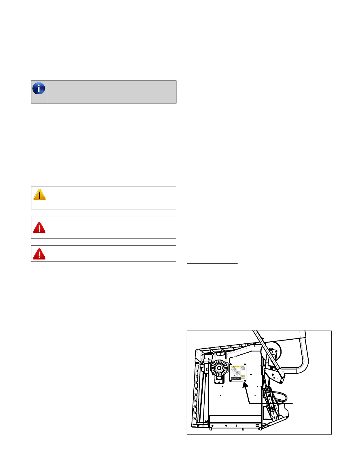
1.3 Decal Information & Placement
Right Side View.
• Decal 128-1244-2 cautions that spindle rotation may
occur with foot pedal depression and to keep clear of
clamping components during shaft rotation.
• Decal 128-964-2 gives the maximum wheel diameter
and maximum wheel weight for balancer
• EN/IEC Class 1 Laser Product Certification is shown
on Decal 128-1638-2.
• An explanation of FDA compliance standards is
shown on Decal 128-1117-2.
Installation of balancer should be completed
only by an authorized Hunter Service
Representative.
CAUTION: Hazards or unsafe practices,
which could result in minor personal injury or
product or property damage.
WARNING: Hazards or unsafe practices,
which could result in severe personal injury
or death.
DANGER: Immediate hazards, which will
result in severe personal injury or death.
128-1244-2
128-1638-2
128-964-2
128-1117-2

Getting Started 6
Figure 1: Right Side View
Figure 2:
Front View
FDA standards for Class 2M laser compliance are shown
on Decal 128-1155-2 (for TDC Units ).
Figure 3: Front View
The Class 2M laser apertures are located at either end of
the TDC header.
Figure 4: Top Dead Center Header
Left Side View
Decal 128-391-2-00 cautions that the unit may automati-
cally start upon closing of the hood when Hood Autostart
is enabled.
Figure 5: : Left Side View
Back View
Decal 128-381-2 warns the operator not to remove the
balancer cover and not to use below garage floor level.
ETL certification standards are outlined on Decal 128-
1120-2.
Figure 6: Back View
128-1155-2
!WARNING!
MA
YSTART
AUTOMATICALL
Y
UPONHOOD
CLOSING
128-391-2-00
128-391-2-00
128-381-2
128-1120-2

Getting Started 7
A manufacturer’s identification label is on the rear of the
balancer.
Figure 7: Manufacturer ID label
Specific Precautions/Power Source
The Road Force® Elite GSP9700 Balancer is intended to
operate from a power source that will apply 230VAC
+10% / -15%, 1 phase, 10 amp 50/60 Hz, power.
The power cable includes a NEMA 20 amp plug, L6-20P,
between the supply conductors of the power cord and uti-
lizes a twist lock connector.
Figure 8: : NEMA L6-20P Plug
Optical Scan Laser Precaution
The Optical Scan Laser is a class 1 laser designed to
measure the profile of wheel assemblies. The laser is not
a field serviceable part. No maintenance is to be per-
formed on the laser.)
Figure 9: Class 1 Laser Warning
Wavelength: 650nm.
HammerHead® TDC Laser Precaution
The TDC (Top Dead Center) Laser Indicator is a class
2M laser designed to aid in applying clip-on weights. This
is an option feature that is not a field serviceable. Laser
Radiation - Do not stare into the beam or view directly
with optical instruments.
Figure 10: Class 2m Laser warning
Turning Power ON/OFF
Push Button Switch.
Balance is equipped with a push button power switch
located on the left side of the LCD support. Use this
switch for normal shut down and restarting procedures.
Figure 11: push button power
A protective ground connection is essential for
safe operation.
YX
G
Always use the push button switch on the LCD
support to power the balancer on/off to prevent
data loss

Getting Started 8
Main Power Switch
The main power ON/OFF switch is located on the back of
the balancer cabinet.
To power the balancer “ON,” press the “I” side of the ON/
OFF switch. To turn all power the balancer “OFF,” press
the “O” side of the ON/OFF switch.
Figure 12: Main Power Switch
Equipment Specifications
Certain Features:
Balancer may include certain features equipment:
• Road Force® uses a roller that applies a load to the
tire in order to take road force measurements
Figure 13: Road Force
• SpeedClamp® pneumatically clamps the wheel onto
the shaft for balancing.
Figure 14: SpeedClamp®
• HammerHead® top-dead-center laser automatically
displays a vivid line at top dead center after a wheel
has been spun.
Figure 15: HammerHead®
Electrical
Voltage: 230VAC +10% / -15%, 1
phase, 50/60 Hz, power cable
includes NEMA 20 amp plug,
L6-20P
Amperage: 10 amperes
Wattage: 3450 watts (peak)
Air
Air Pressure Requirements: 100-175 PSI (6.9-12.0 bar)
Approximate Air Consumption: 4 CFM (113 Liters/Minute)
Atmospherics
Temperature: +32°F to +122°F (0°C to
+50°C)
Relative Humidity: Up to 95% Non-condensing
Altitude: Up to 10000 ft. (3048 m)
Sound Pressure Level
Equivalent continuous A-weighted sound pressure at operator’s
position does not exceed 70 dB (A).

Road Force Elite Main Screen 9
2. Road Force Elite Main Screen
Figure 16:
2.1 Road Force® Elite GSP9700 Main Screen Components
1. Tire Stack / Vehicle Plan View Tab 9. Imbalance and Couple Force Display
2. Load Roller 10. Road Force Limits Display
3. Clip Weight Plane 11. Road Force Wheel Assembly Display
4. Tape Weight Plane 12. Road Force Menu Button
5. Context Sensitive Menu 13. Wheel Dimensions Tab
6. Wheel Assembly Display 14. SmartWeight® Savings Odometer
7. Start / Stop / Servo Button 15. Road Force Savings Odometer
8. SmartWeight® Menu Button 16. Road Force® Menu Button
17. eCal button 18. Vehicle Selection

Balancing Procedures 10
3. Balancing Proce-
dures
3.1 Wheel Lift Operation
Getting Wheel On Balancer
Slide proper collet onto spindle shaft. Position wheel lift
carriage (“lift”) at the end of the lift rail.
Press the foot pedal down to lower lift. Roll wheel onto
the lift. Raise foot pedal to raise wheel into position to
slide it on spindle. Center wheel on collet and clamp.
Keep lift under wheel and close hood. Lift will automati-
cally lower.
Removing Wheel From Balancer
Place lift under wheel and raise it to wheel. Remove
wheel clamp. Slide lift with wheel on it to end of lift rail.
Use pedal to lower lift.
3.2 CenteringCheck® Wheel Center-
ing Feature
CenteringCheck® is an inspection or verification of the
wheel’s mount to balance to identify possible centering
errors. From main balance screen, touch the “Centering-
Check” button and follow the on-screen instructions.
Print Summary
From the main balance screen, select “Print” → “Vehicle
Summary”. The Vehicle Summary screen will be dis-
played.
3.3 Inflation Station
Inflation Station provides preset tire pressure. Lift infla-
tion hose from cradle and setting screen will pop up. Set
target air pressure arrows.
Figure 17: Inflation Station
3.4 Hunter Help Video Player
On main balancer screen, touch Help → Launch Video
Player button. Select balancer topic from video menu.
Figure 18: Video Player
Use two hands to maintain control of the wheel.
Allowing the balancer to lower lift will speed up
removal.

Balancing Procedures 11
4. Calibration & Maintenance
4.1 Auto Calibration
The balancer utilizes an eCal™ automatic calibration procedure. Once the balancer is calibrated at installation time, no
further operator input is required.
4.2 Cleaning the Monitor
To maintain a brand new appearance of the display, clean with soft cloth regularly. Do not touch screen with chemicals/
solvents on fingers. Doing so will damage the screen’s anti-glare protection.Remove stains with a soft cleaner. Corro-
sive cleaner may damage the display. ArmorAll wipes are a suitable cleaning product for the touch screen.
4.3 Maintenance Schedule
4.4 End User License Agreement
Use of balancer and it’s operating software is acknowledgment of agreement to the terms of the End User Licensing
Agreement (“EULA”). The entire EULA can be found by scanning the QR Code below.
Figure 19: Use QR Code to access EULA

Balancing Procedures 12
4.5 Warranty Information

Visit hunter.com/training for more information
Hunter has regional training facilities located
across the country, each providing a variety of
wheel service classes conducted by a full-time
ASE-certified instructor.
Fully-equipped training service bays offer hands-on
practice using the latest Hunter equipment. Heavy-
duty truck alignment facilities offer alignment train-
ing on class 8 trucks and semi-trailers.
Other manuals for Road Force Elite GSP9700 Series
1
Table of contents
Other Hunter Wheel Balancer manuals

Hunter
Hunter SmartWeight Pro Series User manual

Hunter
Hunter SmartWeight Elite User manual

Hunter
Hunter SmartWeight Touch User manual

Hunter
Hunter SmartWeight Pro User manual

Hunter
Hunter GSP9200 Series User manual

Hunter
Hunter DSP9600 User manual

Hunter
Hunter Road Force Touch GSP9700 Series User manual

Hunter
Hunter SmartWeight Pro User manual

Hunter
Hunter GSP9712 User manual

Hunter
Hunter Road Force Elite GSP9700 Series User manual