ATH-Heinl ATH W82 User manual

USER´S MANUAL
ATH W82

© Copyright ATH-Heinl GmbH & Co. KG, 2017, All rights reserved. / Printing errors and technical changing´s reserved / Version: 02/2017
- 2 -
Index
INTRODUCTION .............................................................................................................................- 3 -
General Information ....................................................................................................................- 3 -
General specifications ..................................................................................................................- 4 -
Technical specifications................................................................................................................- 7 -
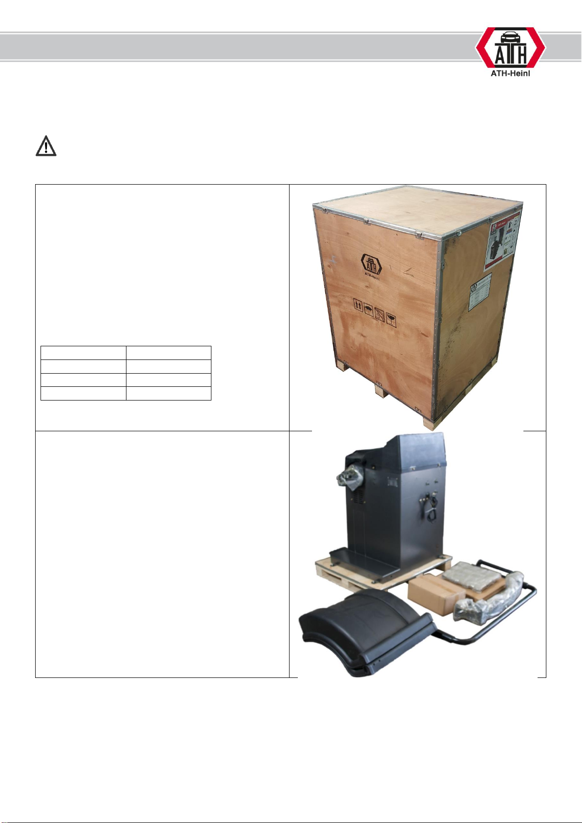
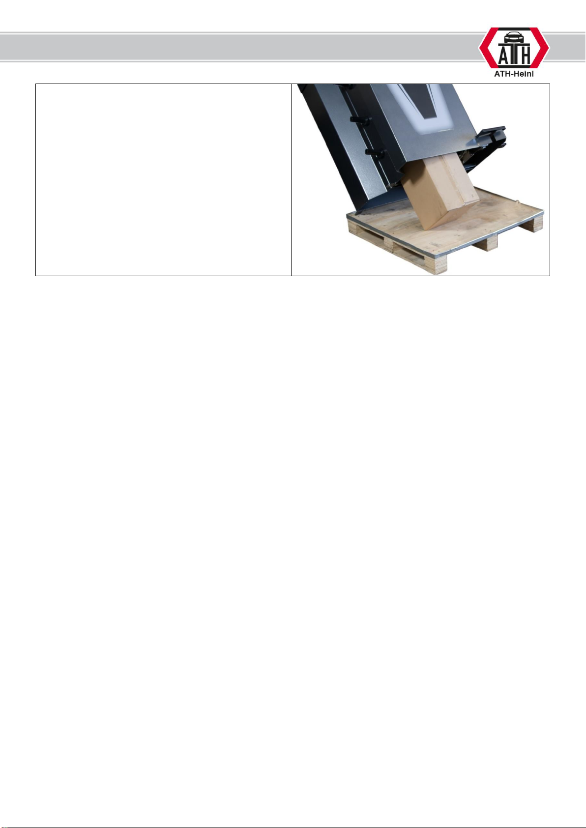
Packing ......................................................................................................................................- 8 -
Scope of delivery.......................................................................................................................- 10 -
INSTALLATION.............................................................................................................................- 13 -
Place of installation ...................................................................................................................- 13 -
Mounting..................................................................................................................................- 14 -
SETTING AND CALIBRATION.........................................................................................................- 23 -
System setting ..........................................................................................................................- 23 -
Calibration menu.......................................................................................................................- 24 -
Calibration of piezo transducer ...................................................................................................- 25 -
Calibration of the measuring device ............................................................................................- 26 -
Calibration of the wheel width measuring device..........................................................................- 28 -
OPERATION .................................................................................................................................- 29 -
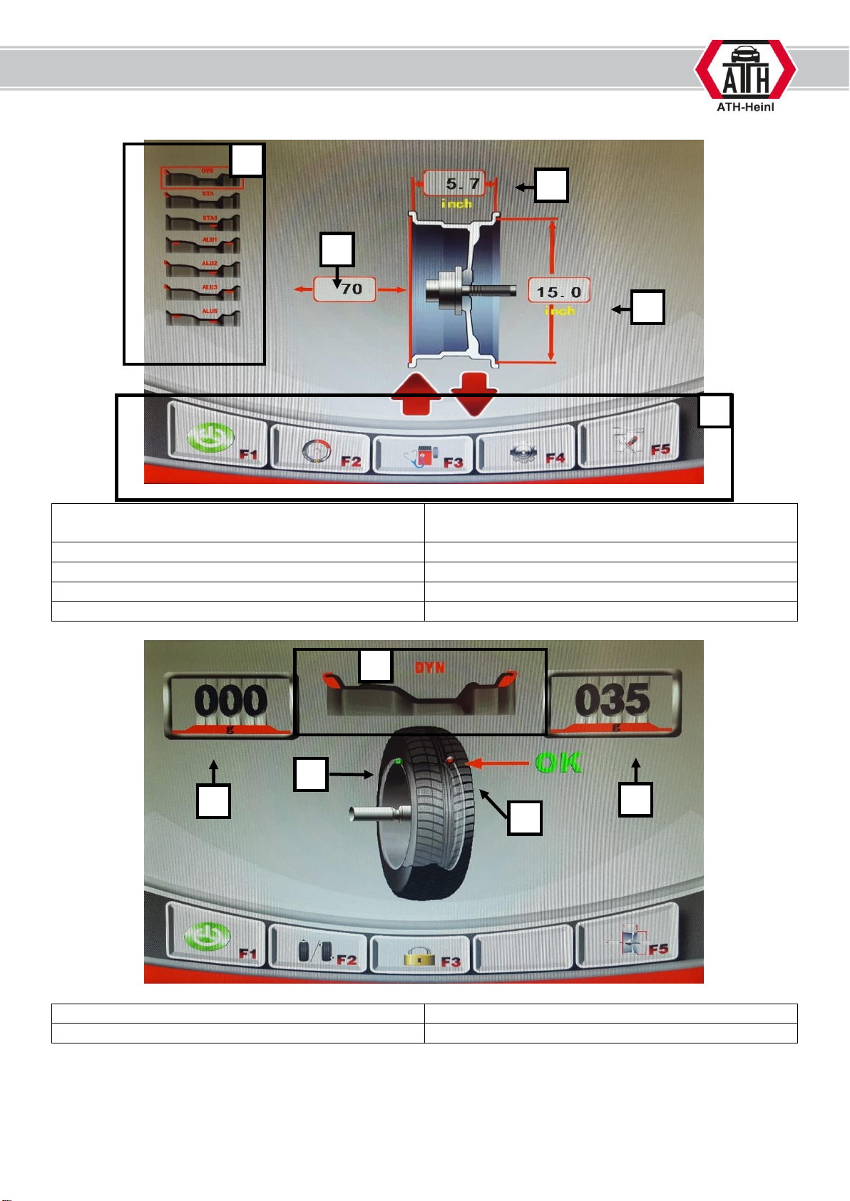
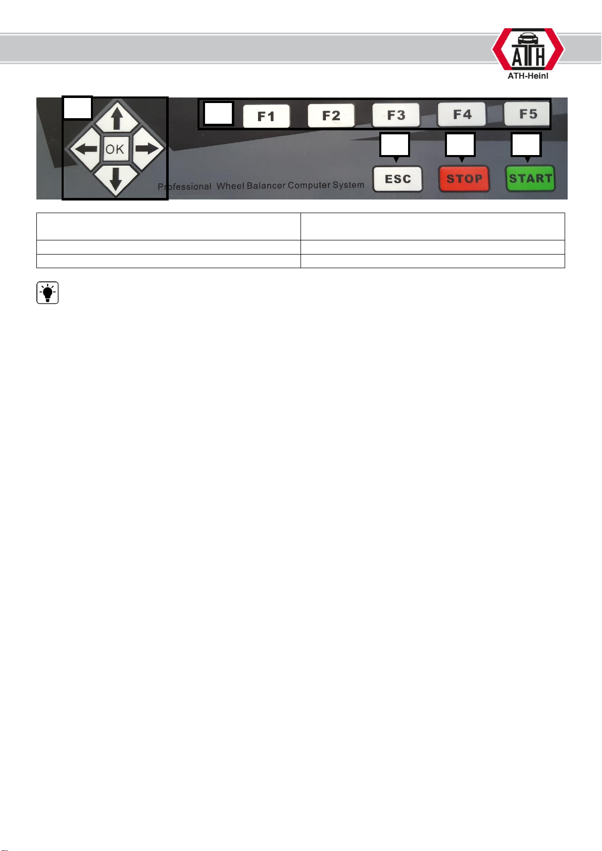
Operation instruction.................................................................................................................- 29 -
Safety instructions.....................................................................................................................- 30 -
Utilization .................................................................................................................................- 31 -
MAINTENANCE .............................................................................................................................- 42 -
Error and remedy......................................................................................................................- 42 -
Troubleshooting........................................................................................................................- 43 -
Maintenance and service instructions ..........................................................................................- 44 -
DECLARATION OF CONFORMITY ...................................................................................................- 46 -
WARRANTY NOTE.........................................................................................................................- 47 -
SPARE PART BOOK .......................................................................................................................- 49 -
Machine ...................................................................................................................................- 50 -
Display.....................................................................................................................................- 52 -
Assistant body ..........................................................................................................................- 54 -
CPU .........................................................................................................................................- 55 -
Display board............................................................................................................................- 56 -
Power board .............................................................................................................................- 57 -
Pneumatic control board ............................................................................................................- 58 -
Air maintenance unit .................................................................................................................- 59 -
Pedal .......................................................................................................................................- 60 -
Solenoid valve...........................................................................................................................- 61 -
Lock cylinder ............................................................................................................................- 62 -
Motor.......................................................................................................................................- 63 -
Photocell ..................................................................................................................................- 64 -
Sensor .....................................................................................................................................- 65 -
Laser probe ..............................................................................................................................- 66 -
Main shaft ................................................................................................................................- 67 -
Balancing shaft .........................................................................................................................- 68 -
Support assembly of wheel cover ...............................................................................................- 69 -
Wheel guard.............................................................................................................................- 70 -
Internal gauge ..........................................................................................................................- 71 -
External gauge..........................................................................................................................- 73 -
Accessories...............................................................................................................................- 75 -
NOTES.........................................................................................................................................- 76 -

© Copyright ATH-Heinl GmbH & Co. KG, 2017, All rights reserved. / Printing errors and technical changing´s reserved / Version: 02/2017
- 3 -
INTRODUCTION
General Information
THIS MANUAL IS AN INHERENT PART OF THE MACHINE.
IT MUST BE READ AND UNDERSTOOD FROM THE OPERATOR.
THERE IS NO RESPONSIBILITY FOR DAMAGES, WHICH ARE RESULTING FROM
NON-OBSERVANCE OF THIS MANUAL OR THE GUILTY SAFETY REGULATIONS.
ATTENTION: Follow the instructions to avoid injuries or damages.
TIP: Gives further information’s to the functions and tips for using the machine efficiently.
Protective clothes must be worn for all works on the described machine.
Name plate:
Note all information’s regarding the tire changer into the following gaps.
It is forbidden to remove the name plate from the tire changer.

© Copyright ATH-Heinl GmbH & Co. KG, 2017, All rights reserved. / Printing errors and technical changing´s reserved / Version: 02/2017
- 4 -
General specifications
1. Main switch with emergency stop function
for switching on and off
2. Cone holder
3. Weights rack
4. Protective bow
5. Measuring device
6. Balancing shaft
7. Display
8. Operation panel
9. Pedal for fixing / loosing of the wheel
10. Rim width measuring device
7
2
1
8
3
5
9
6
4
10

© Copyright ATH-Heinl GmbH & Co. KG, 2017, All rights reserved. / Printing errors and technical changing´s reserved / Version: 02/2017
- 5 -
Display of unbalance:
1) Selection of balancing programs
2) Distance from balancer to first position of
counter-weight
3) Diameter of wheel
4) Width of the wheel
5) Main menu
F1) Start
F2) Optimization program
F3) Diagnosis
F4) Settings
F5) Calibration program
5) Value of unbalance INSIDE
6) Value of unbalance OUTSIDE
7) Location of counter-weight INSIDE
8) Location of counter-weight OUTSIDE
5
7
8
2
1
3
4
6
7
5

© Copyright ATH-Heinl GmbH & Co. KG, 2017, All rights reserved. / Printing errors and technical changing´s reserved / Version: 02/2017
- 6 -
10) Buttons for direction up-down-right-left
[OK]-button
11) Function buttons
12) [ESC]-button to cancel
13) [STOP]-button to exit
14) [START]-button to start
Operate the keys exclusively with your fingers. Never use sharp objects.
11
10
12
13
14

© Copyright ATH-Heinl GmbH & Co. KG, 2017, All rights reserved. / Printing errors and technical changing´s reserved / Version: 02/2017
- 7 -
Technical specifications
Maximum wheel weight
< 65 kg
Wheel diameter
12 - 24 inch
Wheel width
1,5 - 20 inch
Maximum wheel diameter
800 mm
Balancing accuracy
+/- 1 g / 0,1 Oz
Measuring accuracy
>99%
Measuring time
7 - 12 s
Motor
0,25 kW
Electrical system
1/220V/50 Hz
Power consumption
<15W in Standby
Balancing speed
180 rpm
Protection class
IP 54
Noise level
<70 dB(A)
Shaft diameter
40 mm
Balancing programs
Dynamic mode (default)
Static mode
Standard „ALU-1“, „ALU-2“ mode
„ALU-S“ mode
Additional functions
OPT (Optimization) mode
HID (Behind spokes location) mode
Unit set up in g / Oz, mm / inch
Anchoring
Anchor bolts: M8 x 100
Anchor quantity
4 pieces
Dimension of the machine
(L x W x H)
approx. 1330 x 800 x 1700 mm
Weight net / gross
190 / 219 kg

© Copyright ATH-Heinl GmbH & Co. KG, 2017, All rights reserved. / Printing errors and technical changing´s reserved / Version: 02/2017
- 8 -
Packing
Check the goods in the presence of the transporter.
Check the package for visible damage.
In the case of damage or defect, do not accept the goods.
Record the defect and amount of missing parts on the delivery note and report to the supplier.
Instructions for transport and storage:
- Carefully raise the load properly with suitable, in
faultless condition tools.
- Avoid jerks. Beware of bumps, crossbows, etc.
- Keep the removed packing parts in an area which
is inaccessible to children and animals until
disposal.
- Storage temperature: -10°C~+60 °C
- Humidity: 20%-95%
Dimension
Length
850 mm
Width
950 mm
Height
1270 mm
In the picture you will find the current scope of
delivery.

© Copyright ATH-Heinl GmbH & Co. KG, 2017, All rights reserved. / Printing errors and technical changing´s reserved / Version: 02/2017
- 9 -
Additionally, you will find an accessory package
INSIDE the wheel balancer.
To get it you must tilt the machine slightly.
If something is missing in the scope of the delivery
(see packing list), please contact our sales
department.

© Copyright ATH-Heinl GmbH & Co. KG, 2017, All rights reserved. / Printing errors and technical changing´s reserved / Version: 02/2017
- 10 -
Scope of delivery
Two pair of keys for side cover
Wheel guard
Consisting of two plastic parts and one frame
with handle
19 inch LCD Monitor with bracket

© Copyright ATH-Heinl GmbH & Co. KG, 2017, All rights reserved. / Printing errors and technical changing´s reserved / Version: 02/2017
- 11 -
Wheel calliper
Measuring range diameter: 10 –23 inch
Measuring range width: 3 –14 inch
Packing dimensions: 455 x 430 x 50 mm
Mechanism for wheel cover
Screw for fixing of wheel cover
Fixing materials
Packing dimensions: 350 x 230 x 160 mm
Accessory box
Packing dimensions: 385 x 240 x 280 mm
Adhesive weight remover
Counter-weight 5g
Counter-weight 10g
Counter-weight 35g
Counter-weight 50g
Counter-weight 100g
Counter-weight plier
Hex-keys
Cup for quick-nut
Rubber lip for cup
Anchor bolts
Shaft including tension spring

© Copyright ATH-Heinl GmbH & Co. KG, 2017, All rights reserved. / Printing errors and technical changing´s reserved / Version: 02/2017
- 12 -
Screws for shaft
Fixing sleeve
Cone 45 –75 mm
Cone 70 –90 mm
Cone 88 –110 mm
Cone 105 –130 mm
Spacer for Cone 105 –130 mm

© Copyright ATH-Heinl GmbH & Co. KG, 2017, All rights reserved. / Printing errors and technical changing´s reserved / Version: 02/2017
- 13 -
INSTALLATION
Place of installation
Operating temperature:
0-50 °C
Humidity:
≤85% by 30 °C
Sea level
≤1000m
Power connection & grounding cable (see technical data) is too made with plug or direct connection.
Necessary cable
See technical data
The installation of the machine is not allowed in wet rooms as well as in rooms with a risk of
explosion.

© Copyright ATH-Heinl GmbH & Co. KG, 2017, All rights reserved. / Printing errors and technical changing´s reserved / Version: 02/2017
- 14 -
Mounting
This manual is not to be mounting instructions but only as a help for skilled technicians. For the
following works, suitable clothes must be worn and individual safety devices must be made.
An incorrect mounting and setting excludes warranty and liability.
1. Mounting of the wheel balancer
a. Lift the wheel balancer from the pallet, use hereby solely the intended support points. In no
case lift the machine at other points as e.g. the shaft, the display or the accessory plate.
b. The machine must stand firmly on the floor at the intended support points, if necessary
there must be used washers.
2. Fixing with security anchors:
a. Bore holes, pay attention in doing so
to the necessary boring depth A and
the boring diameter of the anchor
manufacturer
b. Clean the inner of the holes
c. Put the anchor bolts into the holes
until you reach the bottom of the
hole.
d. Tighten the nut with the necessary
torque specified by the
manufacturer. Clamping thickness B
depends on flooring.
The wheel balancer must be fixed firmly on the floor for achieving an exact balancing result.

© Copyright ATH-Heinl GmbH & Co. KG, 2017, All rights reserved. / Printing errors and technical changing´s reserved / Version: 02/2017
- 15 -
3. Installing of balancing shaft
Clean the support before installation of the shaft.
Place broth marks on a line.
By help of the finger the user can pressure
the inner shaft to the machine and begin with the
rotation for fixing the shaft.
As soon as the shaft is completely screwed in,
both marks are not in line anymore.
Turn the shaft backwards until the marks are in
line again.

© Copyright ATH-Heinl GmbH & Co. KG, 2017, All rights reserved. / Printing errors and technical changing´s reserved / Version: 02/2017
- 16 -
As soon as the position is correctly the shaft can
be fixed by help of the screws.
4. Installing of wheel cover
Remove the upper cover of the box.
Fixing the mechanism on the balancer chassis by
help of the screws, spring rings and washers.
Connect the mechanism on the specified
connection port. Add cover of the box again on top
and fix it.

© Copyright ATH-Heinl GmbH & Co. KG, 2017, All rights reserved. / Printing errors and technical changing´s reserved / Version: 02/2017
- 17 -
Remove the handle of the frame for the wheel
cover.
Remove the fixing screw on the shaft of the
mechanism.
At first place the backside of wheel cover on the
shaft.
Than take the frame and slide it through the
backside wheel cover onto the shaft.

© Copyright ATH-Heinl GmbH & Co. KG, 2017, All rights reserved. / Printing errors and technical changing´s reserved / Version: 02/2017
- 18 -
Now slide the front side of the wheel cover on the
frame.
Connect both parts together and fix them by using
two screws on the side.
Locate again the fixing screw on the shaft of the
mechanism.
Install the handle on the frame.
5. Install the monitor
Attach the monitor support on the balancer by
using the four screws.
Remove the upper two screws of the cable channel
to place the connection cables of the monitor
inside of this channel.

© Copyright ATH-Heinl GmbH & Co. KG, 2017, All rights reserved. / Printing errors and technical changing´s reserved / Version: 02/2017
- 19 -
Now connect the cables to the balancer.
Install the monitor on the holder by using the four
screws,
Connect the cables to the monitor.
Add again the two top screws on the channel.
6. Install of tire width gauge
Install the support on the frame of the wheel
cover.
Table of contents
Other ATH-Heinl Wheel Balancer manuals

ATH-Heinl
ATH-Heinl W62 User manual

ATH-Heinl
ATH-Heinl ATH 800 User manual

ATH-Heinl
ATH-Heinl W82 User manual

ATH-Heinl
ATH-Heinl W42 User manual

ATH-Heinl
ATH-Heinl ATH W22 User manual

ATH-Heinl
ATH-Heinl W22 User manual

ATH-Heinl
ATH-Heinl W102 User manual

ATH-Heinl
ATH-Heinl W24 User manual

ATH-Heinl
ATH-Heinl ATH 1200 User manual

ATH-Heinl
ATH-Heinl W42 User manual