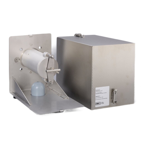
M&C CSS Series User manual

Gas Conditioning Unit Series CSS®
CSS-VC1, CSS-VC2
19“, wall mount or portable in
carrying case with software
version 1.6
Instruction Manual
Version 1.01.03

2 CSS-VC-1.6 | 1.01.03 www.mc-techgroup.com
Dear Customer,
Thank you for buying our product. In this manual you will find all necessary information about this M&C
product. The information in the manual is fast and easy to find, so you can start using your M&C
product right after you have read the manual.
If you have any question regarding the product or the application, please don’t hesitate to contact M&C
or your M&C authorized distributor. You will find all the addresses in the appendix of this instruction
manual.
For additional information about our products, please go to M&C’s website www.mc-techgroup.com.
There you can find the data sheets and manuals of our products in German and English.
This manual does not purport to be complete and is subject to technical
changes.
© 05/2020 M&C TechGroup Germany GmbH. Reproduction of this
document or its content is not allowed without the express permission of
M&C.
CSS ® is a registered trademark.
Version: 1.01.0
3
The original instruction manual is in German.

www.mc-techgroup.com CSS-VC-1.6 | 1.01.03 3
Contents
1General information...................................................................................................................5
2Declaration of conformity..........................................................................................................5
3Safety..........................................................................................................................................6
3.1 Intended Use..........................................................................................................................6
4Warranty .....................................................................................................................................6
5Used Terms and Signal Indications..........................................................................................7
6Introduction................................................................................................................................9
7Application ...............................................................................................................................10
8Technical specifications..........................................................................................................11
8.1 Technical specifications for the expansion modules .............................................................12
8.2 Options.................................................................................................................................13
9Description ...............................................................................................................................16
10 Goods receiving and storage..................................................................................................17
11 Installation instructions...........................................................................................................18
11.1 Conversion to wall mounted or 19" rack housing ..................................................................18
12 Supply connections .................................................................................................................19
12.1 Hose connections.................................................................................................................20
12.2 Lay the connectors on the rear panel....................................................................................21
12.3 Connection of the heated line with antikink adapter for portable version (Art. No. 01G9060
or 01G9061) .........................................................................................................................21
12.4 Electrical connections...........................................................................................................22
12.4.1 Group connection alarm (Part No. 01G6170) ..................................................................22
12.4.2 Connection of individual alarms, external pump control and external cooler
temperature display (Part No. 01G6175).........................................................................23
12.4.3 Connection of heated line for portable version (Part No. 01G6190).................................25
12.4.4 Connecting the optional expansion modules ...................................................................25
13 Commissioning........................................................................................................................25
13.1 Cooler controller ...................................................................................................................26
14 Decommissioning ....................................................................................................................27
15 The multifunctional control unit TCU .....................................................................................27
15.1 Basic functions of the TCU ...................................................................................................27
15.2 Properties of the TCU...........................................................................................................28
15.3 Enhancements to the TCU ...................................................................................................28
15.3.1 The communication module ............................................................................................28
15.3.2 The temperature control module .....................................................................................29
15.3.3 The status module...........................................................................................................30
15.3.4 The backflush module .....................................................................................................31
16 Operation of the multifunctional control unit TCU ................................................................32
16.1 Display of control temperatures or cooling temperature curve ..............................................33
16.2 Configure the switching on and off of the sample pumps......................................................34
16.3 Configure backflushing .........................................................................................................35
16.4 Display of events ..................................................................................................................36
16.5 Operating data......................................................................................................................37
16.6 Resetting service and operating time....................................................................................37
16.7 Setting service interval, language, control temperatures and temperature sensor types.......38
17 Alarms and faults.....................................................................................................................40
17.1 Meaning of the LEDs............................................................................................................40
17.2 Temperature alarms from cooler and temperature control module........................................41
17.3 Flow disturbance and liquid alarms.......................................................................................41
17.4 Other fault and alarm messages...........................................................................................42
18 Maintenance .............................................................................................................................42
18.1 Change the filter elements and O rings.................................................................................43

4 CSS-VC-1.6 | 1.01.03 www.mc-techgroup.com
18.2 Maintenance of the sample gas pump(s) ............................................................................. 43
18.2.1 Remove pump head Type N 3/5/9 KPE.......................................................................... 45
18.2.2 Replacing the diaphragm Type N 3/5/9 KPE ................................................................. 45
18.2.3 Valve plate change Type N 3/5/9 KPE ........................................................................... 45
18.2.4 Mount pump head type N 3/5/9 KPE .............................................................................. 46
18.2.5 CleaningType N 3/5/9 KPE ............................................................................................ 46
18.3 Maintenance of the built-in peristaltic pump type SR 25.2.................................................... 47
18.3.1 Mounting instructions for peristaltic pump....................................................................... 48
18.3.2 Exchange the pump hose............................................................................................... 48
18.3.3 Change of contact pulleys and springs........................................................................... 50
18.3.4 Cleaning the pump head ................................................................................................ 51
18.4 Cleaning of the cooling fins of the compressor cooler .......................................................... 52
19 Spare parts lists ...................................................................................................................... 53
20 Proper Disposal of the Device................................................................................................ 55
21 Appendix ................................................................................................................................. 55
List of figures
Figure 1 Example of a gas flow diagram CSS-VC1................................................................ 10
Figure 2 Dimensions and possible construction CSS-VC....................................................... 16
Figure 3 Connections in the connection panel of the CSS-VC.. ............................................. 19
Figure 4 Connection group alarm........................................................................................... 19
Figure 5 Connecting heated line DN4/6 with antikink adapter ................................................ 21
Figure 6 Plug assignment for the version with group alarm (Part No. 01G6170).................... 22
Figure 7 Upper and lower channel of CSS-VC2..................................................................... 23
Figure 8 Plug assignment for design with individual alarms (Part No. 01G6175) ................... 23
Figure 9 Connection examples for alarm outputs................................................................... 24
Figure 10 Heated line connection for portable version to 10 A ................................................. 25
Figure 11 Electrical connections communication module......................................................... 29
Figure 12 Electrical connections temperature control module.................................................. 30
Figure 13 Electrical connections status module ....................................................................... 30
Figure 14 Electrical connections backflush module.................................................................. 31
Figure 15 Front view of the TCU in normal operation without temperature control module....... 32
Figure 16 Front view of the TCU in normal operation with temperature control module ........... 32
Figure 17 Maintenance of sample gas pump(s) ....................................................................... 44
Figure 18 Sectional drawing N3/5 KPE and N9 KPE................................................................ 44
Figure 19 Components of the peristaltic pump SR25.2............................................................ 47
Figure 20 SR25.2: Mounting distance between front panel and pump motor ........................... 48
Figure 21 Replacing the pump hose ........................................................................................ 49
Figure 22 Disassembly of pump head and driver ..................................................................... 50
Figure 23 Check of axes and rolls............................................................................................ 50
Figure 24 TCU menu ............................................................................................................... 59

www.mc-techgroup.com CSS-VC-1.6 | 1.01.03 5
Headquarters
M&C TechGroup Germany GmbHRehhecke 7940885 RatingenGermany
Tel: 02102 / 935 - 0
Fax: 02102 / 935 - 111
e-mail: info@mc-techgroup.com
www.mc-techgroup.com
1 GENERAL INFORMATION
The product described in this manual has been supplied in a safe and tested condition. For safe
operation and to maintain this condition, the information and instructions in this manual must be followed.
In addition, the appropriate transportation, proper storage and installation as well as careful operation
and maintenance are necessary.
For the proper use of this product, all information required for technical personnel is contained in this
manual.
2 DECLARATION OF CONFORMITY
CE - Certification
The product described in this operating manual complies with the following EU directives:
EMV-Instruction
The requirements of the EU directive 2014/30/EU “Electromagnetic compatibility“ are met.
Low Voltage Directive
The requirement of the EU directive 2014/35/EU “Low Voltage Directive“ are met.
The compliance with this EU directive has been examined according to DIN EN 61010.
RoHS Directive
The requirements of the RoHS2 (‘Restriction of Hazardous Substances 2’) directive 2011/65/EU and its
annexes are met.
Declaration of conformity
The EU Declaration of conformity can be downloaded from the M&C homepage or directly requested
from M&C.

6 CSS-VC-1.6 | 1.01.03 www.mc-techgroup.com
3 SAFETY
Note the following safety precautions when installing, commissioning and operating the device:
Before operation and use of the equipment, read the operating manual. The instructions and warnings
listed in the operating manual must be followed.
Work on electrical equipment must only be performed by qualified personnel in accordance with the
regulations currently in force.
The requirements of VDE 0100 together with its associated standards and regulations must be complied
with for the creation of power installations with nominal voltages up to 1000 V.
When connecting the device, ensure the correct mains voltage in accordance with the specifications on
the rating plate.
Protection against contact with dangerously high electrical voltages:
Before opening the equipment, it must be switched off. This also applies to any connected external
control circuits.
Only use the device in approved temperature and pressure ranges.
Ensure installation is weather-protected. Do not directly expose to dust, rain or liquids.
The device must not be operated in hazardous areas;
Installation, maintenance, monitoring and any repairs must be performed by authorised personnel in
compliance with the relevant provisions.
3.1 INTENDED USE
The CSS-VC1 and CSS-VC2 are intended for use in general purpose areas (non-hazardous
environments).They may only be operated in compliance with the information starting on page 11 in
chapter 8 “Technical specifications”. You must meet the requirements of the ambient temperature and
pressure characteristics in particular.
Do not use this product for any other purpose. Improper use and handling can create hazards and cause
damage. For more information, please refer to the safety information in this instruction manual.
4 WARRANTY
If the device fails, please contact M&C directly, or your M&C authorised dealer.
Provided that the device is used correctly, we undertake to provide a 1 year warranty from the date of
delivery according to our terms of sale. Consumables are not covered by the warranty. The warranty
covers free repair at the factory or free replacement of the device sent free to the point of use. Returns
must be made in sufficient and proper protective packaging.

www.mc-techgroup.com CSS-VC-1.6 | 1.01.03 7
5 USED TERMS AND SIGNAL INDICATIONS
Danger
means that death, serious personal injury and/or substantial property
damage will result if proper precautions are not taken.
Warning
indicates that death, serious personal injury and/or substantial
property damage might occur if proper precautions are not taken.
Caution
means that minor personal injury may result if proper precautions are
not taken.
Caution
without a warning triangle symbol, indicates that property damage
may result if proper measures are not taken.
Attention
indicates that an undesirable result or an undesirable situation may
occur if the corresponding instructions are not followed.
Notice
This is important information about the product or the appropriate part
of the manual to which particular attention should be paid.
Qualified personnel
These are persons with necessary qualification who are familiar with
installation, use and maintenance of the product.
High voltages!
Protect yourself and others against damages which might be caused
by high voltages.
Corrosive!
These substances destroy living tissue and equipment upon contact.
Do not breathe vapors; avoid contact with skin and eyes.
Wear protective gloves!
Working with chemicals, sharp
objects or extremely high
temperatures requires wearing protective gloves.

8 CSS-VC-1.6 | 1.01.03 www.mc-techgroup.com
Wear safety glasses!
Protect your eyes while working with chemicals or sharp
objects.
Wear safety glasses to avoid getting something in your eyes.
Wear protective clothes!
Working with chemicals, sharp objects or extreme
ly high
temperatures requires wearing protective clothes.

www.mc-techgroup.com CSS-VC-1.6 | 1.01.03 9
6 INTRODUCTION
The gas conditioning CSS-VC unit, either for 19 "- or wall mounting or as a portable unit in carrying case,
is a fully pre-assembled compact continuously-operating gas purification system, which, depending on
the design, can supply a sample gas volume of max. 1 x 250 Nl/h (CSS VC1) or 2 x 150 Nl/h (CSS-
VC2). Sample gas conditioning units are suitable due to their equipment and additional options for the
wide-ranging requirements of continuous gas analysis.
The entire gas conditioning unit is housed in a compact, rugged steel housing so that gas analyses can
be performed rapidly without a great deal of effort, with low maintenance and reliability.
Gas conditioning unit CSS-VC must not be used to support gas/air or gas/oxygen mixtures that are
ignitable during operation, for the supply of combustible gases that can form an ignitable mixture in
combination with air or oxygen, or in potentially explosive atmospheres and in potentially explosive
locations.

10 CSS-VC-1.6 | 1.01.03 www.mc-techgroup.com
7 APPLICATION
With the CSS-VC, fully pre-installed gas conditioning systems are created for continuous use, which can
be integrated perfectly into analytical systems. The compact design makes few demands on space. The
gas conditioning systems are operational within minutes. This renders time-consuming and expensive
procurement of individual components and small parts and their assembly unnecessary. A portable
version is also available in a carrying case.
Figure 1 Example of a gas flow diagram CSS-VC1
Gas cooler series ECM-1
Option universal filter or front-installed filter FPF-0, 1GF, 0.1 μm, with optional liquid alarm LA or
front-installed filter FPF-2-0, 3GF, 0.3 μm, with integrated humidity alarm
Option 3 or 5-way ball valve 3L/PV or 5L/PV
Option sample gas pump N3/5/9KPE
Option peristaltic pump SR25.2
Option flow meter FM40 with flow alarm
Option flow meter FM40
Option liquid particulate filter CLF-5/W or CLF-T (SS)
In version CSS-VC2there are 2 parallel gas lines in one gas conditioning unit.

www.mc-techgroup.com CSS-VC-1.6 | 1.01.03 11
8 TECHNICAL SPECIFICATIONS
Gas conditioning series CSS ® Version CSS-VC1 Version CSS-VC2
Article number 230 V 50 Hz
01G6050
01G6055
Article number 115 V / 50-60 Hz
01G6050a
01G6055a
Gas outlet dew point
Setting range: + 2 °C ..... + 7 °C [35.6 … 44.6 °F],
factory setting: + 5 °C [41 °F]
Dew point stability
Under constant conditions < ± 0.1 ° C [±0.18 °F]
Gas inlet temperature
Max. 180° C** [356 °F]**
Gas inlet water-vapour saturation
Max. + 80 ° C** [176 °F]**
Gas flow
**Max. 250 Nl/h
**Max. 2 x 150 l/h
Ambient temperature
10 to + 40 °C** [50 to 104 °F]**
Storage temperature
-25 to + 65 °C [-13 to 149 °F]
Pressure
0.7 bar to 1.4 bar abs.
Total cooling capacity **
Max. 144 kJ/h
Number of gas inlets
1
2
Number of gas outlets
1
2
Condensate connection
1
2
Medium connections
Hose connection 4/6 mm
Material of parts in contact with
medium
Heat exchangers: Glass, PVDF or stainless steel 1.4571
Hoses/screwed connectors: PTFE/PVDF
Universal filter e.g. FP-2T-D: PVDF, FPM, glass, PTFE
Front-installed filter FPF-0.1GF: PVDF, glass, FPM
Front-installed filter FPF-2-0.3GF: PVC, FPM, PPH
Peristaltic pump SR25.2: PVDF, Novoprene ®
Liquid particle e.g. CLF-5/W: PVDF, glass, FPM, PTFE
Sample gas pumps N3/5/9: PVDF, PTFE, FPM
Flow meter FM40: PVDF, glass, FPM, Hastelloy C4
Ball valve 3L/PV and 5L/PV: PVDF, FPM
Operational
Approx. 10 minutes.
Mains connection
230 V 50-60 Hz ±10 % or 115 V 50-60 Hz ±10 % ***
Power input
Max. 220 VA + max. 300 VA for sample gas pumps
Device fuse
6.3 A time-lag, 5 x 20 mm
Electrical connection
- Cold-device connector with 2 m cable
- Single alarm connections (11 & 12-pole) or status alarm(s)
(6-pole) : maximum capacity of the relays 24 V 500 mA
- mA-outlet : maximum load 500 Ohm, accuracy ±2 % of
measuring range end value for display indication
- M&C Bus
- Heated sample line : maximum length 10 m [≈ 82.81 ft]
Device protection class IP20 to EN 60529
Housing design
Steel housing for 19"- or wall mounting, painted RAL 7035
Device dimensions (H x W x D)
267.5 x 483 x 301.5 mm [≈ 10.53” x 19.02” x 11.87”]
(Portable version: 355 x 515 x 395 mm [≈ 13.98” x 20.28” x 15.55”])
Electrical device standard
EN 61010
FPM = Viton ®
PVDF = Polyvinylidene fluoride
PVC = Polyvinyl chloride
FPM = Fluorinated rubber
PPH = Hard polypropylene
PTFE = Polytetrafluoroethylene
**Technical specifications with maximum values must be rated in consideration of total cooling capacity at 25 °C [77 °F] and an outlet dew point of 5 °C [41 °F].
*** 115 V / 50 Hz sample gas pump available as a special item

12 CSS-VC-1.6 | 1.01.03 www.mc-techgroup.com
8.1 TECHNICAL SPECIFICATIONS FOR THE EXPANSION MODULES
Module
Communication module
Status module
Temperature control module Backflush module
Part No.
91B8620
91B8630
91B8640
91B8650
Power supply 24 V DC ±20 % internal
Earthing L < 3 m [≈ 9.84 ft]
-
L < 3 m [≈ 9.84 ft]
Communication
M&C system bus (RJ-45)
L < 3 m [≈ 9.84 ft]
- - -
Inputs
2 x PT100 (2-wire)
L < 30 m [≈ 98.4 ft] or
2 x thermocouples
L < 30 m [≈ 98.4 ft]
- - Switching input
(Pressure switch)
Connection cable
length
see above - - Max. 100 m [≈ 328.1 ft]
Outputs -
Function: Status
1 potential-free
contact
(Changeover
switch 230 V AC
1 A)
(Can be used up
to 24 V, 500 mA!)
1 solid-state
output
230 V AC 3 A
Function: Pump1
1 solid state
output
230 V AC 3 A
Function: Pump 2
1 solid-state
output
230 V AC 3 A
2 x small signal digital output for
solid state relay control
24 V max. 20 mA
Function: High temperature
alarm
2 potential-free contacts
(N/O contact 230 V AC 1 A)
(can be used up to 24 V
500 mA!)
Function: Low temperature
alarm
2 potential-free contacts
(N/O contact 230 V AC 1 A)
(can be used up to 24 V
500 mA!)
Function: Measurement
1 potential-free contact
(Changeover switch
48 V AC 1 A)
(can be used up to 24 V
500 mA!)
Function: Backflush 1
1 solid-state output
230 V AC 3 A
Function: Control air
1 solid-state output
230 V AC 3 A
Function: Backflush 2
1 solid state output
230 V AC 3 A
Connection cable
length
- Max. 100 m [≈ 328.1 ft]
Ambient temperature
max.
+ 60 ° C [140 °F]
Dimensions: 72 x 88 x 20 mm
[≈ 2.8” x 3.5 x 0.78”]
72 x 68 x 30 mm
[≈ 2.8” x 2.7” x
1.2”]
72 x 68 x 18 mm
[≈ 2.8” x 2.7” x 0.7”]
72 x 79 x 30 mm
[≈ 2.8” x 3.1” x 1.2”]
Weight 90 g [≈ 0.2 lb] 100 g [≈ 0.22 lb] 48 g [≈ 0.11 lb] 106 g [≈ 0.23 lb]
The power consumption of all modules together is max. 140 mA at 24 V => 3.36 W.

www.mc-techgroup.com CSS-VC-1.6 | 1.01.03 13
8.2 OPTIONS
Beyond the standard scope of options of this for the CSS-VC, other customised options are possible
that cannot be listed in this manual.
Description Part No.
Extra charge for gas connections directly to a heat exchanger
01G6062
Extra charge for glass heat exchanger ECM-1 for CSS-VC1, sample gas connections on the
heat exchanger
93K0140
Extra charge for stainless steel heat exchanger ECM-1 for CSS-VC1, sample gas connections
on the heat exchanger
93K0160
Extra charge for PVDF heat exchanger ECM-1 for CSS-VC1, gas connections on the heat
exchanger
93K0170
Extra charge for gas connections directly to two heat exchangers
01G6063
Extra charge for glass heat exchanger ECM-2 for CSS-VC2, sample gas connections on the
heat exchangers
97K0100
Extra charge for stainless steel heat exchanger ECM-2 for CSS-VC2, sample gas connections
on the heat exchangers
97K0115
Extra charge for PVDF heat exchanger ECM-2 for CSS-VC1, sample gas connections on the
heat exchangers
97K0110
Extra charge for gas connections of a heat exchanger in the connection plate for e.g. 19" mount
01G6060
Extra charge for glass heat exchanger ECM-1 90 ° for CSS-VC1, sample gas connections in the
connection plate for e.g. 19" mount
93K0150
Extra charge for PVDF heat exchanger ECM-1 90° for CSS-VC1 sample gas connections in the
connection plate for e.g. 19" mount
93K0170
Extra charge for gas connections of 2 heat exchangers in the connection plate for e.g. 19" mount
01G6061
Extra charge for glass heat exchanger ECM-2 90° for CSS-VC2 sample gas connections in the
connection plate for e.g. 19" mount
97K0150
Extra charge for PVDF heat exchanger ECM-2 90° for CSS-VC2 sample gas connections in the
connection plate for e.g. 19" mount
97K0110
Extra charge for gas connections directly to a heat exchanger
01G6062
Extra charge for glass heat exchanger ECM-1 for CSS-VC1, sample gas connections on the
heat exchanger
93K0140
Extra charge for stainless steel heat exchanger ECM-1 for CSS-VC1, sample gas connections
on the heat exchanger
93K0160
Extra charge for PVDF heat exchanger ECM-1 for CSS-VC1, gas connections on the heat
exchanger
93K0170
Extra charge for gas connections directly to two heat exchangers
01G6063
Extra charge for glass heat exchanger ECM-2 for CSS-VC2, sample gas connections on the
heat exchangers
97K0100
Extra charge for glass heat exchanger ECM-2 for CSS-VC2, sample gas connections on the
heat exchangers
97K0100

14 CSS-VC-1.6 | 1.01.03 www.mc-techgroup.com
Description Part No.
Peristaltic pumps for condensate disposal (max. 2 pcs.)
Extra charge for mounting a peristaltic pump SR25.2 for condensate disposal, with hoses pre-
installed (one required for each gas line)
01G6140
Filter (max. 2 pcs. Front-installed filters and 2 pcs. Universal or aerosol filters) and liquid alarm (max. 2
pcs.)
Extra charge for installation of a sample gas filter FPF-0, 1GF
04F1000
Extra charge for liquid alarm with flow chamber LS/LA2 with sample gas filter FPF-0, 1GF
03E3010
Extra charge for installation of a sample gas filter FPF+
04F2100
Extra charge for filter element for FPF+ (see datasheet 7.2a)
According
to choice
Extra charge for liquid sensor LA3 integrated into FPF+
03E1300
Extra charge for universal filter (see data sheet 7.1)/aerosol filter CLF... (see data sheet 7.7 and
7.8)
According
to choice
Extra charge for installation of universal filter/aerosol filter CLF on front plate (max 2 pcs.)
01G6075
Extra charge for liquid alarm LA1S with universal filter F. -..-D
03E1001
Ball valves for calibration gas feeding (max. 1 pc.)
Extra charge for installation of a 3-way ball valve 3L/PV
01G9045
Extra charge for installation of a 5-way ball valve 5L/PV
01G9046
Sample gas pumps (max. 2 pcs., only with evaluation electronic system 01 G 6175)
Extra charge for installing sample pumps N.. KPE
01G6070
Extra charge for sample gas pump N3KPE
01G6125
Extra charge for gas pump N5KPE
01G6130
Extra charge for gas pump N9KPE
01G6135
Flow meter (max. 4 pc. total) and flow alarm (max. 2 pcs.)
Extra charge for installation of a flow meter FM40 7-70 Nl/h in the sample gas outlet
09F4000
Extra charge for installation of a flow meter FM40 15-150 Nl/h in the sample gas outlet
09F4005
Extra charge for installation of a flow meter FM40 25-250 Nl/h in the sample gas outlet
09F4010
Extra charge for installation of a flow meter FM40 50-500 Nl/h in the sample gas outlet
09F4015
Extra charge for flow alarm with forked light barrier FA-20mo
02E3500
Extra charge for second sample gas output or bypass flow meter FM40 7-70 Nl/h
01G6200
Extra charge for second sample gas output or bypass flow meter FM40 15-150 Nl/h
01G6210
Extra charge for second sample gas output or bypass with flow meter FM40 25-250 Nl/h
01G6220
Extra charge for second sample gas output or bypass flow meter FM40 50-500 Nl/h
01G6230
Electronic evaluation system
Extra charge for electronic evaluation system with group status alarm
01G6170
Extra charge for electronic evaluation system with individual alarm (temperature, flow, liquid in
system) including MA output for cooler temperature for external temperature display
01G6175

www.mc-techgroup.com CSS-VC-1.6 | 1.01.03 15
Description Part No.
External expansion modules (only with electronic evaluation system 01G6175)
Extra charge for communication module (one-time necessity for all expansion modules of the
TCU)
01B8620
Extra charge for temperature control module (2 additional thermostats in TCU with 4 relays for
high or low temperature monitoring) for controlling solid-state relays
01B8640
Extra charge for status module for group alarm via 1 changeover relay and 1 solid-state relay for
switching external sample gas pumps
01B8630
Description Part No.
Extra charge for backflush module for programmed control of solenoid valves for backflushing of
gas probes with status monitoring (measuring/backflush), monitoring of backflush pressure and
control of the sample pumps (on/off)
01B8650
Extra charge for M&C bus for external modules
01G6180
Transport case (19" version only)
Extra charge for carrying case for portable gas conditioning
01G6250
Temperature controller for portable version (only with electronic evaluation system 01G6175)
Extra charge for thermostat for maximum 10 m [≈ 32.8 ft] heated line, 230 V with PT100, with
solid-state relays and 7-pin connector
01G6190
Kink protection for portable gas conditioning
Extra charge for kink protection for heated line DN4/6
01G9060
Extra charge for kink protection for heated line DN6/8
01G9061

16 CSS-VC-1.6 | 1.01.03 www.mc-techgroup.com
9 DESCRIPTION
Figure 2 Dimensions and possible construction CSS-VC..
Fine filter FPF-0, 1GF
Flow meter FM40 with and without forked light barrier FA-20mo
Multifunctional expandable controller unit TCU
Peristaltic pumps SR25.2 with condensate output at the pump
Sample gas inputs and outputs DN4/6 in connection plate or sample gas inputs on the heat
exchanger
Connection of group alarms (temperature, flow, liquid penetration)
Cold-device socket
3 or 5-way ball valve for calibration gas feeding or 3L/PV or 5L/PV
M&C bus interface
Aerosol filter CLF..
All components of the gas conditioning systems are installed in a strong compact steel housing for wall
or 19" mount. The ventilation grilles in the side walls provide adequate forced ventilation.
Filter, flow meter and peristaltic pumps are located in the front panel and thus ensure very simple main-
tenance. Due to a removable lid and a hinged front panel, quick and easy inspection and maintenance
of all other built-in components is possible, in particular the easy changing of heat exchangers.
The compressor gas cooler can be equipped with one or two heat exchangers made of glass, stainless
steel or PVDF.
Peristaltic pumps of type SR25.2 are used for continuous condensate removal or as a metering pump.
The current cooler temperature is displayed on the multi-functional control unit TCU mounted on the
front panel. The setpoint temperature of the cooler can be set by pressing keys. In the event of warnings

www.mc-techgroup.com CSS-VC-1.6 | 1.01.03 17
or faults, plain text information appears on the display and is also indicated by LEDs (e.g. cooler within
the setpoint range and no other alarms - green LED, flow alarm (option) - yellow LED, temperature ±3° C
[±5.4 °F] from the setpoint and humidity alarm (option) - red LED).
The fine filter downstream of the cooler (different filter types available) provides for the necessary
separation of solids. The condition of the filter can be judged from the outside. To protect the
downstream analysers against liquid penetration and to increase the operating reliability of the whole
system, according to the selected filter type, a suitable liquid alarm is possible or already integrated into
the filter.
A group alarm or on request individual alarms including mA output for the cooler temperature at the
output terminals is available wired. Via potential-free contacts for the group alarm or the individual
alarms (cooler temperature, flow, fluid in the system), an alarm message and shutdown of the sample
gas pump, if present, occurs.
Integrated sample gas pumps are available in three performance levels to choose from N3/5/9 KPE.
The flow meter FM40 arranged in the sample gas outlet with a measuring range adapted to the pump
power can be supplied for flow monitoring with a flow sensor FA-20mo. In addition, each sample gas
line can be equipped with a second sample gas outlet or bypass flow meter and flow control.
In the event of an aerosol problem, a liquid particulate filter CLF can be added downstream of the flow
meter in the sample gas outlet.
Via expansion modules for the control unit TCU two further temperature controllers are available e.g. to
regulate heated lines or gas probes. Here too external sample gas pumps can be connected and indi-
vidual sample gas probes can be backflushed.
10 GOODS RECEIVING AND STORAGE
The gas conditioning unit CSS-VC.. is a fully pre-assembled unit. In addition there are included:
1 x connection cable
1 x 6-pin or 11 and 12-pin connector
Optional 2 - 4 expansion modules
•Immediately after arrival carefully remove the CSS-VC.. and any special accessories from the
dispatch packaging and check the supplied items in accordance with the delivery note and the list;
•Check the goods for shipping damage and, if necessary, inform your transport insurer immediately
of any damage.
Notice
Storage of the gas conditioning unit should be in a sheltered frost-free room!

18 CSS-VC-1.6 | 1.01.03 www.mc-techgroup.com
11 INSTALLATION INSTRUCTIONS
Notice
So that the unit is safe and operates reliably, it should be mounted horizontally
and without vibration. Only then is proper separation and drainage of the
condensate in the heat exchanger of the cooler ensured.
The mounting of the gas conditioning unit should take place away
from heat
sources and be freely ventilated so that there can be no disruptive
accumulation of heat.
When installed outdoors, adequate protection against direct sunlight and
moisture needs to be ensured. In winter, the place of installation must be frost-
free; ensure correct protection for the device.
Temperature variations, strong air movement and aggressive atmospheres at
the place of installation are to be avoided.
To ensure safe operation of the gas conditioning unit and downstream
analysers and to av
oid false alarms, the gas conditioning unit should not be
used outside the specified temperature range. It must also be protected
against the ingress and accumulation of dust.
Downstream analysers and lines must operate at temperatures significantly
above the specified gas outlet dew point of +5 °C [41 °F]
. This will avoid
subsequent condensation of the gas in the connecting lines to the analysers.
Unheated gas sample lines must be laid on a slope to the cooler.
11.1 CONVERSION TO WALL MOUNTED OR 19" RACK HOUSING
Gas conditioning units CSS-VC.., if not in a carrying case, are delivered with wall-mounting or 19"
housing.
Depending on which housing is required, the gas conditioning unit can be converted very simply by
moving the mounting bracket:
•Remove two screws per bracket
•Align bracket to the mounting holes according to the desired housing forward or rearward
•Secure the bracket flush with the housing panel (19" mounting) or with protrusion to the rear
(wall mounting) with the two fixing screws on the housing

www.mc-techgroup.com CSS-VC-1.6 | 1.01.03 19
12 SUPPLY CONNECTIONS
Figure 3 Connections in the connection panel of the CSS-VC..
Depending on the version of the CSS-VC, instead of the 11 and 12-pin connector for single alarms, mA
output cooler temperature and external sample gas pump control, a 6-pin connector may also be present
for group alarm (see Figure 4 ). The sample gas inlet, depending on the version, may also lie directly on
the heat exchangers.
Figure 4 Connection group alarm
In the portable version of the CSS-VC.., the supply connectors shown above are located on the rear
panel of the housing. The RJ45 connector is not present here. With the temperature controller option for
the portable version (Part No. 01G6190), a 7-pin connector (see section 12.4.3) is present at the position
of the RJ45 connector in Figure 3.

20 CSS-VC-1.6 | 1.01.03 www.mc-techgroup.com
12.1 HOSE CONNECTIONS
The connection of the sample gas input, depending on the connection type, is directly on the heat
exchanger or on the clamping plate.
Notice
Do not confuse the hose connections. They are marked appropriately.
After connecting all the lines, they should be checked to ensure there are no
leaks.
The condensate connections are made directly to the hose pump.
All hose connections are standard DN4/6 mm ferrule hose fittings made of PVDF, for gas inlet
temperatures up to 105° C [221 °F] (see section 8).
Installation of the sample gas hoses or the condensate hose must be carried out as follows:
•Loosen the clamping ring screwed fitting counterclockwise; It is important to ensure that the nut is
carefully removed from the threaded joint, so that the loose clamping ring which is in the nut is not
lost;
•Slide the nut over the hose connection;
•Slide the clamping ring with the thicker bulge facing the nut, onto the connection hose;
•Attach the hose to the nipple in the threaded support;
Notice
The tightness of the connection can only be guaranteed if the hose has
a straight end edge (using a hose cutter).
•Hand-tighten the nut.
The hose is now mounted slip-proof and pressure-tight.
The dismantling of the hoses is carried out in the reverse order.
Warning
Possible aggressive condensate.
Wear protective glasses and proper protective clothing!
Other manuals for CSS Series
4
This manual suits for next models
2
Table of contents
Other M&C Laboratory Equipment manuals