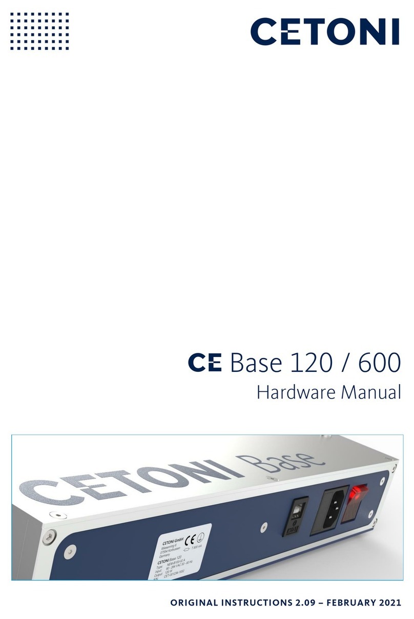
cetoni BASE 120 User manual

SYSTEM
Hardware Manual –General Part
ORIGINAL INSTRUCTIONS 1.01 –MAY 2020

2CETONI System Hardware Manual
CETONI GmbH
Wiesenring 6
07554 Korbussen
Germany
T+49 (0) 36602 338-0
F+49 (0) 36602 338-11
www.cetoni.de

CETONI System Hardware Manual 3
The information and data contained in this document are subject to change without notice. CETONI
GmbH is constantly striving to develop all its products. This means that there may be changes in form,
equipment and technology. Claims can therefore not be made on the basis of information, illustration or
descriptions in these instructions. The description for the product specification in this manual does not
constitute an integral part of the contract.
If you control the products with software from CETONI GmbH, you agree to the applicable license
agreement, which can be read in the corresponding software manual. This and all other current product
manuals can be found at https://www.cetoni.de/en/downloads/manuals.
CETONI GmbH grants its customers the right to reproduce this manual for the purpose of providing
technical information to potential users of CETONI products. Extracts of these documents may only be
reproduced or transmitted with a precise reference to the authorship of CETONI GmbH, irrespective of
the manner in which they are reproduced or transmitted, either electronically or mechanically. Any
duplication or use of excerpts for other purposes requires the written permission of CETONI GmbH.
We are always open to comments, corrections and requests. Please send them to info@cetoni.de.
The general terms and conditions of CETONI GmbH shall apply. Alternative agreements must be in
written form.
Copyright © CETONI GmbH –Automation and Microsystems. All rights reserved.

4CETONI System Hardware Manual

CETONI System Hardware Manual 5
1Overviews and Indexes
1.1 Content
1Overviews and Indexes 5
1.1 Content 5
1.2 Change History 6
2Introduction 7
2.1 Foreword 7
2.2 Symbols and Keywords Used 7
2.3 Norms and Guidelines 8
2.4 Application Purpose 8
2.4.1 General Description of the Device 8
2.4.2 Intended Use 8
2.4.3 Reasonably Foreseeable Faulty Application 8
2.4.4 Safety Advice 8
2.4.5 Measures for Safe Operation 10
2.4.6 Safety Devices on the System 10
2.4.7 Condition of the Devices 10
2.5 Warranty and Liability 11
3Initial Start-up 12
3.1 Unpacking and setting up the system 12
3.2 Installing software 14
3.3 Connecting the base module 15
3.4Creating a device configuration 16
3.5 Configuring single modules 18
3.6 Assembling the complete system and connecting it to the software 19
3.7 Separating modules 22
4Transport and Storage 23

CETONI System Hardware Manual 7
2Introduction
2.1 Foreword
Thank you for choosing a CETONI product. With this user manual we would like to support you in
handling the CETONI products and devices. If you have any further questions or suggestions, please do
not hesitate to contact us directly.
The complete system may only be put into operation after thorough reading of this manual. We wish
you much success in working with the CETONI system.
2.2 Symbols and Keywords Used
The following symbols are used in this manual and are designed to aid your navigation through this
document:
HINT. Describes practical tips and useful information to facilitate the handling of the
software.
IMPORTANT. Signifies important hints and other useful information that may not
result in potentially dangerous or harmful situations.
CAUTION. Identifies a potentially harmful situation. Failure to avert this situation may
result in damage to the product or anything in its proximity.
ATTENTION. Indicates a potentially dangerous situation. Failure to avert this situation
may result in light or minor injuries or property damage.

8CETONI System Hardware Manual
2.3 Norms and Guidelines
CETONI GmbH declares under its sole responsibility, that all devices of the system
comply with the health and safety requirements of the relevant European directives.
2.4 Application Purpose
2.4.1 General Description of the Device
The CETONI system is a modular system of different devices for performing various processes and
applications in laboratories.
2.4.2 Intended Use
The devices of the CETONI system are intended for the use described in the corresponding device
manuals.
2.4.3 Reasonably Foreseeable Faulty Application
A use for applications distinct from the intended purpose can lead to dangerous situations and is to be
omitted.
CAUTION. The unit must not be used as a medical device or for medical purposes.
2.4.4 Safety Advice
The safety of the user and a failure-free operation of the devices are assured only if original parts are
used. Only original accessories may be used. Warranty claims will not be accepted for damage due to
the use of alien accessories or expendables.
The devices have been developed and constructed in such a way as to largely rule out hazards due to its
intended use. Nevertheless, you must observe the following security measures in order to exclude any
remaining hazards.
CETONI GmbH points out the responsibilities of the operator for the operation of the devices.
The laws and regulations of the place of installation must be observed while operating the

CETONI System Hardware Manual 9
devices! To ensure a safe work routine, operators and users must assume responsibility for
adhering to regulations.
The devices must not be used as a medical device or for medical purposes.
The CETONI system is designed and approved to work in fluidic systems, which fall within the
scope of Article 4 Para. 3 of the Pressure Equipment Directive 2014/68/EU.
This means that the system may not exceed a maximum volume of 1 liter. With the use of fluids
from Group 1 according to Article 13, Para. 1 of the Pressure Equipment Directive 2014/68/EU,
the maximum allowable system pressure is 200 bar. For fluids from Group 2 it is 1000 bar. If
different, product-specific values for the maximum pressure are given in the section "Technical
Data", these values must be complied with. Regarding the maximum operating temperature, the
specification from the section "Technical Data" must be observed.
CETONI GmbH is not liable for consequences that may arise if the user expands the system by
peripheral devices, such that one of the values or both values are exceeded.
It is the user's responsibility to become familiar with the mentioned Pressure Equipment
Directive and to comply with the prevailing requirements.
Before operating the unit, the user must at all times ensure the operational reliability and the
adequate and orderly condition of the unit.
The user must be familiar with the operation of the devices and the software.
The devices and pipes must be checked for damage before operation. Damaged pipes and plug
devices must be replaced immediately.
Cables must be laid in a way that avoids any risk of stumbling.
Any moving parts must not be touched whilst the devices are in operation. There is a risk of
crushing!
Any parts that may be hot or cold must not be touched whilst the devices are in operation.
There is a risk of a burn or frostbite!
It is not allowed to use the devices in an explosive atmosphere or with potentially explosive
substances.
Wear protective glasses if you are working with corrosive, hot or otherwise dangerous
substances during assembly work on the device.
Transportation, storage or operation of the devices below 0°C with water in the fluid passages
may cause damage to the modules.

10 CETONI System Hardware Manual
2.4.5 Measures for Safe Operation
2.4.5.1 ELECTROMAGNETIC EMISSIONS
The CETONI system is intended for use in any type of facility, connected directly to the public power
supply network that supplies buildings used for domestic purposes.
2.4.5.2 ELECTROSTATIC DISCHARGE
Floors should be made of wood, concrete, or ceramic tiles. If the flooring is made of a synthetic material;
the relative humidity must be at least 30%.
2.4.5.3 ELECTRIC DISTURBANCES
The quality of the supply voltage should be to the standard of a typical business or hospital
environment.
2.4.5.4 MAGNETIC DISTURBANCES
Do not place power connector cables, even of other appliances, in close proximity of the devices and
their cables. Mobile communication devices may not be used in closer proximity of the devices or their
cables than the recommended safety distance!
2.4.6 Safety Devices on the System
The system can be switched off at any time in an emergency using the mains switch on the Base
Module (toggle switch on the side of the housing); this will cause no damage to the unit.
2.4.7 Condition of the Devices
Irrespective of the faultless manufacture of the devices, damage can occur whilst the unit is in
operation. With this in mind, always carry out a visual check of the components mentioned before use.
Pay particular attention to crushed cables, damaged tubing, and deformed plugs. If you should notice
any damage, please do not use the devices and inform CETONI GmbH without delay. CETONI will put
your devices back to an operational condition at the earliest. Do not attempt to repair the devices
yourself.

CETONI System Hardware Manual 11
2.5 Warranty and Liability
The devices left our company in perfect condition. Only the manufacturer is permitted to open the
devices. All guarantee and liability entitlements, particularly damage entitlements due to personal
injuries, are void if the devices are opened by an unauthorised person.
The duration of the warranty is 1 year from the day of delivery. It is not extended or renewed due to
work carried out under warranty.
CETONI GmbH considers itself responsible for the devices with regard to safety, reliability and function
only if assembly, new settings, changes, extensions and repairs are carried out by CETONI GmbH or an
authorised centre, and if the devices have been used in accordance with the instruction manual.
The CETONI system conforms to the basic safety regulation standards. Industrial property rights are
reserved on the circuits, methods, names, software programs, and units.

12 CETONI System Hardware Manual
3Initial Start-up
3.1 Unpacking and setting up the system
Set up your individual CETONI devices, initially without plugging them together or connecting them to
each other, on a flat, horizontal surface, e.g. table, base cabinets or equipment trolleys. You can set up
the system both horizontally and vertically.
Make sure that the ventilation slots provided on some units are not covered so as not to impair the
function of the units.
The example above shows a typical configuration of CETONI devices with the corresponding scope of
delivery:
❶Base module BASE 120
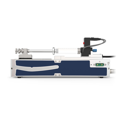
❷2 low pressure syringe pumps neMESYS 290 N
❸Bus termination plug
❹2 glass syringes
❺Power supply cable
❻USB-cable

CETONI System Hardware Manual 13
❼Interconnect cable
❽Windows PC (customer device - not part of the delivery scope)
CAUTION. Consider the reduced stability in the upright position and try to minimize
the risk of overturning and place the devices at least 40cm from the edge of the table.
IMPORTANT. Make sure that the ventilation slots which are present on some devices
do not get covered.

14 CETONI System Hardware Manual
3.2 Installing software
For installation, simply start the setup file of the QmixElements software on the enclosed CD.
When installing the software for the first time, make sure to also install the corresponding device
drivers.

CETONI System Hardware Manual 15
3.3 Connecting the base module
Connect the USB port of the base module (USB type B) to a free USB port of your PC (USB type A).
Connect the base module to a mains socket using the supplied power cable. The device can be operated
with alternating voltages of 90 to 264 V and 47 to 63Hz.
CAUTION. Risk of injury from damaged cables and plug devices. Inspect the unit and
lines for damage before starting the unit! Never operate the unit with damaged lines and
plugging devices! Only use cables from the scope of supply.
CAUTION. Danger of tripping over the power and connection cable. When laying
cables, ensure that any risk of stumbling is avoided!
Turn on the device with the mains switch in order to bring it into an operational condition. The power
switch should illuminate when the unit is turned on. If this is not the case, check that the power
connector cable is correctly plugged into both the unit and mains power supply.
USB-port (type B)
Mains connection
Fuse
Mains switch

16 CETONI System Hardware Manual
3.4 Creating a device configuration
(1) Please connect the base module to your PC as described in the previous section. Use the supplied
USB cable and the power cable.
(2) Start the software and click on Create Configuration ❶or select Device
Create Configuration
❷from the main menu.

CETONI System Hardware Manual 17
(3) Create a new device configuration setup like the physical device setup with the Device
Configurator by drag & drop. Simply drag and drop the individual devices from the device list into
the current configuration ❶ or add the devices by double-clicking on them. Please note, adding
the base module to your configuration is not necessary, that's why you won't find it within the
device list (except you own a Starter Module with integrated pump).
(4) Save this configuration by clicking on Save ❷ and continue by clicking on Configure ❸.
IMPORTANT. Please do not plug all modules of your setup together from the
beginning as it needs to be a step by step procedure. The software carefully guides you
through the configuration process of each single module on your screen.

18 CETONI System Hardware Manual
3.5 Configuring single modules
After clicking on Configure, the Configuration Wizard guides you through the configuration of all
modules. Simply follow the instructions on the screen ❶to configure each module one by one.
(1) Connect the first device to the base module according to the instructions in the software. Only
one device at a time may be connected to the base module for configuration. Make sure that the
base module is switched off when connecting and disconnecting modules.
HINT. For an easier mechanical handling you can use the interconnect cable ❷ for
creating connectivity between the base module and the device to be configured.
IMPORTANT. Make sure that the bus terminator plug ❸ is always plugged in before
the system is switched on, otherwise data communication may be disturbed.
(2) After successful configuration, disconnect the device you have just configured from the base
module
(3) Follow the instructions displayed on the screen as before.
(4) Repeat these steps for all other devices in this configuration.

CETONI System Hardware Manual 19
IMPORTANT. During configuration, connect only one single module at a time to the
base module to configure it in the software.
3.6 Assembling the complete system and
connecting it to the software
(1) After the successful software device configuration of all modules, you can connect the physical
devices all together to one whole setup now. To do this, place the module that you want to
connect next to your base module or your existing system so that the centering pins of the last
module of the system are opposite the centering holes of the module to be connected. Plug the
new module into the system. The centering pins are guided into the respective centering holes
and the connectors are connected with a contact fit. Connect the D-Sub connectors together
ensuring a secure contact. To ensure a proper contact between the modules, both modules must
lie flat against each other. Avoid tilting the modules.
(2) Plug the bus terminator plug into the socket of the last connected module of your system.

20 CETONI System Hardware Manual
(3) Follow the instructions of the Configuration Wizard and restart the software. Then establish a
connection between your configuration and the physical devices by clicking on the connector
icon (see figure below) in the user interface.
(4) Now your CETONI system is ready for use and you can explore the functions of the software.
IMPORTANT. Always plug the Bus-terminating-plug into the socket of the last
connected module. Otherwise disturbances to the data communication may occur.
IMPORTANT. The function of the devices was tested with water prior to the delivery.
Despite thorough cleaning minimal residues may remain in the system. If you have a
critical application, you should rinse your system before use.
Other manuals for BASE 120
2
This manual suits for next models
1
Table of contents
Other cetoni Laboratory Equipment manuals
Popular Laboratory Equipment manuals by other brands
Nanosonics
Nanosonics Trophon EPR user manual
Thermo Scientific
Thermo Scientific Accela Open Autosampler Hardware manual

World Precision Instruments
World Precision Instruments PUL-1000 instruction manual
Heidolph
Heidolph REAX 2 instruction manual
Adaltis
Adaltis NEXgen user manual
Hettich
Hettich MIKRO 200 operating instructions
IKA
IKA Mini MR standard operating instructions
caron
caron 6540 Operation manual
Sartorius
Sartorius Flexsafe Pro operating instructions

Leica
Leica EG F Instructions for use
TA Instruments
TA Instruments DISCOVERY XENON FLASH Getting started guide
Showa Denko
Showa Denko Shodex OHpak LB-800 Series Operation manual

