manuals.online logo
Brands
  1. Home
  2. •
  3. Brands
  4. •
  5. Manhattan Comfort
  6. •
  7. Indoor Furnishing
  8. •
  9. Manhattan Comfort Eiffel 251BMC6 User manual

Manhattan Comfort Eiffel 251BMC6 User manual

Ed. 001, 2022/06 - Manhattan Comfort.
888-230-2225
help@manhattancomfort.com
Model # 251BMC6, 251BMC8, 251BMC83, 251BMC84, 251BMC85
18
lb
11
lb
18
lb
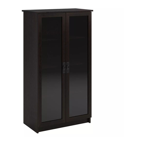
Eiffel 28.35 Floating Cabinet
2 Doors Floating Cabinet / Armoire flottante 2 portes
The indicated values consider static weights and evenly distributed over the parts.
Les valeurs indiquées tiennent compte des poids statiques et uniformément répartis sur les pièces.
n.° ID
2
01
02
03
04
05
2
2
2
1
1
06 1
07 1
04
INCLUDED IN THE PACKAGE / INCLUS DANS LE PACKAGE
Parts identification (Description) / Identification des pièces (Description) Quantity / Quantité
Top Panel and Base / Panneau du haut et Base
Back Panel / Panneau arrière
Side Panel / Panneau latéral
Left Door / Porte gauche
Right Door / Porte droite
REAR VIEW / VUE ARRIÈRE
FRONT VIEW / VUE DE FACE
FINAL APPEARANCE / APPARENCE FINALE
01
02
07
03
03
01
01
02
01
02
03
03
05
06
Shelf / Étagère
Plastic "H" Profile 665mm / Profilé en "H" en plastique 665mm
3
8x
A8x
B8x
C
!IMPORTANT! Two people are recommended to assemble and install this product.
The cabinet must be installed suspended and fixed to the wall (check the conditions of the wall to anchor the cabinet).
IMPORTANT! Deux personnes sont recommandées pour assembler et installer ce produit.
L'armoire doit être installée suspendue et fixée au mur (vérifier les conditions du mur pour ancrer l'armoire).
INCLUDED IN THE HARDWARE / INCLUS DANS LE MATÉRIEL
Simple hammer.
Marteau simple.
Manual screwdriver.
Tournevis manuel.
Electric drill and electric
screwdriver with drill
bit Ø1/2 inch and
phillips tips.
Perceuse électrique
et tournevis électrique
avec foret Ø1/2 pouce
et pointes phillips.
TOOLS NEEDED / OUTILS NÉCESSAIRES
Level indicator.
Indicateur de niveau.
28x
D4x
E4x
F
4x
G40x
H1x
I
1x
J8x
K2x
L
2x
M4x
N4x
O
4x
P
4
02
DETAIL 2 / DÉTAIL 2
0202
01
• Connect the Top Panel and Base (01) to
the Side Panels (02) with dowels (A) and
bolts (B).
At the end of the fixing, apply the
adhesive covers (C) on bolts (B).
Connectez les Panneau du haut et Base (01)
sur les Panneaux latéraux (02)des chevilles (A)
et des vis (B).
A la fin de la fixation, appliquez les couvercles
adhésifs (C) sur les vis (B).
Fixing the Back Panels (03):
IMPORTANT! The fixing the Back Panels (03) is optional.
The cabinet can be installed on the wall with or without
the back panels, according to the user's preference.
• Fix the Back Panels (03) by fitting the plastic profile (07) at the
junction between the two parts and applying the nails (D) in
the indicated positions.
STEP 2 / ÉTAPE 2
STEP 3 / ÉTAPE 3
Preparing the Side Panels (02):
• Fix the metal brackets (E) with bolts (H)
in the Side Panels (02), as shown in
the DETAIL 1 and DETAIL 2.
Préparation des Panneaux latéraux (02):
• Fixés les supports métalliques (E) avec
des vis (H) dans le Panneaux latéraux (02),
comme indiqué dans le DÉTAIL 1 et dans
le DÉTAIL 2.
STEP 1 / ÉTAPE 1 DETAIL 1 / DÉTAIL 1
01
02
REAR VIEW / VUE ARRIÈRE
07
03
03
01
02
!
Fixation des Panneaux arrière (03):
IMPORTANT! La fixation des Panneaux arrière (03) est
facultative. L'armoire peut être fixée au mur avec ou sans
les panneaux arrière, selon la préférence de l'utilisateur.
• Fixez le Panneaux arrière (03) en insérant le Profilé en plastique
(07) dans la couture entre les deux pièces et en appliquant les
clous (D) dans les positions indiquées.
!
01
02
DETAIL 3
DÉTAIL 3
Ø1/2 inch hole in the wall
Trou Ø1/2 pouce dans le mur
Kap Toggle bushing (O)
Douille Kap Toggle (O)
Bolt 1/4 x 2.1/4 inch
Vis 1/4 x 2,1/4 pouce
1/2 inch hole in the wall
for bushing and bolt (O).
Trou Ø1/2 pouce dans le
mur pour douille et vis (O).
Installing the cabinet on the wall:
• Place the already assembled cabinet on the desired
site for installation and mark the position for the
holes on the wall to fixation throught the four metal
brackets (E), as shown in the drawing and using
the brackets themselves as a reference.
• With electric drill and drill bit Ø1/2 inch, make the
four holes in the wall and apply the bushings (O).
• Replace the cabinet in the site and apply the bolts
1/4 x 2.1/4 inches as shown in the drawing, for
fixing the brackets (E) at the bushings (O) already
applied on the wall. At the end, apply the plastic
covers (F) over the brackets (E).
Installation du meuble au mur:
• Placez l'armoire déjà assemblée sur le site souhaité
pour l'installation et marquez la position des trous
sur le mur pour la fixation à travers les quatre
supports métalliques (E), comme indiqué sur le
dessin et en utilisant les supports eux-mêmes
comme référence.
• Avec une perceuse électrique et foret Ø1/2 pouce,
faites les quatre trous dans le mur et appliquez les
douilles (O).
• Replacez l'armoire sur le site et appliquez les vis
1/4 x 2,1/4 pouces comme indiqué sur le dessin,
pour la fixation des supports (E) dans les douilles
(O) déjà appliquées sur le mur. À la fin, appliquez
les couvercles en plastique (F) sur les supports (E).
FRONT VIEW / VUE DE FACE
ATTENTION! Before installing the cabinet, check
the conditions of the wall to anchor it and the
existence and posicion of hydraulic, electrical and
gas pipes, avoiding damage to these structures
when drilling the holes for the bushings and bolts.
The Kap Toggle bushings (O) supplied with the product
are for hollow walls or dry wall type. Check the type of
the wall on which the installation will be made and,
if necessary, look for more suitable fixing devices.
To mark the position and fix the cabinet on the
wall, check the level of the entire assembly and
the position of the feet in relation to the floor.
ATTENTION! Avant d'installer l'armoire, vérifiez
les conditions du mur pour l'ancrer ainsi que
l'existence et position des conduites hydrauliques,
électriques et de gaz, en évitant d'endommager
ces structures lors du perçage des trous pour les
douilles et les vis.
Les douilles Kap Toggle (O) fournies avec le produit
sont destinées à des cloisons creuses ou séches.
Vérifiez le type de mur sur lequel l'installation sera
effectuée et, si nécessaire, prévoir des dispositifs de
fixation les plus adaptés.
Pour marquer la position et fixer l'armoire au mur,
vérifiez le niveau de l'ensemble de l'assemblage
et la position des pieds par rapport au étage.
STEP 4 / ÉTAPE 4
5
06
DETAIL 4 / DÉTAIL 4
Preparing the Doors (05) and (06):
• Fix the hinges (G) with bolts (H) in the Doors (05)
and (06), as shown in the DETAIL 4.
• Fix the handle (M) in the Doors (05) and (06)
with bolts (N).
• Fix the metal plate (I) with bolts (K) in the
indicated position on the Left Door (05).
• Fix the lock (J) with bolts (K) in the Right Door (06).
Préparation des Portes (06) et (07):
• Fixez les charnières (G) avec les vis (H) dans les
Portes (05) et (06), comme indiqué dans le DÉTAIL 4.
• Fixez la poignée (M) dans les Portes (05) et (06)
avec des vis (N).
• Fixez la plaque métallique (I) avec les vis (K) dans
la position indiquée sur la Porte gauche (05).
• Fixez la serrure (J) avec les vis (K) dans la Porte
droite (06).
STEP 5 / ÉTAPE 5
05
01
02
01
02
02
Installing the Shelf (04):
• Insert the metal brackets (P) into the holes in the Side Panels (02)
and install the Shelf (04) over them.
• If you prefer, fix the Shelf (04) on the metal brackets (P) applying
the bolts (H), as shown in the DETAIL 5.
Installation de l'Étagère (04):
• Insérez les supports métalliques (P) dans les trous des Panneaux
latéraux (02) et installez l'Étagère (04) par-dessus.
• Si vous préférez, fixez l'Étagère (04) sur les supports métaliques (P)
en appliquant les vis (H), comme indiqué dans le DÉTAIL 5.
STEP 7 / ÉTAPE 7
STEP 6 / ÉTAPE 6
6
DETAIL 5 / DÉTAIL 5
02
04
01
01
02
04
Fixer and adjustment bolts.
Vis de fixation et réglage.
Installing the Doors (05) and (06):
• Fix the hinges connectors (G) of the Doors (05)
and (06) on the Side Panels (02) with bolts (H),
taking the markings in these Panels (02) as a
reference for correct positioning.
The hinge and its connector includes two more
bolts, shown in DETAIL 6. Use these fixer and
adjustment bolts to tighten, adjust and align
the doors.
• Fix the metal stopper (L) on the Base (01) with
bolts (K) so that both doors are aligned.
Installation des Portes (05) et (06):
• Fixez les connecteurs des charnières (G) des
Portes (05) et (06) sur les Panneaux latéraux
(02) avec des vis (H), en prenant les marques
comme référence pour un positionnement correct.
La charnière et son connecteur comprennent
deux autres vis, illustrées dans le DÉTAIL 6.
Utilisez ces vis de fixation et réglage pour serrer,
régler et aligner les portes.
• Fixez la butée métallique (L) à na Base (01)
avec des vis (K) afin que les deux portes
soient alignées.
DETAIL 6 / DÉTAIL 6
02
05
06
01
04
02
This manual suits for next models

4

Other Manhattan Comfort Indoor Furnishing manuals

Manhattan Comfort 10GMC1 User manual

Manhattan Comfort

Manhattan Comfort 10GMC1 User manual

Manhattan Comfort Bowery BC 80 User manual

Manhattan Comfort

Manhattan Comfort Bowery BC 80 User manual

Manhattan Comfort BE 941-205 User manual

Manhattan Comfort

Manhattan Comfort BE 941-205 User manual

Manhattan Comfort FORTRESS 3GMCF User manual

Manhattan Comfort

Manhattan Comfort FORTRESS 3GMCF User manual

Manhattan Comfort 9GMC1 User manual

Manhattan Comfort

Manhattan Comfort 9GMC1 User manual

Manhattan Comfort Tribeca Shoe Closet User manual

Manhattan Comfort

Manhattan Comfort Tribeca Shoe Closet User manual

Manhattan Comfort Eiffel 253BMC6 User manual

Manhattan Comfort

Manhattan Comfort Eiffel 253BMC6 User manual

Manhattan Comfort Liberty 62.99 User manual

Manhattan Comfort

Manhattan Comfort Liberty 62.99 User manual

Manhattan Comfort Hampton User manual

Manhattan Comfort

Manhattan Comfort Hampton User manual

Manhattan Comfort 88000 User manual

Manhattan Comfort

Manhattan Comfort 88000 User manual

Manhattan Comfort BPP 63-205 User manual

Manhattan Comfort

Manhattan Comfort BPP 63-205 User manual

Manhattan Comfort Rockefeller User manual

Manhattan Comfort

Manhattan Comfort Rockefeller User manual

Manhattan Comfort 222BMC1 User manual

Manhattan Comfort

Manhattan Comfort 222BMC1 User manual

Manhattan Comfort GRANVILLE DR-500 User manual

Manhattan Comfort

Manhattan Comfort GRANVILLE DR-500 User manual

Manhattan Comfort 34150 User manual

Manhattan Comfort

Manhattan Comfort 34150 User manual

Manhattan Comfort BL 03-06 User manual

Manhattan Comfort

Manhattan Comfort BL 03-06 User manual

Manhattan Comfort Liberty 202AMC6 User manual

Manhattan Comfort

Manhattan Comfort Liberty 202AMC6 User manual

Manhattan Comfort Libra Long Floating 45.35 Entertainment... User manual

Manhattan Comfort

Manhattan Comfort Libra Long Floating 45.35 Entertainment... User manual

Manhattan Comfort Mulberry 109GMC User manual

Manhattan Comfort

Manhattan Comfort Mulberry 109GMC User manual

Manhattan Comfort Bookcase 1.0 User manual

Manhattan Comfort

Manhattan Comfort Bookcase 1.0 User manual

Manhattan Comfort 14GMC1 User manual

Manhattan Comfort

Manhattan Comfort 14GMC1 User manual

Manhattan Comfort UTOPIA 53.14 User manual

Manhattan Comfort

Manhattan Comfort UTOPIA 53.14 User manual

Manhattan Comfort Amsterdam BPP 05-205 User manual

Manhattan Comfort

Manhattan Comfort Amsterdam BPP 05-205 User manual

Manhattan Comfort Liberty 2.0 204AMC6 User manual

Manhattan Comfort

Manhattan Comfort Liberty 2.0 204AMC6 User manual

Popular Indoor Furnishing manuals by other brands

Demco Sit-Stand Desktop Workstation Assembly instructions

Demco

Demco Sit-Stand Desktop Workstation Assembly instructions

Seville Classics UltraHD 20209 Assembly instructions

Seville Classics

Seville Classics UltraHD 20209 Assembly instructions

Jysk MARSTRAND 3600227 manual

Jysk

Jysk MARSTRAND 3600227 manual

Four Design FourCast 2 Line User information

Four Design

Four Design FourCast 2 Line User information

Home Decorators Collection Provence 9938800510 Assembly instructions

Home Decorators Collection

Home Decorators Collection Provence 9938800510 Assembly instructions

Velux VELUX INTEGRA Solar SST Directions for use

Velux

Velux VELUX INTEGRA Solar SST Directions for use

Blanco BLANCOPRECISION 157-061 Specification sheet

Blanco

Blanco BLANCOPRECISION 157-061 Specification sheet

Furniture of America YNJ-140-8 Assembly instructions

Furniture of America

Furniture of America YNJ-140-8 Assembly instructions

Seconique Furniture Tortilla Nest of 2 Tables Assembly instructions

Seconique Furniture

Seconique Furniture Tortilla Nest of 2 Tables Assembly instructions

Dorel Home Products DA2006379N manual

Dorel Home Products

Dorel Home Products DA2006379N manual

Furniture Tree CUBO CUB-CU412-FP Assembly instructions

Furniture Tree

Furniture Tree CUBO CUB-CU412-FP Assembly instructions

CONFORAMA Tresor Assembling instructions

CONFORAMA

CONFORAMA Tresor Assembling instructions

rizoma CIRCUIT 959 RS user manual

rizoma

rizoma CIRCUIT 959 RS user manual

Household Essentials 18400-1 instruction manual

Household Essentials

Household Essentials 18400-1 instruction manual

Songmics VASAGLE LTV097 manual

Songmics

Songmics VASAGLE LTV097 manual

Furniture of America YNJ-20601C35 Assembly instructions

Furniture of America

Furniture of America YNJ-20601C35 Assembly instructions

Amart Furniture ZAHRA 73201 Assembly instruction

Amart Furniture

Amart Furniture ZAHRA 73201 Assembly instruction

Rauch AC354.0FC3 Assembly instructions

Rauch

Rauch AC354.0FC3 Assembly instructions

manuals.online logo
manuals.online logoBrands
  • About & Mission
  • Contact us
  • Privacy Policy
  • Terms and Conditions

Copyright 2025 Manuals.Online. All Rights Reserved.