manuals.online logo
Brands
  1. Home
  2. •
  3. Brands
  4. •
  5. Manhattan Comfort
  6. •
  7. Indoor Furnishing
  8. •
  9. Manhattan Comfort Tribeca 53.54 Buffet User manual

Manhattan Comfort Tribeca 53.54 Buffet User manual

888-230-2225
help@manhattancomfort.com
Ed. 001, 2021/07 - Manhattan Comfort.
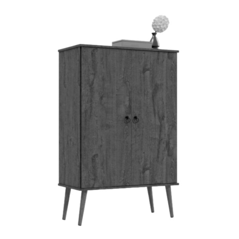
Tribeca 53.54 Buffet
Model # 244BMC12, 244BMC6, 244BMC62, 244BMC82, 244BMC9
11
lb
The indicated values consider static weights and evenly distributed over the parts.
Les valeurs indiquées tiennent compte des poids statiques et uniformément répartis sur les pièces.
11
lb 11
lb
6
lb
6
lb
11
lb
30
lb
2
n.° ID
REAR VIEW / VUE ARRIÈRE
FRONT VIEW / VUE DE FACE
FINAL APPEARANCE / APPARENCE FINALE
INCLUDED IN THE PACKAGE / INCLUS DANS LE PACKAGE
Quantity / Quantité
Parts Identification (Description) / Identification des pièces (Description)
2
1
1
1
1
1
1
1
1
1
1
4
2
2
1
1
1
1
1
2
1
1
Removable Shelf / Étagère amovible
Left Partition / Cloison gauche
Lower Back Panel / Panneau arrière inférieur
Left Side Panel / Panneau latéral gauche
Base / Base
Top Panel / Panneau du haut
Wooden Feet / Pieds en bois
Right Side Panel / Panneau latéral droit
Left Door / Porte gauche
Structural Bar for feet / Barre structurelle pour pieds
Handle / Poignée
Middle Crossbar / Traverse centrale
Right Partition / Cloison droite
Upper Rear Crossbar / Traverse arrière supérieure
Front of the drawer / Devant du tiroir
Left Side Panel of the drawer / Panneau latéral gauche du tiroir
Rear Panel of the drawer / Panneau arrière du tiroir
Base of the drawer / Base du tiroir
Right Door / Porte droite
Middle Door / Porte du milieu
Plastic "H" Profile 1325mm / Profilé en "H" en plastique 1325mm
Metallic slide 300mm for drawer (pair) / Glissière métallique 300mm pour tiroir (paire)
10
01
04
06
07
08
02
05
03
09
11
12
13
14
15
16
17
18
19
20
21
22
1
Upper Back Panel (with hole) / Panneau arrière supérieur (avec trou)
1
Right Side Panel of the drawer / Panneau latéral droit du tiroir
23
24
06
20
07
21
05
20
20
20
20
06
08
09
10
01
02
03
04
08
09
10
11
13
14
15
16
16
17
18
19
19
22
23
24
05
07
11
17
18
19 19
22
22
24
12
21
20
20
20
A30x
3
C4x D4x
E4x G8x H8x
B14x
I50x
F50x
K12x L8x
M4x
(main color / couleur principale)
N4x OP
Q4x R1x
INCLUDED IN THE HARDWARE / INCLUS DANS LE MATÉRIEL
J4x
6x
(main color / couleur principale)
4x
(feet color / couleur du pied)
S1x
T1x
!IMPORTANT! It is recommended to fix the cabinet on the wall with the anti-tipping bracket, to prevent accidental falls and damage.
IMPORTANT! Il est recommandé de fixer l'armoire au mur avec le support anti-basculement, pour éviter les chutes accidentelles et les dommages.
Manual screwdriver.
Tournevis manuel.
Simple hammer.
Marteau simple.
Electric drill and screwdriver with drill bit Ø10mm and phillips tips.
Perceuse et tournevis électrique avec foret Ø10mm et pointes phillips.
TOOLS NEEDED / OUTILS NÉCESSAIRES
Preparing the Feet (20) with
the Structural Bars (21):
• Fix the Feet (20) in the Structural Bars
(21) with dowels (A) and bolts (L).
• Fix the brackets (J) with bolts (K) in
the Structural Bars (21).
• Apply the adhesive covers (P) and the
protective felts (N) in the Feet (20).
Préparation des Pieds (20) avec les
Barres structureles (21):
• Fixez les Pieds (20) aux Barres
structuralles (21) avec des chevilles (A)
et des vis (L).
• Fixez les supports métalliques (J) avec
des vis (K) sur Barres structuralles (21).
• Appliquez les couvercles (P) et feutres
de protection (N) sur les Pieds (20).
4
21
20
20
21
20
20
Fixing the Base (08) on the Feet (20)
and on the Structural Bars (21):
• Fix the Base (08) on the Feet (20) with
bolts (L), as shown in the drawing.
• Apply the plastic cover (M) on bolts (L).
• Fix the Structural Bars (21) in the Base
(08) applying bolts (K) in the metal
brackets (J).
Fixation de la Base (08) sur les Pieds
(20) et les Barres structurelles (21):
• Fixez la Base (08) aux Pieds (20) avec
des vis (L), comme indiqué sur le dessin.
• Appliquez couvercles (M) sur les vis (L).
• Fixez les Barres structurelles (21) sous
la Base (08) en appliquant les vis (K) sur
les supports métalliques (J).
• Connect the Left Partition (02) and the
Right Partition (03) in the Middle Crossbar
(01) with the dowels Ø6 x 30mm (A) and
the bolts 5,0 x 50mm (B).
Connectez la Cloison gauche (02) et la
Cloison droite (03) à la Traverse centrale
(01) avec des chevilles Ø6 x 30mm (A) et
des vis 5.0 x 50mm (B).
08
21
20
20
21
STEP 1 / ÉTAPE 1
STEP 2 / ÉTAPE 2
STEP 3 / ÉTAPE 3
STEP 4 / ÉTAPE 4
20
20
02
01
03
02
01
04
05 03
06
• Fix the Top Panel (04) on the Partitions
(02) and (03) with dowels Ø6 x 30mm (A)
and cam lock hardware (C + D).
Fixez le Panneau du haut (04) sur les
Cloisons (02) et (03) avec les chevilles
Ø6 x 30mm (A) et du matériel de
verrouillage à came (C + D) .
• Fix the Left Side Panel (05) and the Right
Side Panel (06) in the Top Panel (04) with
dowels (A) and bolts 5.0 x 50mm (B).
Fixez le Panneau latéral gauche (05) et
le Panneau latéral droit (06) dans le
Panneau du haut (04) avec des chevilles
(A) et des vis 5.0 x 50mm (B).
• Fit the Upper Rear Crossbar (07) between
the Side Panels (05) and (06) and over the
Top Panel (04), as shown in the drawing, and
fix its ends in the Side Panels (05) and (06)
with the bolts 5.0 x 50mm (B). Then, fix the
Top Panel (04) to the Crossbar (07) applying
the indicated four bolts 3.5 x 35mm (E).
Monter la Traverse arrière supérieure (07)
entre les Panneaux latéraux (05) et (06) et sur
le Panneau du haut (04), comme indiqué sur le
dessin, et fixer ses extrémités aux Panneaux
latéraux (05) et (06) avec vis (B).
Ensuite, fixez le Panneaux supérieur (04) à la
Traverse (07) en appliquant les quatre vis
3,5 x 35mm (E) indiquées.
• Fix the Base (08) under the Partitions (02) and
(03) and the Side Panels (05) and (06) with
dowels (A) and bolts 5.0 x 50mm (B).
Fixez la Base (08) sous les Cloisons (02) et (03)
et sous les Panneaux latéraux (05) et (06) avec
les chevilles (A) et des vis 5,0 x 50mm (B).
5
STEP 5 / ÉTAPE 5
STEP 6 / ÉTAPE 6
STEP 7 / ÉTAPE 7
07
04
05
02
03
06
08
01
10
23
09
06
07
REAR VIEW / VUE ARRIÈRE
04
05
08
REAR VIEW / VUE ARRIÈRE
• Fix the Back Panels (09) and (10) by fitting the
plastic profile (23) at the junction between the
two parts and applying the nails (F) in the
indicated positions.
Fixez le Panneau arrière inférieur (09) et le
Panneau arrière supérieur (10) en insérant le
Profilé en plastique (23) dans la couture entre
les deux pièces et en appliquant les clous (F)
dans les positions indiquées.
Preparing the Drawer:
• Connect the parts (11), (12), and (13) with
the dowels (A) and cam lock hardware (C+D),
as shown in the DETAIL 1.
Apply the adhesive covers (O).
• Connect the parts (12), (13) and (14) with the
dowels (A) and bolts 5,0 x 50mm (B).
• Insert the Base of the drawer (15) into the
channel in the Side Panels (12) and (13) and
in the Front of the drawer (11), and fix it at the
lower edge of the Rear Panel of the drawer (14)
with nails (F).
Préparation du tiroir:
• Connectez les pièces (11), (12) et (13) avec
les chevilles (A) et le matériel de verrouillage à
came (C+D), comme indiqué dans le DÉTAIL 1.
Appliquez les couvercles adhésifs (O).
• Connectez les pièces (12), (13) et (14) avec
les chevilles (A) et des vis 5,0 x 50mm (B).
• Insérer la Base du tiroir (15) dans le canal
des Panneaux latéraux (12) et (13) et dans
la Devant du tiroir (11) et le fixer au du bord
inférieur du Panneau arrière du tiroir (14)
avec des clous (F).
11
12
13
14
15
24
DETAIL 1
DÉTAIL 1
11
12
Hole in the Upper Back Panel (10) for the anti-tipping bracket (S). See the STEP 9.
Trou dans le Panneau arrière supérieur (10) pour le support anti-basculement (S). Voir l'ÉTAPE 9.
DETAIL 2
DÉTAIL 2 Preparing the Doors (17), (18) e (19):
• Fix the hinges (H) with bolts 4.0 x 14 (I)
in the Doors (17), (18) and (19), as shown
in the DETAIL 2.
• Fix the handle (22) in the Doors (19) with
the bolts 3.5 x 25mm (Q).
Préparation des Portes (17), (18) et (19):
• Fixez les charnières (H) avec des vis
4.0 x 14mm (I) sur les Portes (17), (18) et
(19), comme indiqué dans le DÉTAIL 2.
• Fixez la poignée (22) dans les Portes (19)
avec les vis 3,5 x 25mm (Q).
6
STEP 8 / ÉTAPE 8
STEP 9 / ÉTAPE 9
17 19 19 18
• Fit the bracket (S) into the hole in the Upper Back Panel (10) and fix it with bolts (I) under the Top Panel (04), as shown in the DETAIL 3.
Insérez le support (S) dans le trou du Panneau arrière (10) et fixez-le avec les vis (I) sous le Panneau du haut (04), comme indiqué dans le DÉTAIL 3.
• Place the already assembled cabinet in the desired site for installation and mark the position of the hole on the wall to fixation throught the bracket (S), as
shown in the drawing and using the bracket itself as reference.
Placez l'armoire déjà assemblée dans l'emplacement souhaité pour l'installation et marquez la position du trou sur le mur pour la fixation à travers le
support (S), comme indiqué sur le dessin et en utilisant le support (S) lui-même comme référence.
• Move the cabinet away from the wall and, with a electric drill and drill bit Ø10mm, make the hole in the wall and apply the bushing (R), as in the DETAIL 4.
Éloignez le meuble du mur et, avec une perceuse électrique et un foret de Ø10mm, faites le trou denas le mur et appliquez la douille (R), comme indiqué
dans le DÉTAIL 4.
• Reposition the cabinet in the place and apply the bolt (T) to fix the bracket (S) at the bushing (R) already applied on the wall, as shown in the DETAIL 5.
Repositionnez l'armoire sur le site et appliquez la vis (T) pour fixer le support (S) à la douille (R) déjà appliquée sur le mur, comme indiqué dans le DÉTAIL 5.
Fixing the cabinet on the wall with the anti-tipping bracket (S): /
Fixation de l'armoire au mur avec le support anti-basculement (S):
ATTENTION! Before to make the installation, check the conditions of the wall to anchor the cabinet and the existence and position of hydraulic, electrical and
gas pipes, avoiding damage to these structures when drilling the hole for applying the bushing (R) and the bolt (T) to fix the anti-tipping bracket (S).
The bushing (R) supplied with the product is for hollow walls or dry wall type. Check the type of the wall on which the installation will be made and, if necessary, look for more
suitable devices. To mark position and fix the cabinet on the wall, check the level of the entire assembly and the position of the feet in relation to the floor.
ATTENTION! Avant l'installation, vérifiez les conditions du mur pour ancrage de l'armoire, ainsi que l'existence et la position des conduites hydrauliques,
électriques et de gaz, en évitant d'endommager ces structures lors du perçage du trou pour appliquer douille (R) et la vis (T) pour fixer le support
anti-basculement (S). La douille (R) fourni avec le produit est pour mur creux ou cloison sèche. Vérifiez le type du mur et, si nécessaire, prévoir accessoires plus adaptés.
Pour marquer la position et fixer l'armoire au mur, vérifiez le niveau de l'ensemble de l'assemblage et la position des pieds par rapport au étage.
Mark the position
to drill the wall.
Marquez la position
pour percer le mur.
DETAIL 3
DÉTAIL 3
10
04
Underside
Face inférieure
Inner face
Face intérieure
04
10
Ø10mm hole in the wall.
Trou Ø10mm dans le mur.
Underside
Face inférieure
Inner face
Face intérieure
10
09
07
04
05 06
Inner face
Face intérieure
Inner face
Face intérieure
02 03
01
08
DETAIL 4
DÉTAIL 4
DETAIL 5
DÉTAIL 5
22 22
• Apply the plastic supports (G) in the
Partitions (02) and (03) and in the Side
Panels (05) and (06) and install the
Removable Shelves (16) on them.
Appliquez les supports plastiques (G) sur
les Cloisons (02) et (03) et sur les
Panneaux latéraux (05) et (06) et installez
les Étagères amovibles (16) sur eux.
7
STEP 10 / ÉTAPE 10
STEP 11 / ÉTAPE 11
06
05
16
16
02
03
04
08
01
07
11
24
12
13
14
05
02
03
06
18
19
19
17
04
07
08
Fixer and adjustment bolts.
Vis de fixation et réglage.
Installing the Doors:
Attention to the position of each of the
doors (17), (18) and (19).
• Fix the hinge connectors of the Doors on the
Partitions (02) and (03) and on the Side
Panels (05) and (06) with bolts (I), taking the
markings on the parts (02), (03), (05) and
(06) as reference for the correct positioning.
The hinges and connectors includes more two
bolts, as shown in DETAIL 6. Use these fixer
and adjustment bolts to tighten, adjust and
align the doors.
Installation des Portes:
Faites attention à la position de chacun
des portes (17), (18) et (19).
• Fixez les connecteurs des charnières des
Portes sur les Cloisons (02) et (03) et sur
Panneaux latéraux (05) et (06) avec des
vis (I), en prenant les marques sur les pièces
(02), (03), (05) et (06) comme référence
pour un positionnement correct.
Les charnières et ses connecteurs
comprennent deux autres vis, illustrées
dans le DÉTAIL 6. Utilisez ces vis de fixation
et réglage pour serrer, régler et aligner les
portes.
Installing the drawer:
• Install the drawer, fitting it so that the
metallic slides slide smoothly.
Installation du tiroir:
• Installez le tiroir en le fixant de manière à
ce que les glissières métalliques coulissent
en douceur.

This manual suits for next models

5

Other Manhattan Comfort Indoor Furnishing manuals
Manhattan Comfort 10GMC1 User manual

Manhattan Comfort

Manhattan Comfort 10GMC1 User manual

Manhattan Comfort UTOPIA 53.14 User manual

Manhattan Comfort

Manhattan Comfort UTOPIA 53.14 User manual

Manhattan Comfort 82300 User manual

Manhattan Comfort

Manhattan Comfort 82300 User manual

Manhattan Comfort BPP 33-169 User manual

Manhattan Comfort

Manhattan Comfort BPP 33-169 User manual

Manhattan Comfort Rockefeller 1.0 Bookcase User manual

Manhattan Comfort

Manhattan Comfort Rockefeller 1.0 Bookcase User manual

Manhattan Comfort Gramercy User manual

Manhattan Comfort

Manhattan Comfort Gramercy User manual

Manhattan Comfort Eiffel 251BMC6 User manual

Manhattan Comfort

Manhattan Comfort Eiffel 251BMC6 User manual

Manhattan Comfort Viennese Sideboard User manual

Manhattan Comfort

Manhattan Comfort Viennese Sideboard User manual

Manhattan Comfort Mulberry 109GMC User manual

Manhattan Comfort

Manhattan Comfort Mulberry 109GMC User manual

Manhattan Comfort Liberty 200AMC6 User manual

Manhattan Comfort

Manhattan Comfort Liberty 200AMC6 User manual

Manhattan Comfort Accentuatios Boden 99AMC128 User manual

Manhattan Comfort

Manhattan Comfort Accentuatios Boden 99AMC128 User manual

Manhattan Comfort Granville 45.27 User manual

Manhattan Comfort

Manhattan Comfort Granville 45.27 User manual

Manhattan Comfort 15400 User manual

Manhattan Comfort

Manhattan Comfort 15400 User manual

Manhattan Comfort BST 08-06 User manual

Manhattan Comfort

Manhattan Comfort BST 08-06 User manual

Manhattan Comfort 2GMCC User manual

Manhattan Comfort

Manhattan Comfort 2GMCC User manual

Manhattan Comfort CABRINI THEATER PANEL 1.8 Quick start guide

Manhattan Comfort

Manhattan Comfort CABRINI THEATER PANEL 1.8 Quick start guide

Manhattan Comfort BR 51 User manual

Manhattan Comfort

Manhattan Comfort BR 51 User manual

Manhattan Comfort HOPKINS 2GLF User manual

Manhattan Comfort

Manhattan Comfort HOPKINS 2GLF User manual

Manhattan Comfort Rockefeller User manual

Manhattan Comfort

Manhattan Comfort Rockefeller User manual

Manhattan Comfort GRANVILLE DR-500 User manual

Manhattan Comfort

Manhattan Comfort GRANVILLE DR-500 User manual

Manhattan Comfort 222500 User manual

Manhattan Comfort

Manhattan Comfort 222500 User manual

Manhattan Comfort 200AMC6 User manual

Manhattan Comfort

Manhattan Comfort 200AMC6 User manual

Manhattan Comfort Bookcase 1.0 User manual

Manhattan Comfort

Manhattan Comfort Bookcase 1.0 User manual

Manhattan Comfort Viennese 100600 User manual

Manhattan Comfort

Manhattan Comfort Viennese 100600 User manual

Popular Indoor Furnishing manuals by other brands

Safavieh Furniture Arlo Mid Century DCH3002A-SET2 manual

Safavieh Furniture

Safavieh Furniture Arlo Mid Century DCH3002A-SET2 manual

AFi HB-POR Assembly instructions

AFi

AFi HB-POR Assembly instructions

American Standard Jefferson Mirror 9630.101 Specification sheet

American Standard

American Standard Jefferson Mirror 9630.101 Specification sheet

Bensons for Beds Sandra STK778201 Sandra STK778204 Assembly instructions

Bensons for Beds

Bensons for Beds Sandra STK778201 Sandra STK778204 Assembly instructions

AKANTE FASCINATION DT086 Assembly instructions

AKANTE

AKANTE FASCINATION DT086 Assembly instructions

PHI VILLA E02GF096 Use and care guide

PHI VILLA

PHI VILLA E02GF096 Use and care guide

Argos COT Assembly instructions

Argos

Argos COT Assembly instructions

Living Spaces LAKELAND DTLAKERT Assembly instruction

Living Spaces

Living Spaces LAKELAND DTLAKERT Assembly instruction

VITRA Comma manual

VITRA

VITRA Comma manual

Forte ZMBM01L-0002 Assembling Instruction

Forte

Forte ZMBM01L-0002 Assembling Instruction

NEXERa 115203 Assembly instructions

NEXERa

NEXERa 115203 Assembly instructions

Furniture of America Majken FOA4496E Assembly instructions

Furniture of America

Furniture of America Majken FOA4496E Assembly instructions

OSP Designs ALEXANDRIA ALX12 operating instructions

OSP Designs

OSP Designs ALEXANDRIA ALX12 operating instructions

beaux meubles BMU 58 Assembly instructions

beaux meubles

beaux meubles BMU 58 Assembly instructions

Seconique LUDLOW Assembly instructions

Seconique

Seconique LUDLOW Assembly instructions

heute wohnen 83120 Assembly instruction

heute wohnen

heute wohnen 83120 Assembly instruction

RECARO NECK REST operating instructions

RECARO

RECARO NECK REST operating instructions

dg casa 4 DRAWER TV STAND manual

dg casa

dg casa 4 DRAWER TV STAND manual

manuals.online logo
manuals.online logoBrands
  • About & Mission
  • Contact us
  • Privacy Policy
  • Terms and Conditions

Copyright 2025 Manuals.Online. All Rights Reserved.