manuals.online logo
Brands
  1. Home
  2. •
  3. Brands
  4. •
  5. Manhattan Comfort
  6. •
  7. Indoor Furnishing
  8. •
  9. Manhattan Comfort Baxter 62.99 User manual

Manhattan Comfort Baxter 62.99 User manual

Ed. 006, 2020/10 - Manhattan Comfort.
Model # 219BMC1, 219BMC12, 219BMC2, 219BMC21,
219BMC6, 219BMC8, 219BMC9, 219BMC94
888-230-2225
help@manhattancomfort.com
11
lb
11
lb
33
lb
8.8
lb
39
lb
2.2
lb
2.2
lb
11
lb 11
lb
Baxter 62.99
Freestanding / Agencement meuble TV
The indicated values consider static weights and evenly distributed over the parts.
Les valeurs indiquées tiennent compte des poids statiques et uniformément répartis sur les pièces.
2
01
22
02
03
04
05
07
07
08
09
10
07
12
13
14
11
15
06
07
08
04
15
12
13
14
16
17
18
19
20
21
06
22 22
22
23
24
1
1
1
1
1
1
1
1
4
1
1
1
1
1
2
1
1
1
1
1
1
1
1
1
10
01
04
06
07
08
02
05
03
09
11
12
13
14
Glass Shelf / Étagère en verre
Right Door / Porte droite
LED Light (batteries not included) / Luminaire LED (piles non incluses)
15
16
17
18
19
20
21
22
23
24
REAR VIEW / VUE ARRIÈRE
FRONT VIEW / VUE DE FACE
INCLUDED IN THE PACKAGE / INCLUS DANS LE PACKAGE
Hole for anti-tipping bracket /
Trou pour support anti-basculement
Holes to pass wires /
Trou pour passer les fils
n.° ID Parts Identification (Description) / Identification des pièces (Description) Quantity / Quantité
Left Partition / Cloison gauche
Middle Shelf / Étagère du milieu
Left Side Panel / Panneau latéral gauche
Middle Board / Planche du milieu
Right Partition / Cloison droite
Base / Base
Right Side Panel / Panneau latéral droit
Front Frame / Cadre de face
Rear Column / Colonne arrière
Lower Rear Bar / Barre arrière inférieure
Back Panel / Panneau arrière
Lower Panel / Panneau inférieur
Middle Panel / Panneau central
Upper Panel / Panneau supérieur
Upper Rear Bar / Barre arrière supérieure
Upper Shelf / Étagère supérieure
Left Side Panel of the cubby / Panneau latéral gauche du compartiment
Right Side Panel of the cubby / Panneau latéral droit du compartiment
Shelf of the cubby / Étagère du compartiment
Left Door / Porte gauche
Metallic Feet H150mm / Pieds métalliques H150mm
34x
A28x BC
D E F
8x
8x 8x 19x
3
GH I
8x 89x 50x
J K
16x 4x L4x
M N
30x 2x O2x
PQ
1x 1x R1x
!
IMPORTANT! Two people are needed to assemble this product.
It is recommended to fix the furniture to the wall with the anti-tipping bracket, to prevent accidental falls and damage.
IMPORTANT! Deux personnes sont nécessaires pour assembler ce produit.
Il est recommandé de fixer le meuble au mur avec le support anti-basculement, pour éviter les chutes accidentelles et
les dommages.
INCLUDED IN THE HARDWARE / INCLUS DANS LE MATÉRIEL
Simple hammer.
Marteau simple.
Manual screwdriver.
Tournevis manuel.
Electric drill and electric screwdriver with
drill bit Ø10mm and phillips tips.
Perceuse électrique et tournevis électrique avec
foret Ø10mm et pointes phillips.
TOOLS NEEDED / OUTILS NÉCESSAIRES
• Connect the Middle Shelf (03)
into Partitions (01) and (02)
with dowels (A) and bolts (B).
Connectez l'Étagère du milieu
(03) aux Cloisons (01) et (02)
avec les chevilles (A) et des
vis (B).
Preparing the Doors:
• Fix the hinges (L) in the
Doors (20) and (21) with
bolts (M), as shown in
the DETAIL 1.
Préparation des Portes:
• Fixez les charnières (L) aux
Portes (20) et (21) avec des
vis (M), comme indiqué dans
le DÉTAIL 1.
20
4
01
03
02
21
01
02
03
06
05
04
22
22
Lower face /
Face inférieure
DETAIL 2 (botton view - position of the feet) / DÉTAIL 2 (vue de dessous - position des pieds) • Connect the Base (04) to the Partitions (01) and
(02) and to the Side Panels (05) and (06) with
dowels (A) and bolts (B).
Connectez la Base (04) aux Cloisons (01) et (02)
et aux Panneaux latéraux (05) et (06) avec les
chevilles (A) et des vis (B).
• Fix the metallic feet (22) under the Base (04) with
bolts 4.5 x 16mm (J). Pay attention to the position
of the feet, as shown in the DETAIL 2.
Fixez les pieds métalliques (22) sous la Base (04)
avec les vis 4.5 x 16mm (J). Faites attention à la
position des pieds, comme indiqué en DÉTAIL 2.
• Apply adhesive felt to the lower end of the feet.
Appliquez le feutre adhésif sur le bas des pieds.
Adhesive protective felt /
Feltre protecteur adhésif
STEP 1 / ÉTAPE 1
STEP 2 / ÉTAPE 2
STEP 3 / ÉTAPE 3
DETAIL 1
DÉTAIL 1
5
DETAIL 3
DÉTAIL 3
Preparing/fixing the
Lower Panel (12) on
the Middle Board (08):
• Fix the Lower Panel (12)
on the Middle Board (08)
with dowels (A) and
bolts (B).
Préparation/fixation du
Panneau inférieur (12)
sur le Planche du
milieu (08):
• Fixez le Panneau inférieur
(12) sur la Planche du
milieu (08) avec des
chevilles (A) et des
vis (B).
12
08
01
02
04
05
06
03
07
07
22
22
22
22
12
08
Front face /
Face avant
• Connect the Middle Board (08) to the
Partitions (01) and (02) and to the
Side Panels (05) and (06) using dowels
(A) and cam lock hardware (C + D), as
shown in the DETAIL 3.
Connectez la Planche du milieu (08)
sur les Cloisons (01) et (02) et sur les
Panneaux latéraux (05) et (06) avec
des chevilles (A) et du matériel de
verrouillage à came (C + D), comme
indiqué dans le DÉTAIL 3.
Lower face /
Face inférieure
Rear face /
Face arrière
Lower face /
Face inférieure
• Fix the lower end of Rear Columns (07)
on the Base (04) with bolts (B).
Fixez l'extrémité inférieure des
Colonnes arrière (07) sur la Base (04)
avec les vis (B).
STEP 4 / ÉTAPE 4
STEP 5 / ÉTAPE 5
6
02
01
05
04
07
08
06
07
12
09
• Fit the Front Frame (09) under the Middle Board (08) and between
the Side Panels (05) and (06) and fix it in the Middle Board (08),
the Side Panels (05) and (06) and the Partitions (01) and (02) with
metal brackets (E) and bolts (H), as shown in the DETAIL 4.
Monter le Cadre de face (09) sous la Planche du milieu (08) et
entre les Panneaux latéraux (05) et (06) et le fixer à la Planche (08),
aux Panneaux latéraux (05) et (06) et aux Cloisons (01) et (02)
avec des supports métalliques (E) et des vis (H), comme indiqué
dans le DÉTAIL 4.
15.83in (402mm)
03
Preparing the anti-tipping bracket (P):
• Position the bracket (P) under and close to
the rear edge of the Middle Shelf (03) and
fix it with bolts (M), as shown in DETAIL 5.
Préparation du support anti-basculement (P):
• Positionnez le support (P) sous et près du bord
arrière de l'Étagère du milieu (03) et fixez-le avec
les vis (M), comme indiqué dans le DÉTAIL 5.
03
DETAIL 4 / DÉTAIL 4
STEP 6 / ÉTAPE 6
REAR VIEW
VUE ARRIÈRE
DETAIL 6 / DÉTAIL 6
DETAIL 5 / DÉTAIL 5
Fixing the Rear Columns (07) in the Side Panels (05) and (06):
• Fix the Rear Columns (07) in the Side Panels (05) and (06), applying the
steel plates (G) with bolts (H), as shown in DETAIL 6.
Fixation des Colonnes arrière (07) aux Panneaux latéraux (05) et (06):
• Fixez les Colonnes arrière (07) aux Panneaux latéraux (05) et (06) avec les tôles
d'acier (G) et les vis (H), comme indiqué dans le DÉTAIL 6.
7
15
08
06 11
12
07
10
05
12
13
14
04
01
02
10
03
05
07
07
• Fix the Lower Rear Bar (10) on the Partitions (01) and (02) with bolts (B); and in the Rear
Columns (07) with metal brackets (F) and bolts (H), as shown in the DETAIL 7.
Fixez la Barre arrière inférieure (10) sur les Cloisons (01) et (02) avec des vis (B); et dans
les Colonnes arrière (07) avec des supports métalliques (F) et des vis (H), comme indiqué
dans le DÉTAIL 7.
• Fix the Lower Panel (12) in the Rear Columns (07) with metal brackets (F) and bolts (H) .
Fixez le Panneau inférieur (12) aux Colonnes arrière (07) avec des supports métalliques (F)
et des vis (H).
• Place the Middle Panel (13) and Upper Panel (14), properly checking the arrangement of
each according to the holes and the drawing, and fix them to the Rear Columns (07) with
metal brackets (F) and bolts (H) .
Positionnez le Panneau central (13) et le Panneau supérieur (14), en vérifiant correctement
la disposition de chacun selon les trous et le dessin, et les fixer sur les Colonnes (07) avec
des supports (F) et des vis (H).
• Apply the steel plates (G) with bolts (H) at the junction of the Panels (12), (13) and (14) .
Appliquez tôles d'acier (G) avec vis (H) sur la jonction entre les Panneaux (12), (13) et (14).
• Fix the Upper Rear Bar (15) in the Upper Panel (14) and in the Rear Columns (07) with the
metal brackets (F) and bolts (H) .
Fixez la Barre arrière supérieure (15) au Panneau supérieur (14) et aux Colonnes (07) avec
des supports (F) et des vis (H).
• Fix the Back Panel (11) behind the Base (04), the Columns (07), the Lower Rear Bar (10)
and the Partitions (01) and (02) with nails (I) .
Fixez le Panneau arrière (11) derrière la Base (04), les Colonnes (07), la Barre arrière
inférieure (10) et les Cloisons (01) et (02) avec des clous (I).
DETAIL 7 / DÉTAIL 7
REAR VIEW
VUE ARRIÈRE
Hole for anti-tipping bracket
Trou pour support anti-basculement
Hole for passing wires
Trou pour passer les fils
Rear face /
Face arrière
Rear face /
Face arrière
Rear face /
Face arrière
STEP 7 / ÉTAPE 7
8
Installing the Doors (20) and (21):
• Fix the hinge connectors (L) of the Doors (20) and (21)
on the Left Side Panel (05) and on the Right Side Panel
(06) with bolts (M), taking the markings on the panels
(05) and (06) as reference for correct positioning.
The hinges and connectors includes two more bolts, as
shown in the DETAIL 8. Use these fixer and adjustment
bolts to tighten, adjust and align the doors.
Installation des Portes (20) et (21):
• Fixez les connecteurs des charnières (L) des Portes (20)
et (21) sur le Panneau latéral gauche (05)et sur le
Panneau latéral droit (06) avec des vis (M), en prenant
les marques comme référence pour un positionnement
correct . Le connecteur de charnière comprend deux vis,
illustrées dans le DÉTAIL 8. Utilisez la vis de fixation et
la vis de réglage pour serrer, régler et aligner la porte.
01
20
05
02
03
04
08
12
06
13
14
16
07
15
21
09
• Fix the Upper Shelf (16) in the Upper Panel (14)
with dowels (A) and bolts (B).
Fixez le Étagère supérieure (16) au Panneau
supérieur (14) avec des chevilles (A) et des vis (B).
DETAIL 8 / DÉTAIL 8
Fixer and adjustment bolts.
Vis de fixation et de réglage.
STEP 8 / ÉTAPE 8
9
DETAIL 9 / DÉTAIL 9
Bolt for fixing the glass.
Vis de fixation du verre.
12
14
08
17
18
19
17 18
19
23
16
04
13
01
03
20
21
06
24
09
15 17
23
22
22
• Fix the Side Panels (17) and (18)
of the cubby in the Panels (13)
and (14) and in the Upper Shelf
(16) with bolts (B).
Fixez les Panneaux latéraux des
compartiments (17) et (18) aux
Panneaux (13) et (14) et à la
Étagère supérieure (16) avec
des vis (B).
• Insert the Glass Shelf (23) in the
supports (K) and tighten the bolt
of each support for fixing the
glass (see DETAIL 9).
Insérez la Étagère en verre (23)
dans les supports (K) et serrez la
vis sur chaque support pour fixer
le verre (voir DÉTAIL 9).
• Install the LED light (24) under
the Upper Shelf (16) and between
the Side Panels (17) and (18) of
the cubby, following the
instructions on the luminaire's
own pack.
Installez le luminaire LED (24)
sous l'Étagère supérieure (16) et
entre les Panneaux latéraux du
compartiment (17) et (18), en
suivant les instructions de
l'emballage du luminaire lui-même.
• Insert the plastic covers (N) into
the holes in Panels (12) and (13).
Insérez les couvercles en plastique
(N) dans les trous des Panneaux
(12) et (13).
Preparing the upper cubby:
• Fix the metallic support for
glass (K) in the Side Panels (17)
and (18) with bolts (M).
• Fix the Side Panels (17) and (18)
in the Shelf (19) with dowels (A)
and bolts (B). At the end, apply
the adhesive covers (O).
Préparation du compartiment
supérieur:
• Fixez les supports métalliques pour
le verre (K) aux Panneaux latéraux
(17) et (18) avec des vis (M).
• Fixez les Panneaux latéraux (17) et
(18) à l'Étagère (19) avec des
chevilles (A) et des vis (B).
À la fin, appliquez les couvercles
adhésives (O).
STEP 9 / ÉTAPE 9
STEP 10 / ÉTAPE 10
10
DETAIL 10
DÉTAIL 10
11
Inner face
Face intérieure
03
Underside
Face inférieure
Ø10mm hole in the wall
Trou Ø10mm dans le mur
DETAIL 11
DÉTAIL 11
• Place the furniture next to the wall, in the desired location, and mark the position for the hole for the placement of the bushing (Q), using as reference
the metal bracket (P) already fixed under the Middle Shelf (03).
Positionnez l'armoire près du mur, à l'emplacement choisi, et marquez la position du trou pour placer la douille (Q), en utilisant comme référence le
support métallique (P) déjà fixé sur l'Étagère du milieu (03).
• After marking the position of the hole for the bushing (Q) on the wall, move the furniture away from the wall and with electric drill and drill bitØ10mm,
make the hole in the wall and apply the bushing (Q), as shown in the DETAIL 10.
Après avoir marqué la position du trou dans le mur, éloignez le meuble du mur et, avec une perceuse électrique avec un foret de Ø10mm, percez le trou
dans le mur et appliquez la douille (Q), comme indiqué dans le DÉTAIL 10.
• Reposition the furniture in the place and apply the bolt (R) to fixing the bracket (P) at the bushing (Q) applied on the wall, as shown in DETAIL 11.
Repositionnez le meuble en place et appliquez la vis (R) pour fixer le support (P) dans la douille (Q) appliquée au mur, comme indiqué dans le DÉTAIL 11.
STEP 11 / ÉTAPE 11
ATTENTION! Before to make the installation, check the conditions of the wall to anchor the furniture and the existence and position of hydraulic, electrical and
gas pipes, avoiding damage to these structures when drilling the hole for applying the bushing (Q) and bolt (R) to fix the anti-tipping bracket (P). The bushing (Q)
supplied with the product is for hollow walls or dry wall type. Check the type of the wall on which the installation will be made and, if necessary, look for more suitable devices.
ATTENTION! Avant l'installation, vérifiez l'état du mur pour ancrage de l'armoire, ainsi que l'existence et la position des conduites hydrauliques, électriques et
de gaz, en évitant d'endommager ces structures lors du forages des trous pour appliquer la douille (Q) et la vis (R) pour fixer le support anti-basculement (P).
La douille (Q) fourni avec le produit est pour mur creux ou cloison sèche. Vérifier le type de mur et, si nécessaire, prévoir des accessoires plus adaptés.
Fixing the furniture on the wall with the anti-tipping bracket (P)/
Fixation de l'armoire au mur avec le support anti-basculement (P):

This manual suits for next models

8

Other Manhattan Comfort Indoor Furnishing manuals
Manhattan Comfort Hampton User manual

Manhattan Comfort

Manhattan Comfort Hampton User manual

Manhattan Comfort 4GMCC User manual

Manhattan Comfort

Manhattan Comfort 4GMCC User manual
Manhattan Comfort 107GMC User manual

Manhattan Comfort

Manhattan Comfort 107GMC User manual
Manhattan Comfort BL 03-06 User manual

Manhattan Comfort

Manhattan Comfort BL 03-06 User manual

Manhattan Comfort 24900 User manual

Manhattan Comfort

Manhattan Comfort 24900 User manual

Manhattan Comfort BR 363 User manual

Manhattan Comfort

Manhattan Comfort BR 363 User manual
Manhattan Comfort BOWERY 55.12 User manual
Manhattan Comfort

Manhattan Comfort BOWERY 55.12 User manual

Manhattan Comfort Doris User manual

Manhattan Comfort

Manhattan Comfort Doris User manual
Manhattan Comfort 33AMC6 User manual

Manhattan Comfort

Manhattan Comfort 33AMC6 User manual
Manhattan Comfort BE 941-205 User manual
Manhattan Comfort

Manhattan Comfort BE 941-205 User manual

Manhattan Comfort BE 54 User manual

Manhattan Comfort

Manhattan Comfort BE 54 User manual
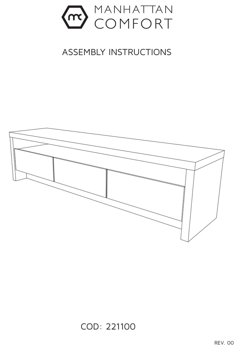
Manhattan Comfort 221100 User manual

Manhattan Comfort

Manhattan Comfort 221100 User manual
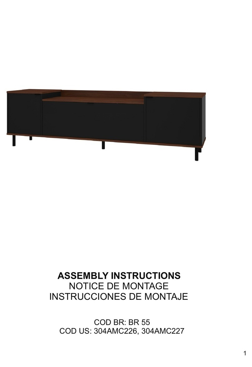
Manhattan Comfort Mosholu BR 55 User manual

Manhattan Comfort

Manhattan Comfort Mosholu BR 55 User manual

Manhattan Comfort 23700 User manual

Manhattan Comfort

Manhattan Comfort 23700 User manual

Manhattan Comfort Eiffel 35.43 Tall Cabinet User manual
Manhattan Comfort

Manhattan Comfort Eiffel 35.43 Tall Cabinet User manual

Manhattan Comfort Tribeca Shoe Closet User manual
Manhattan Comfort

Manhattan Comfort Tribeca Shoe Closet User manual

Manhattan Comfort Cooper BE 53 User manual

Manhattan Comfort

Manhattan Comfort Cooper BE 53 User manual

Manhattan Comfort Tribeca TV Panel User manual
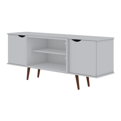
Manhattan Comfort

Manhattan Comfort Tribeca TV Panel User manual

Manhattan Comfort Hampton User manual

Manhattan Comfort

Manhattan Comfort Hampton User manual
Manhattan Comfort BR 51 User manual

Manhattan Comfort

Manhattan Comfort BR 51 User manual

Manhattan Comfort Liberty 70.86 Floating Entertainment Center User manual

Manhattan Comfort

Manhattan Comfort Liberty 70.86 Floating Entertainment Center User manual

Manhattan Comfort Eiffel 253BMC6 User manual

Manhattan Comfort

Manhattan Comfort Eiffel 253BMC6 User manual

Manhattan Comfort GRANVILLE DR-502 User manual

Manhattan Comfort

Manhattan Comfort GRANVILLE DR-502 User manual

Manhattan Comfort Libra 45.35 User manual

Manhattan Comfort

Manhattan Comfort Libra 45.35 User manual

Popular Indoor Furnishing manuals by other brands
Bell'O WAVS331 Assembly instructions

Bell'O

Bell'O WAVS331 Assembly instructions

Sauder Barrister Lane 414724 manual

Sauder

Sauder Barrister Lane 414724 manual

DRAGONN DN-CH-K01B instruction manual

DRAGONN

DRAGONN DN-CH-K01B instruction manual

Marta MT-2653 user manual

Marta

Marta MT-2653 user manual

Bush Business Furniture WC24578 manual

Bush Business Furniture

Bush Business Furniture WC24578 manual

Allied MDPED Assembly instructions

Allied

Allied MDPED Assembly instructions

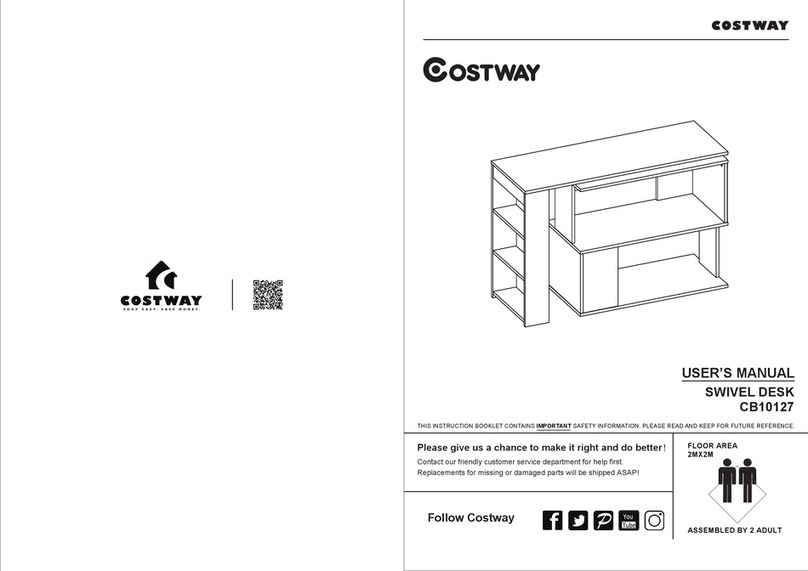
Costway CB10127 user manual

Costway

Costway CB10127 user manual

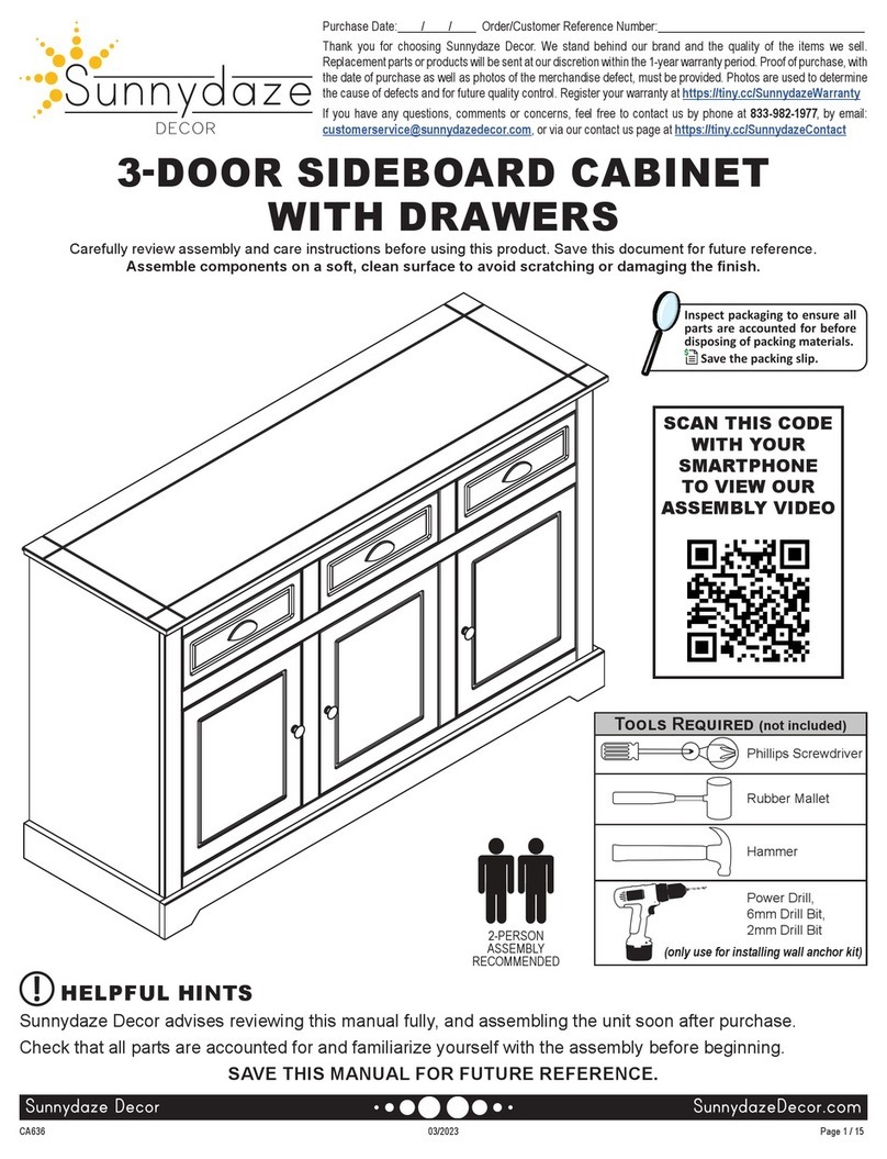
Sunnydaze Decor AGR-355 Assembly instructions

Sunnydaze Decor

Sunnydaze Decor AGR-355 Assembly instructions

Costway JV10516 manual

Costway

Costway JV10516 manual

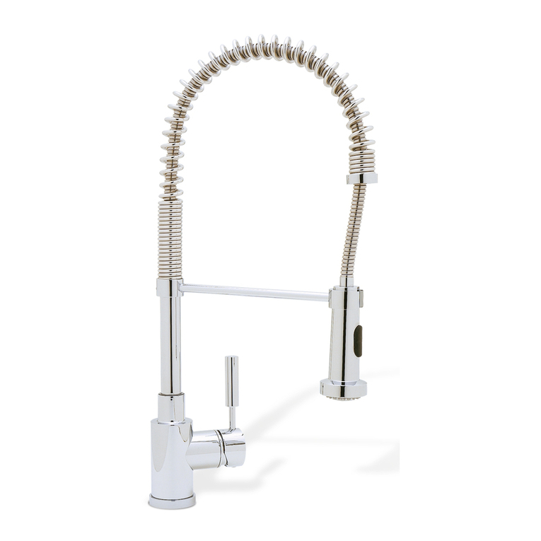
Blanco BLANCOMERIDIAN 157-140 Specification sheet

Blanco

Blanco BLANCOMERIDIAN 157-140 Specification sheet

Amart Furniture KLAUS 73591 Assembly instruction

Amart Furniture

Amart Furniture KLAUS 73591 Assembly instruction

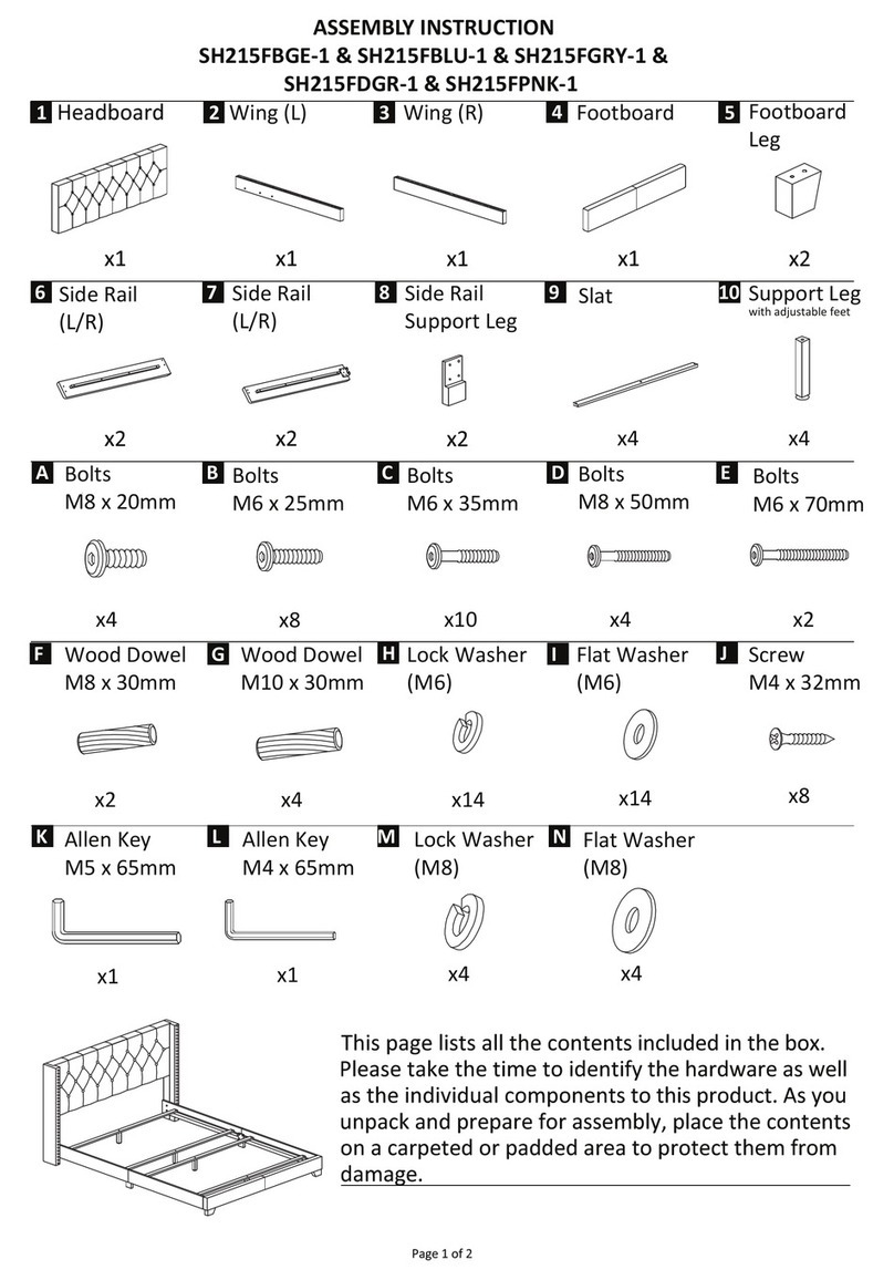
ROOMS TO GO SH215FBGE-1 Assembly instruction

ROOMS TO GO

ROOMS TO GO SH215FBGE-1 Assembly instruction

Whittier Wood 4651AFDHa Assembly instructions
Whittier Wood

Whittier Wood 4651AFDHa Assembly instructions

Wenger Trouper Upgrade instructions

Wenger

Wenger Trouper Upgrade instructions
ehleva NOVA Assembly instructions

ehleva

ehleva NOVA Assembly instructions

Interior Solutions DC2990 Operating and assembly instruction
Interior Solutions

Interior Solutions DC2990 Operating and assembly instruction

Forward Encounter - Storage Coffee Table Assembly instructions
Forward

Forward Encounter - Storage Coffee Table Assembly instructions

BENE STUDIO B297 Assembly instructions

BENE

BENE STUDIO B297 Assembly instructions

manuals.online logo
manuals.online logoBrands
  • About & Mission
  • Contact us
  • Privacy Policy
  • Terms and Conditions

Copyright 2025 Manuals.Online. All Rights Reserved.