Manitowoc Cleveland KET-3-T User manual

SE95004 Rev. 9
December 2012
Cleveland
™
Operators Manual
Electric Table Top Kettles
Installation & Operation
For units built after April 2010
1333 East 179t St., Cleveland, O io, U.S.A. 44110
P : 216.481.4900 Fx: 216.481.3782
www.clevelandrange.com
For your future reference.
Model # ______________________________________
Serial # _______________________________________
Read the manual thoroughly.
Improper installation, operation or
maintenance can cause property
damage, injury or death.
0
!
0
!
TABLE OF CONTENTS
For your safety . . . . . . . . . . . . . . . . . . . . . . . . . . . . . . . . . . . . . . . . . . . . . . 1-3
Installation . . . . . . . . . . . . . . . . . . . . . . . . . . . . . . . . . . . . . . . . . . . . . . . . . 3-5
Operating Instructions . . . . . . . . . . . . . . . . . . . . . . . . . . . . . . . . . . . . . . . . 6-7
Cleaning Instructions . . . . . . . . . . . . . . . . . . . . . . . . . . . . . . . . . . . . . . . . . . . 8
Preventative aintenance . . . . . . . . . . . . . . . . . . . . . . . . . . . . . . . . . . . . . . . 9
KET-3-T
KET-6-T
KET-12-T
KET-20-T
TKET-3-T
TKET-6-T
TKET-12-T
Done July 12
Model # & Serial #.

WARNING: Improper
installation, adjustment,
alteration, service or
maintenance can cause
property damage, injury or
death. Read the
installation and operating
instructions thoroughly
before installing or
servicing this equipment.
FOR YOUR SAFE Y
Do not store or use
gasoline or any other
flammable liquids and
vapours in the vicinity of
this or any other
appliance.
This appliance is not to be used by
persons with reduced physical,
sensory or mental capabilities, or lack
of experience and knowledge, unless
they have been given supervision or
instruction concerning use of the
appliance by a person responsible for
their safety.
This appliance is not for use by
children and they must be supervised
not to play with it.
Post in a prominent location,
instructions to be followed in the event
the user smells gas. This information
shall be obtained by consulting your
local gas supplier.
Do not obstruct the flow of combustion
and ventilation air.
Retain this manual for your reference.
FOR YOUR SAFETY
1.

0
0
0
0
0
0
0
0
0
0
0
0
0
0
Keep clear of pressure relief discharge.
Keep hands away from moving parts and pinch
points.
Surfaces and product may be hot! Wear protective
equipment.
Hot!
Do not climb, sit or stand on equipment.
Stand clear of product discharge path when
discharging hot product.
Do not lean on or place objects on kettle lip.
0
0
0
0
0
0
0
0
0
0
IMPORTANT
CAUTION / ATTENTION / PRECAUCIÓN
SERVICING / ENTRETIEN / SERVICIO
Hazard warnings are for your safey. Absence of a
warning does not mean the hazard is not present.
Unforeseen actions may result in unanticipated
hazards.
FOR YOUR SAFETY
0
!
0
0
0
0
Read the manual thoroughly. Improper installation,
operation or maintenance can cause property damage,
injury or death.
Inspect unit daily for proper operation.
Do not fill kettle above recommended level marked
on outside of kettle.
Floor may become slippery from product spillage.
Unit must be anchored as per manual.
Remove electrical power prior to servicing.
Ensure kettle is at room temperature and pressure
gauge is showing zero or less prior to removing any
fittings.
Have a qualified service technician maintain your
equipment.
2.

GENERA
Installation of the kettle must be accomplished by
qualified electrical installation personnel working to all
applicable local and national codes. Improper installation
of product could cause injury or damage.
This equipment is built to comply with applicable
standards for manufacturers. Included among those
approval agencies are: UL, NSF, ASME/Ntl. Bd., CSA,
C A, ETL, and others. Many local codes exist, and it is
the responsibility of the owner/installer to comply with
these codes.
RECEIVING INSPECTION
Before unpacking visually inspect the unit for evidence of
damage during shipping.
If damage is noticed, do not unpack the unit, follow
Shipping Damage Instructions shown below.
SHIPPING DAMAGE INSTRUCTIONS
If shipping damage to the unit is discovered or
suspected, observe the following guidelines in preparing
a shipping damage claim.
1. Write down a description of the damage or the reason
for suspecting damage as soon as it is discovered.
This will help in filling out the claim forms later.
2. As soon as damage is discovered or suspected, notify
the carrier that delivered the shipment.
3. Arrange for the carrier's representative to examine the
damage.
4. Fill out all carrier claims forms and have the examining
carrier sign and date each form.
UNCRATING
Caution:
Straps under tension and will snap when cut.
Carton may contain staples and Skid contains Nails.
Use proper safety equipment and precautions.
Unit is heavy use adequate help or lifting equipment as
needed.
INSTALLATION
MMooddeell // SSeerriiaall##
1x6
3.
1. Carefully cut any straps from container.
2. Lift off carton.
3. Inspect for hidden damage. If found refer to
“SHIPPIN DAMA E INSTRUCTIONS”.
4. Cut strap holding unit.
5.
Remove 1X6 holding unit in place.
6. Remove manual from kettle pot. Write down
the model
# and serial#
of the unit onto the front of this manual.
7. Lift kettle off skid and move kettle to its installation
location.
8. Discard packaging material according to local and or
state requirements.
Model # Unit Unit with
shipping box
KET3T 55 lbs. 95 lbs.
KET6T/ B 130 lbs. 170 lbs.
KET12T/ B 150 lbs. 190 lbs.
KET20T 220 lbs. 260 lbs.
TKET3T 95 lbs. 135 lbs.
TKET6T 186 lbs. 226 lbs.
TKET12T 275 lbs. 315 lbs.
APPROXIMATE WEIGHTS

POSITIONING
Units must be positioned on a firm, level stand that has been
bolted in place, or existing counter top, and bolted in place.
For mounting, these models are supplied with four threaded
bushings welded to the underside of the base.
The first installation step is to refer to the Specification
Sheets or Specification Drawings for detailed clearance
requirements and mounting hole locations of the kettle. If
you don’t have access to a specification sheet, check the
bottom of the kettle for location of threaded mounting
bushings.
CLEARANCE
REQUIREMENTS
* From back of mounting base.
Countertop Models
1. Drill mounting holes. If mounting to a Cleveland stand
holes are already predrilled.
2. Position the unit in its permanent location.
3. Once positioned permanently secure the unit to the
mounting surface with the hardware provided.
4. Seal around base of unit with silicone sealant.
5. Remove protective material covering stainless steel
surfaces.
KE -20- Leg ype Models
For floor type leg mount models position on a firm, level
sur face, level using adjustable feet and bolt two flanged
feet in place. Once the kettle is secure, screw tilt handle
into the threaded hole provided at the right of kettle.
E ECTRICA
ENSURE THE ELECTRICAL SUPPLY MATCHES THE
KETTLE'S REQUIREMENTS AS STATED ON THE
RATING LABEL.
Install in accordance with local codes and/or the National
Electric Code ANSI/NFPA No. 70 (USA) or the Canadian
Electric Code CSA Standard C22.2 (Canada). A separate
fused disconnect switch must be supplied and installed.
The kettle must be electrically grounded by the installer.
Model # Back* Left Right
Side Side
KET-3-T 000
KET-6-T 6” 00
KET-12-T 6” 00
KET-20-T 9” 00
TKET-3-T 7 1/8” 00
TKET-6-T 7 1/8” 00
TKET-12-T 9 7/8” 00
A wiring diagram is affixed to the underside of the console
cover.
Remove the four screws securing the console cover and
remove the cover. Using a water tight fitting feed
permanent copper wiring through the cut-out in the rear or
bottom of the console, and fasten to the three connection
terminal block, which is mounted on the top of the
console’s control panel. Be sure to connect the ground
wire to the separate ground terminal connector (ground
lug). Replace console cover and secure it with the four
screws.
The kettle is wired for 3-phase operation at the factory. For
single phase operation, rewire the terminal block to that
shown in the above diagram.
Note: Ensure main power is turned off before connecting
wires.
RED
YELLOW
BLACK
BLACK
BLUE
RED
L1 L2 L3
THREE
PHASE
RED
YELLOW
BLACK
BLACK
BLUE
RED
L1 L2
SINGLE
PHASE
ROUGE
JAUNE
NOIR
NOIR
BLEU
ROUGE
L1 L2 L3
TRI
PHASE
ROUGE
JAUNE
NOIR
NOIR
BLEU
ROUGE
L1 L2
MONO
PHASE
WATER FOR JACKET
The sealed jacket of the electric kettle is precharged with the
correct amount of a water based formula, and therefore, no
water connection is required to the kettle jacket.
FAUCET SPOUT
The kettle can be equipped with optional hot and/or cold water
faucet, requiring 1/2" copper tubing as supply lines. Mount
faucet bracket to the rear of the unt or studs provided.
Assemble faucet onto bracket and check for leaks.
POUR PATHS
Kettle Size Min. Max.
3 allon 15 1/2” 32”
6 allon 17 1/4” 36”
12 allon 18” 38”
20 allon 22” 45”
4.

INSTA ATION CHECKS
Although the kettle has been thoroughly tested before
leaving the factory, the installer is responsible for ensuring
the proper operation of kettle once installed.
Visual Checks
1.
Check unit is bolted in place.
1.
Check Marine Lock. See Marine Lock Testing
Procedure.
2. Check Tilting:
A/ Handle is in place and firmly tightened.
B/ Kettle tilts smoothly and freely.
3. Insure there are:
A/ Four screws securely holding the console cover.
B/
The bottom cover is in place and held with a nut.
Performance Checks
1. Supply power to the kettle by placing
the fused disconnect switch to the
"ON" position.
2. Before turning the kettle on, read the
Vacuum/Pressure auge. The
gauge's needle should be in the
green zone. If the needle is in the
"VENT AIR" zone, follow Kettle Venting Instructions.
3. Turn the kettle's ON/OFF Switch/Solid State Temperature
Control to "1" (Min.). The
Heat Indicator Light ( reen)
should remain lit, indicating the element is on, until the
set temperature is reached (130°F/54°C). Then the
green light will cycle on and off, indicating the element
is cycling on and off to maintain temperature.
4. Tilt the kettle forward. After a few seconds the
Low
Water Indicator Light (Red)
should be lit when the kettle
is in a tilted position. This light indicates that the element
has automatically been shut off by the kettle's safety
circuit. This is a normal condition when the kettle is in a
tilted position.
5. Raise the kettle to the upright position. The
Low Water
Indicator Light (Red)
should go out when the kettle is
upright.
6. Turn the ON/OFF Switch/Solid State Temperature Control
to "10" (Max.) and allow the kettle to preheat. The green
light should remain on until the set temperature
(260°F/127°C) is reached. Then the green light will cycle
ON and OFF, indicating the element is cycling ON and
OFF to maintain temperature. Fill the kettle with cold
water to the steam jacket’s welded seam. Refer to the
Temperature Range Chart for the time required to bring
the water to a boil.
7. When all testing is complete, empty the kettle and turn
the
ON/OFF Switch/Solid State Temperature Control
to
the “OFF” position.
C EANING
After installation the kettle must be thoroughly cleaned
and sanitized prior to cooking. See Cleaning Instructions.
50
0
100
150 200
250
300
350
400
40
50
60
0
10
20 30
psi kPa
V
E
N
T
A
I
R
50
0
100
150 200
250
300
350
400
40
50
60
0
10
20 30
psi kPa
V
E
N
T
A
I
R
50
0
100
150 200
250
300
350
400
40
50
60
0
10
20 30
psi kPa
V
E
N
T
A
I
R
5.

5
6
4
3
2
1
7
OPERATING INSTRUCTIONS
ITEM # DESCRIPTION
1. ilting Handle - Used for tilting the kettle.
2. Vacuum/Pressure Gauge - Indicate steam pressure in PSI inside steam jacket as well as vacuum in
inches of mercury.
3. Pressure Relief Valve (not shown) - This valve is used to vent the kettle and in the unlikely event there is
an excess steam build-up in the jacket, this valve opens automatically to relieve this pressure.
4. On-Off Switch/Solid State emperature Control - Turns kettle ON/OFF and allows the operator to adjust
the kettle temperature in increments from 1 (Min.) to 10 (Max.). (see Temperature Range Chart in the
Operating Instructions section).
5. Heat Indicator Light ( reen) - When lit, indicates that the kettle element is on. Cycles ON-OFF with
element.
6. Low Water Indicator Light (Red) - When lit, indicates that the kettle is low on water and will not operate in
this condition. This will also light when the kettle is tilted.
7. Marine Lock - Prevents unit from accidental tilting.
6.

OPERATING
THE KETT E
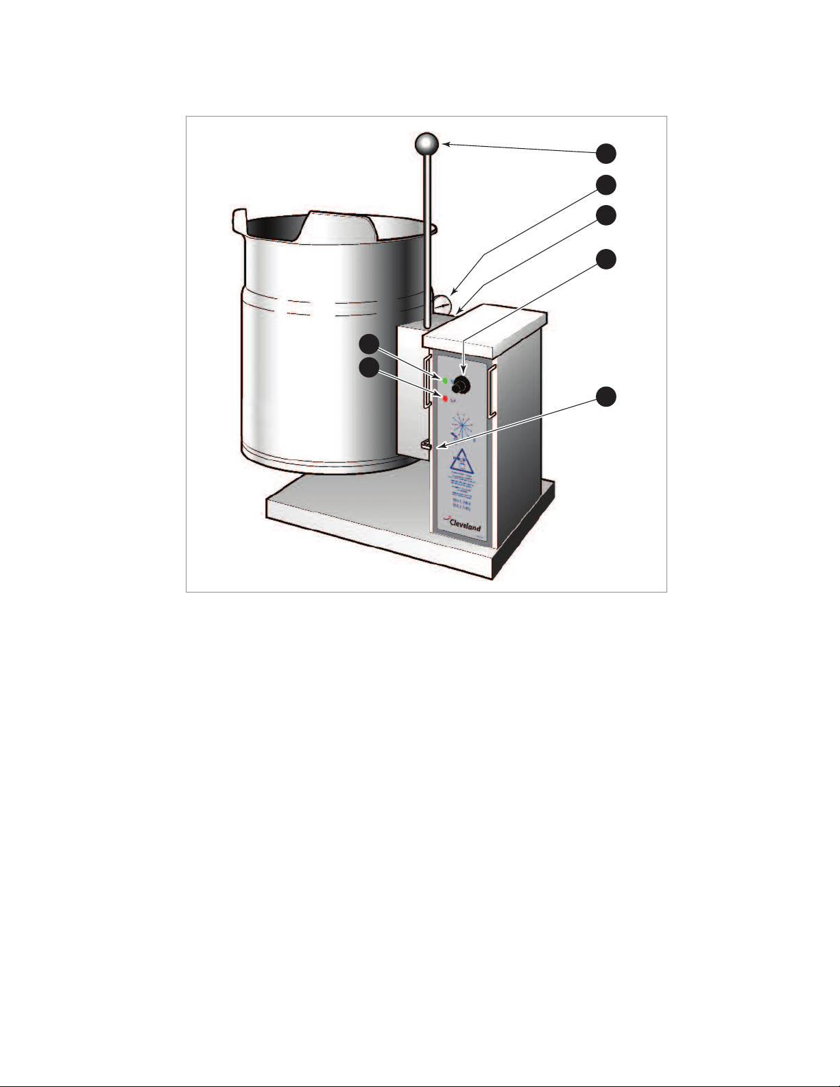
1. Before turning kettle on, read the Vacuum/Pressure
auge. The gauges needle should be in the green
zone. Once heated, the kettle's normal maximum
operating pressure is approximately 10-12 psi,
while cooking a water base product.
2. Ensure that the electrical service to the kettle is
turned on at the fused disconnect switch.
Temperature Range Chart
3. Preheat the kettle by turning the ON/OFF
Switch/Solid State Temperature Control to the
desired temperature setting (see above
"Temperature Range Chart"). The Heat Indicator
Light ( reen) will remain lit, indicating the burner is
lit, until the temperature setting is reached. When
the green light goes off, the heaters are off, and
preheating is complete.
NOTE: When cooking egg and milk products, the kettle
should not be preheated, as products of this nature
adhere to hot cooking surfaces. These types of food
should be placed in the kettle before heating is begun.
4. Place food product into the kettle. The Heat
Indicator Light ( reen) will cycle on and off
indicating the elements are cycling on and off to
maintain the set temperature.
NOTE: Do not fill kettle above
recommended level marked on
outside of kettle.
NOTE: The Low Water Indicator Light (Red) should
not be lit when kettle is in upright position during
operation. This light indicates that the elements
have been automatically shut off by the kettle's
safety circuit. It is, however, normal for the red light
to come on when the kettle is in a tilted position.
5. When cooking is completed place ON/OFF
Switch/Solid State Temperature Control to the
"OFF' position.
6. Pour the contents of the kettle into an
appropriate container by tilting the kettle
forward. Care should be taken to pour slowly
enough to avoid splashing off the product.
NOTE: As with cleaning food soil from any cookware,
an important part of kettle cleaning is to prevent food
from drying on. For this reason, cleaning should be
completed immediately after cooked foods are
removed.
APPROXIMATE BOI ING TIMES
Approximate Boiling Times
The accompanying chart shows approximate times
required for electric kettles of various capacities to boil
water. The ON/OFF Switch/Solid State Temperature
Control must be set at "10" (Max.) throughout the heatup
period. Water will boil about 1/3 faster if the kettle is
filled only to the outer steam jacket's welded seam,
resulting in a kettle filled to 2/3 capacity.
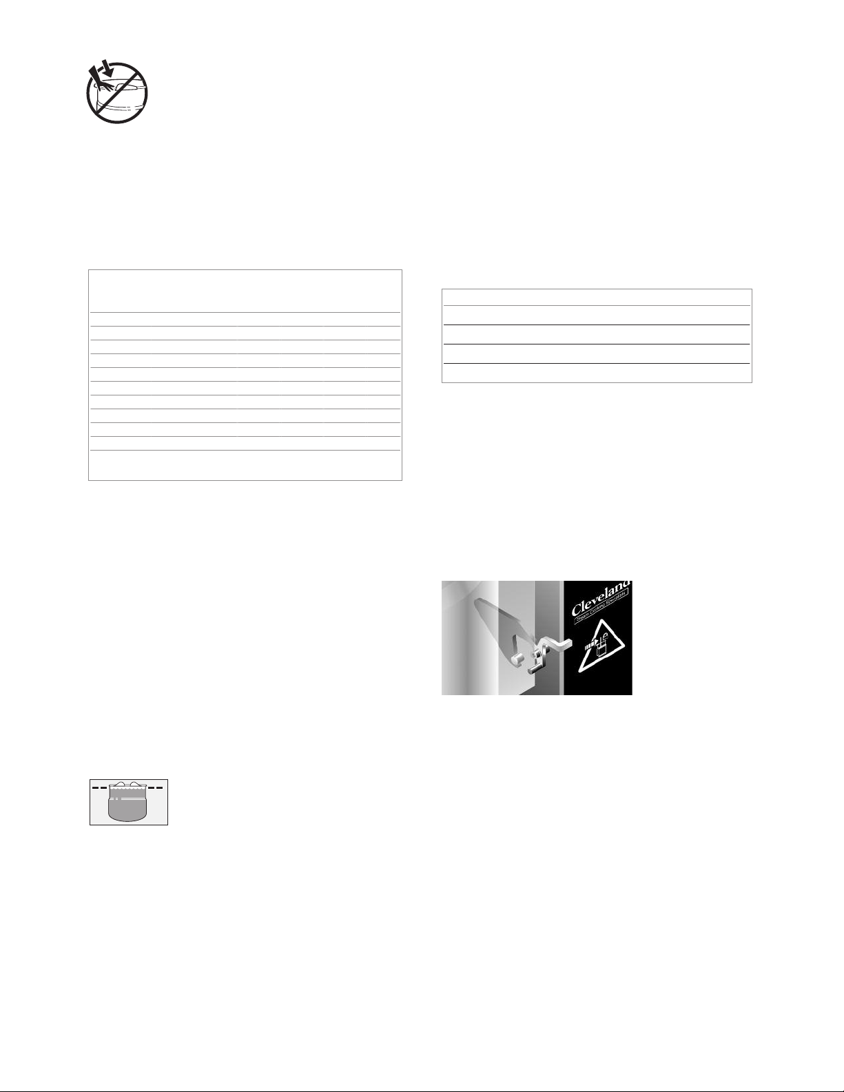
MARINE OCK
Your unit is equipped with a marine lock to prevent
accidental tilting. The following procedure should be
used to tilt the kettle.
1.
rasp the tilt handle.
2.
Hold the latch down to unlock tilting mechanism.
3.
Pull the handle to tilt kettle.
4.
To lock, return the kettle to its upright position and
push handle back.
NOTE: Inspect lock daily to ensure it is free moving and
does not bind or stick. Clean lock if necessary (see
Cleaning Instructions for details
Kettle Capacity Minutes
3 gallon/11 litre 15
6 gallon/23 litre 20
12 gallon/45 litre 25
20 gallon/80 litre 40
Temperature Approximate
Control Product Temperature
Setting °F °C
1. (Min.) 130 54
2. 145 63
3. 160 71
4. 170 77
5. 185 85
6. 195 91
7. 210 99
8. 230 110
9. 245 118
10. (Max.) 260 127
NOTE: Certain combinations of ingredients will
result in temperature variations
0
0
7.

CARE AND C EANING
Cooking equipment must be cleaned
regularly to maintain its fast, efficient
cooking performance and to ensure its
continued safe, reliable operation. The
best time to clean is shortly after each
use (allow unit to cool to a safe
temperature).
WARNINGS
Do not use
detergents or
cleansers that are
chloride based or
contain quaternary
salt.
Unit should never be
cleaned with a high
pressure spray hose.
Steel wool should
never be used for
cleaning the stainless
steel.
Do not leave water
sitting in unit when
not in use.
Do not use a metal
bristle brush or
scraper.
CLEANING INSTRUCTIONS
C EANING INSTRUCTIONS
1. Turn unit off.
2. Remove drain screen (if applicable). Thoroughly wash and rinse the screen
either in a sink or a dishwasher.
3. Prepare a warm water and mild detergent solution in the unit.
4. Remove food soil using a nylon brush.
5. Loosen food which is stuck by allowing it to soak at a low temperature
setting.
6. Drain unit.
7. Rinse interior thoroughly.
8.
Using mild soapy water and a damp sponge, wash the exterior, rinse, and dry.
NOTES
➩For more difficult cleaning applications one of the following can be used:
alcohol, baking soda, vinegar, or a solution of ammonia in water.
➩Leave the cover off when the kettle is not in use.
➩For more detailed instructions refer to Stainless Steel Equipment Care and
Cleaning (www.nafem.org/resources/stainlesssteelfinal.doc) on Nafem’s
website (www.nafem.org).
Chloride Cleaners
Wire Brush &
Scrapers
Steel Pads
High Pressure
Spray Hose
Stagnant
Water
0
0
0
0
8.

DAI Y
PRE-STARTUP
INSPECTION
1. Kettle tilts smoothly.
2. Pressure auge (E) is in the green when unit is cold.
3. reen Light (F) comes on when unit is energized.
4. Red Light (G) comes on when unit is tilted (tilting models only).
PREVENTATIVE MAINTENANCE
FOR MAIN ENANCE AND REPAIRS CON AC YOUR
AU HORIZED MANI OWOC SERVICE AGENCY AND HAVE A
QUALIFIED SERVICE ECHNICIAN MAIN AIN YOUR EQUIPMEN .
Shut off power at main
fuse disconnect prior
to servicing.
Ensure kettle is at room
temperature and pressure
gauge is showing zero or less
prior to removing any fittings.
Inspect unit daily for
proper operation.
0
Shut off power at main
fuse disconnect prior
to servicing.
Ensure kettle is at room temperature
and pressure gauge is showing zero
or less prior to removing any fittings.
0
Do not fill kettle above
recommended level
marked on outside of kettle.
Surfaces may be
extremely hot! Use
protective equipment.
Keep
appliance
and area
free and
clear of
combustibles.
Unit exhaust
contains carbon
monoxide.
Operate only
under a properly
functioning hood
with adequate
makeup air.
Stand clear of product
discharge path when
discharging hot product.
Wear protective equipment
when discharging hot product.
Do not lean on or place
objects on kettle lip.
Do not
attempt to
operate this
appliance
during a
power
failure.
Keep clear of pressure
relief discharge.
Keep hands away from
moving parts and pinch points.
For your safety
SERVICING
IMPORTANT
CAUTION
DANGER
GAS APPLIANCES
0
0
0
0
0
!
0
!
SIX MONTH SERVICE INSPECTION
1. Perform daily startup inspection.
2. rease bearings on both trunnions.
3. Fasteners securing panels are in place and tight.
4. Perform pressure relief valve periodic test (see PRESSURE RELIEF VALVE TESTIN ).
5. Insure there are four screws firmly holding down the cover. If not replace screws and/or missing or worn
nylon anchor nuts.
6. Check the bottom cover gasket is in place and not cracked.
7. Unit is bolted in place.
YEAR Y SERVICE INSPECTION
1. Perform six month service inspection.
2. Check kettle maximum temperature setting (see CALIBRATIN PROCEDURE).
3. Perform safety inspection using SAFETY INSPECITON CHECKLIST found in the MAINTENANCE
PROCEDURES.
9.
Refer to maintenance procedures and parts list manual
for detailed maintenance and testing instructions.
This manual suits for next models
6
Table of contents
Other Manitowoc Commercial Food Equipment manuals

Manitowoc
Manitowoc Delfield 18600 Series User manual

Manitowoc
Manitowoc K00497 User manual

Manitowoc
Manitowoc Garland Induction Designer Series User manual

Manitowoc
Manitowoc Frymaster FilterQuick FQE30 User manual

Manitowoc
Manitowoc U65 User manual

Manitowoc
Manitowoc LuminIce User manual

Manitowoc
Manitowoc Delfield N8100B User manual