Manitowoc Delfield 18600 Series User manual

18600 Series and CTP-NB
Service and Installation Manual
Please read this manual completely before attempting to install or operate this equipment! Notify carrier of damage! Inspect all
components immediately.
CTP-NB
Countertop Condiment Rail
18600PTBM
Pizza Tables with Raised Rail 18600BUCM
Work Tables
February 2013
Important Information
Read Before Use
Please Save These Instructions!
CAUTION
18600PTL
Pizza Tables with LiquiTec® Rail
18600BSTM
Work Table with Backsplash
18600PDL
Dual LiquiTec® Rail Prep Table

18600 and CTP-NB Series Service and Installation Manual
For customer service, call (800) 733-8829, (800) 773-8821, Fax (989) 773-3210, www.delfield.com
2
WARNING Read This Manual Thoroughly Before Operating, Installing, Or Performing Maintenance On The Equipment.
WARNING Failure To Follow Instructions In This Manual Can Cause Property Damage, Injury Or Death.
WARNING Do Not Store Or Use Gasoline Or Other Flammable Vapors Or Liquids In The Vicinity Of This Or Any Other
Appliance.
WARNING Unless All Cover And Access Panels Are In Place And Properly Secured, Do Not Operate This Equipment.
WARNING This Appliance Is Not Intended For Use By Persons Who Lack Experience Or Knowledge, Unless They Have
Been Given Supervision Or Instruction Concerning Use Of The Appliance By A Person Responsible For Their
Safety.
WARNING This Appliance Is Not To Be Played With.
WARNING Do Not Clean With Water Jet.
WARNING Do Not Use Electrical Appliances Inside The Food Storage Compartment Of This Appliance.
CAUTION Observe the following:
• Minimum clearances must be maintained from all walls and combustible materials.
• Keep the equipment area free and clear of combustible material.
• Allow adequate clearance for air openings.
• Operate equipment only on the type of electricity indicated on the specification plate.
• Unplug the unit before making any repairs.
• Retain this manual for future reference.
Important Warning And Safety Information

18600 and CTP-NB Series Service and Installation Manual
3
For customer service, call (800) 733-8829, (800) 773-8821, Fax (989) 773-3210, www.delfield.com
Receiving & Inspecting Equipment ...........................................3
Serial Number Information ........................................................4
Warranty Information.................................................................4
Regulatory Certifications............................................................ 4
Specifications.............................................................................5
Refrigerant Charges ...................................................................6
Installation .................................................................................6
Operation
18600PTBM & PTL Series......................................................7
18600BUCM & BSTM Series.................................................. 7
18600PDL Series....................................................................8
CTP-NB Series ........................................................................8
Pressure Control Settings..........................................................9
Temperature Control Settings....................................................9
Care And Cleaning...............................................................10-11
Wiring Diagram
18600PTBM & PTL Series....................................................12
18600BUCM & BSTM Series................................................13
18600PDL .............................................................................13
CTP-NB Series ......................................................................14
Replacement Parts..............................................................15-24
Standard Labor Guidelines ......................................................25
Notes ...................................................................................26-27
Contents
Receiving And Inspecting The Equipment
Even though most equipment is shipped crated, care should be
taken during unloading so the equipment is not damaged while
being moved into the building.
1. Visually inspect the exterior of the package and skid or
container. Any damage should be noted and reported to
the delivering carrier immediately.
2. If damaged, open and inspect the contents with the
carrier.
3. In the event that the exterior is not damaged, yet upon
opening, there is concealed damage to the equipment
notify the carrier. Notification should be made verbally as
well as in written form.
4. Request an inspection by the shipping company of the
damaged equipment. This should be done within 10 days
from receipt of the equipment.
5. Check the lower portion of the unit to be sure legs or
casters are not bent.
6. Also open the compressor compartment housing and
visually inspect the refrigeration package. Be sure lines
are secure and base is still intact.
7. Freight carriers can supply the necessary damage forms
upon request.
8. Retain all crating material until an inspection has been
made or waived.
Uncrating the Equipment
First cut and remove the banding from around the crate.
Remove the front of the crate material, use of some tools will
be required. If the unit is on legs remove the top of the crate
and lift the unit off the skid. If the unit is on casters it can be
"rolled" off the skid.

18600 and CTP-NB Series Service and Installation Manual
For customer service, call (800) 733-8829, (800) 773-8821, Fax (989) 773-3210, www.delfield.com
4
The serial number on 18600 Series units is located on the
electrical specifications tag affixed inside the compressor
section next to the pressure control.
The serial number on CTP-NB Series units is located on the
front of the unit.
Always have the serial number of your unit available when
calling for parts or service.
Warranty may be deemed invalid if other than
authorized OEM (original equipment manufacture)
replacement parts are used in Delfield equipment.
©2013 The Delfield Company. All rights reserved. Reproduction without
written permission is prohibited. “Delfield” is a registered trademark of The
Delfield Company.
Serial Number Information
Regulatory Certifications
Warranty Information
Visit http://www.delfield.com/minisite/service/warranty_info to:
• Register your product for warranty.
• Verify warranty information.
• View and download a copy of your warranty.
Models are certified by:
National Sanitation Foundation (NSF)
Underwriters Laboratories (UL)
Underwriters Laboratories of Canada (ULC)

18600 and CTP-NB Series Service and Installation Manual
5
For customer service, call (800) 733-8829, (800) 773-8821, Fax (989) 773-3210, www.delfield.com
Specifications
18600PTBM Pizza tables with raised rail
Model
1/3 Pan Size
Capacity # Of Doors
# Of
Shelves
Shelf Max
Load (LBS)
Shelf Area
FT2Volume
FT3BTU Load
Base/Rail
BTU Sys. Cap.
Base/Rail H.P.
Voltz/Hertz/
Phase Amps
NEMA
Plug
Ship Weight
LBS/KG
18648PTBM 6 (1) 27” 1 124 3.95 10.23 470/441 2001/952 1/4 115/60/1 10.0 5-15P 520/236
18660PTBM 7 19” & 27” 2 70/124 6.51 15.12 694/617 2409/1208 1/3 115/60/1 12.0 5-15P 575/260
18672PTBM 9 (2) 27” 2 124 7.9 18.10 776/794 2967/1587 1/2 115/60/1 14.0 5-20P 635/288
18691PTBM 11 (2)27” & (1) 19” 3 124/70 10.29 24.48 1062/1058 3537/1865 1/2 115/60/1 14.0 5-20P 770/350
18699PTBM 12 (3) 27” 3 124 11.85 27.46 1144/1147 3537/1945 1/2 115/60/1 14.0 5-20P 805/365
186114PTBM 14 (3) 32” 3 140 14.46 33.05 1297/1323 5169/2433 3/4 115/60/1 16.0 5-20P 927/420
18600BUCM Work tables
Model # Of Doors
# Of
Shelves
Shelf Max
Load (LBS)
Shelf Area
FT2Volume
FT3BTU Load
Base/Rail
BTU Sys. Cap.
Base/Rail H.P.
Voltz/Hertz/
Phase Amps
NEMA
Plug
Ship Weight
LBS/KG
18648BUCM (1) 27” 1 124 3.95 10.23 475/NA 1462/NA 1/5 115/60/1 8.0 5-15P 390/177
18660BUCM 19” & 27” 2 70/124 6.51 15.12 686/NA 1462/NA 1/5 115/60/1 8.0 5-15P 435/197
18672BUCM (2) 27” 2 124 7.90 18.10 856/NA 2263/NA 1/4 115/60/1 10.0 5-15P 495/225
18691BUCM (2)27” & (1) 19” 3 124/70 10.29 24.48 1169/NA 2263/NA 1/4 115/60/1 10.0 5-15P 535/243
18699BUCM (3) 27” 3 124 11.85 27.46 1220/NA 2263/NA 1/4 115/60/1 10.0 5-15P 594/269
186114BUCM (3) 32” 3 106 14.46 37.24 1373/NA 2813/NA 1/3 115/60/1 12.0 5-15P 685/310
18600BSTM Work table with backsplash
Model # Of Doors
# Of
Shelves
Shelf Max
Load (LBS)
Shelf Area
FT2Volume
FT3BTU Load
Base/Rail
BTU Sys. Cap.
Base/Rail H.P.
Voltz/Hertz/
Phase Amps
NEMA
Plug
Ship Weight
LBS/KG
18648BSTM (1) 27” 1 124 3.95 10.23 475/NA 1462/NA 1/5 115/60/1 8.0 5-15P 390/177
18660BSTM 19” & 27” 2 70/124 6.51 15.12 686/NA 1462/NA 1/5 115/60/1 8.0 5-15P 435/197
18672BSTM (2) 27” 2 124 7.90 18.10 856/NA 2261/NA 1/4 115/60/1 10.0 5-15P 495/225
18691BSTM (2)27” & (1) 19” 3 124/70 10.29 24.48 1169/NA 2261/NA 1/4 115/60/1 10.0 5-15P 535/243
18699BSTM (3) 27” 3 124 11.85 27.46 1220/NA 2591/NA 1/3 115/60/1 12.0 5-15P 594/269
186114BSTM (3) 32” 3 106 14.46 37.24 1373/NA 2591/NA 1/3 115/60/1 12.0 5-15P 685/310
18600PTL Pizza table with LiquiTec® rail
Model
1/3 Pan Size
Capacity # Of Doors
# Of
Shelves
Shelf Max
Load (LBS)
Shelf Area
FT2Volume
FT3BTU Load
Base/Rail
BTU Sys. Cap.
Base/Rail H.P.
Voltz/Hertz/
Phase Amps
NEMA
Plug
Ship Weight
LBS/KG
18648PTL 6 (1) 27” 1 124 3.95 10.23 470/441 2001/952 1/4 115/60/1 10.0 5-15P 520/236
18672PTL 9 (2) 27” 2 124 7.90 18.10 776/794 2967/1587 1/2 115/60/1 14.0 5-20P 635/288
18699PTL 12 (3) 27” 3 124 11.85 27.46 1144/1147 3537/1945 1/2 115/60/1 14.0 5-20P 805/365
18600PDL Pizza table with Dual LiquiTec® rails
Model
1/3 Pan Size
Capacity # Of Doors
# Of
Shelves
Shelf Max
Load (LBS)
Shelf Area
FT2Volume
FT3BTU Load
Base/Rail
BTU Sys. Cap.
Base/Rail H.P.
Voltz/Hertz/
Phase Amps
NEMA
Plug
Ship Weight
LBS/KG
18648PDL 6 (1) 27” 1 124 3.95 10.23 424/1058 2001/1865 1/5,
1/3
115/60/1 10.1 5-20P 691/313
18672PDL 9 (2) 27” 2 124 7.90 18.10 703/1588 2001/3174 1/5,
1/2
115/60/1 12.7 5-20P 873/396
CTP-NB Counter top containment rail
Model
1/3 Pan Size
Capacity # Of Adapter Bars BTU Load
BTU System
Capacity H.P.
Voltz/Hertz/
Phase Amps
NEMA
Plug
Ship Weight
LBS/KG
CTP8146-NB 4 5 305 523 1/5 115/60/1 4.0 5-15P 121/54.9
CTP8160-NB 6 7 462 653 1/5 115/60/1 4.0 5-15P 158/71.7

18600 and CTP-NB Series Service and Installation Manual
For customer service, call (800) 733-8829, (800) 773-8821, Fax (989) 773-3210, www.delfield.com
6
Refrigerant Charges For 18600 Series Units:
18648-PTBM & PTL ..........16 oz. (454g)
18660-PTBM................24 oz. (680g)
18672-PTBM & PTL ..........32 oz. (907g)
18691-PTBM................32 oz. (907g)
18699-PTBM & PTL ..........32 oz. (907g)
186114-PTBM..............48 oz. (1361g)
18648-BUCM & BSTM ........16 oz. (454g)
18660-BUCM & BSTM ........16 oz. (454g)
18672-BUCM & BSTM ........16 oz. (454g)
18691-BUCM & BSTM ........16 oz. (454g)
18699-BUCM & BSTM ........24 oz. (680g)
186114-BUCM & BSTM .......24 oz. (680g)
18648PDL.................40 oz. (1134g)
18672PDL.................56 oz. (1588g)
Refrigerant Charges For CTP-NB Series Units:
CTP8146-NB .................8 oz. (227g)
CTP8160-NB .................8 oz. (227g)
CTP8175-NB ................16 oz. (454g)
Refrigerant Charges
Location
These units are intended for indoor use only. Be sure the location
chosen has a floor strong enough to support the total weight of the
cabinet and contents. A fully loaded 72” long model may weigh as
much as 1200 pounds. Reinforce the floor as necessary to provide
for maximum loading.
For the most efficient refrigeration, be sure to provide good air
circulation inside and out.
Inside cabinet: Do not pack refrigerator so full that air cannot
circulate.
Outside cabinet: Be sure that the unit has access to ample air. Avoid
hot corners and locations near stoves and ovens.
It is recommended that the unit be installed no closer than 1” from
any wall. PDL models also require 14” (36cm) clearance at the top
and 6” (15cm) clearance at the bottom (casters).
Leveling
A level cabinet looks better and will perform better because the drain
pan will drain properly, the doors will line up with the frames properly,
and the cabinet will not be subject to undue strain.
Some models have casters for your convenience, for ease of cleaning
underneath and for mobility. It is important that the unit be installed
in a stable condition with the front casters locked before operating.
Plumbing
Self-contained models are standard with a condensate evaporator. If,
for some reason, a unit does not have a condensate evaporator, or the
evaporator fails, the unit’s drain must have an outlet to an appropriate
drainage area or container.
Moisture collecting from improper drainage can create
a slippery surface on the floor and a hazard to
employees. It is the owner’s responsibility to provide
a container or outlet for drainage.
Electrical connection
Refer to the amperage data, the serial tag, your local code or the
National Electrical Code to be sure the unit is connected to the proper
power source. A protected circuit of the correct voltage and amperage
must be run for connection of the line cord, or permanent connection
to the unit.
The power switch must be turned to OFF and the
unit disconnected from the power source whenever
performing service or maintenance functions.
Never operate the unit without the louvered panel in
place!
CAUTION
Installation

18600 and CTP-NB Series Service and Installation Manual
7
For customer service, call (800) 733-8829, (800) 773-8821, Fax (989) 773-3210, www.delfield.com
Product should be loaded into the unit with care.
Failure to heed these recommendations could result in
damage to the interior of the cabinet or the blower coil.
This unit is equipped with two ON/OFF switches located behind the
louvered machine compartment panel. The unit’s compressor and all
evaporator fans will begin operating when the main power switch is
turned to the ON position. Temperature ranges for the base are 36°F
to 40°F.
The switch labeled rail is for the raised rail. The rail switch is
accessible through a 1.5” diameter hole in the louvered panel.
Turning this switch to the ON position will activate the refrigeration
for the rail. Temperature ranges for the raised rail are 33°F to 41°F.
Product located in the rail must be removed at the end
of day. This allows you to turn the rail off at night to
save energy and the rail will have time to defrost as
needed.
A minimum of one hour of off time per day with the pans removed
from the rail is required to properly defrost the rail.
The power must be turned to OFF and the unit
disconnected from the power source whenever
performing service or maintenance functions.
Never operate the unit without the louvered panel in
place!
All R404A models have a high pressure limiting device. Under
severe overloading conditions, or in the event of a condenser fan
failure or a plugged or blocked condenser, this device may shut
down the refrigeration system. This device will automatically reset,
but determining the cause of the high pressure condition should be
investigated by a qualified refrigeration technician.
Refrigerator Evaporator Fan Operation
When the refrigerator is initially powered up or immediately following
a power outage the unit will begin cooling after a 3-6 minute delay.
During normal operation the evaporator fan pulses independently of
the compressor as dictated by the controller as follows:
1. During the cooling mode, compressor and evaporator fan run
simultaneously.
2. During the compressor off mode, evaporator fan pulses three
minutes on and three minutes off.
3. During an actual defrost event other than the off-cycle defrost,
compressor stays off but the evaporator fan runs continuously.
Cooling Cycle Defrost Cycle
Compressor On Compressor Off Compressor Off
Evap Fan
On
Evap Fan
Off
Evap Fan
On
Evap Fan
Off
Evap Fan
On
Evap Fan
Off
XCycles On 3-Min, Off
3-Min X
After turning the ON/OFF switch to ON, the units compressor will
begin operating. Delfield refrigerated bases are designed to maintain
an operational temperature of 36°F to 40°F.
Product should be loaded into the unit with care.
Failure to heed these recommendations could result in
damage to the interior of the cabinet or the blower coil.
Overloading the storage area, restricting the air flow
and continuous opening and closing of the doors and
drawers will hamper the units ability to maintain
operational temperature.
Refrigerator Evaporator Fan Operation
When the refrigerator is initially powered up or immediately following
a power outage the unit will begin cooling after a 3-6 minute delay.
During normal operation the evaporator fan pulses independently of
the compressor as dictated by the controller as follows:
1. During the cooling mode, compressor and evaporator fan run
simultaneously.
2. During the compressor off mode, evaporator fan pulses three
minutes on and three minutes off.
3. During an actual defrost event other than the off-cycle defrost,
compressor stays off but the evaporator fan runs continuously.
Cooling Cycle Defrost Cycle
Compressor On Compressor Off Compressor Off
Evap Fan
On
Evap Fan
Off
Evap Fan
On
Evap Fan
Off
Evap Fan
On
Evap Fan
Off
XCycles On 3-Min, Off
3-Min X
Operation: 18600PTBM & PTL Series
Operation: 18600BUCM & BSTM Series

18600 and CTP-NB Series Service and Installation Manual
For customer service, call (800) 733-8829, (800) 773-8821, Fax (989) 773-3210, www.delfield.com
8
The unit is equipped with one ON/OFF switch located on the right
end of the unit. The unit’s compressor will begin operating when
this switch is turned to the ON position. Temperature ranges for the
rail are 33°F to 41°F.
Product located in the rail must be removed at the
end of day. This allows you to turn the rail OFF at
night to save energy and the rail will have time to
defrost as needed.
A minimum of one hour of off time per day with the pans removed
from the rail is required to properly defrost the rail.
The power switch must be turned to OFF and the
unit disconnected from the power source whenever
performing service or maintenance functions.
Never operate the unit without the louvered panel in
place!
Operation: CTP-NB Series
Operation: 18600PDL Series
Product should be loaded into the unit with care.
Failure to heed these recommendations could result in
damage to the interior of the cabinet or the blower coil.
This unit is equipped with two ON/OFF switches located behind the
louvered machine compartment panel. The unit’s compressor and all
evaporator fans will begin operating when the main power switch is
turned to the ON position. Temperature ranges for the base are 36°F
to 40°F (2°C to 4°C).
The switch labeled rail is for the raised rails. The rail switch is
accessible through a 1.5” (3.8cm) diameter hole in the louvered
panel. Turning this switch to the ON position will activate the
refrigeration for the rails. Temperature ranges for the raised rails are
33°F to 41°F (0.5°C to 5°C).
Product located in the rails must be removed at the end
of day. This allows you to turn the rails off at night to save
energy and the rails will have time to defrost as needed.
A minimum of one hour of off time per day with the pans
removed from the rails is required to properly defrost the
rails.
The power must be turned to OFF and the unit
disconnected from the power source whenever
performing service or maintenance functions.
Never operate the unit without the louvered panel in
place!
All R404A models have a high pressure limiting device. Under
severe overloading conditions, or in the event of a condenser fan
failure or a plugged or blocked condenser, this device may shut
down the refrigeration system. This device will automatically reset,
but determining the cause of the high pressure condition should be
investigated by a qualified refrigeration technician.
Refrigerator Evaporator Fan Operation
When the refrigerator is initially powered up or immediately following
a power outage the unit will begin cooling after a 3-6 minute delay.
During normal operation the evaporator fan pulses independently of
the compressor as dictated by the controller as follows:
1. During the cooling mode, compressor and evaporator fan run
simultaneously.
2. During the compressor off mode, evaporator fan pulses three
minutes on and three minutes off.
3. During an actual defrost event other than the off-cycle defrost,
compressor stays off but the evaporator fan runs continuously.
Cooling Cycle Defrost Cycle
Compressor On Compressor Off Compressor Off
Evap Fan
On
Evap Fan
Off
Evap Fan
On
Evap Fan
Off
Evap Fan
On
Evap Fan
Off
XCycles On 3-Min, Off
3-Min X

18600 and CTP-NB Series Service and Installation Manual
9
For customer service, call (800) 733-8829, (800) 773-8821, Fax (989) 773-3210, www.delfield.com
The factory recommended low-pressure control settings
for 18600PTBM’s are: 55psi cut-in and 30psi cut-out
to maintain proper temperature for product in the rail.
The interior temperature is controlled by the thermostat
mounted in the mechanical compartment.
The factory recommended low-pressure control settings
for 18600PTL’s are: 20psi (1.38bar) cut-in and 10psi
(0.70bar) cut-out. The base and rail temperatures are
controlled by the thermostats mounted in the machine
compartment.
A pressure control is located in the machine compartment.
An adjustable control has the word COLDER on the knob,
with an arrow to indicate the adjustment direction. These
controls are field adjustable and do not require a service
agent.
In attempting to adjust the pressure control,
you can do damage to your unit by accidentally
adjusting the differential. Please make small
incremental adjustments if a temperature
adjustment is necessary. It may take an hour
or longer to realize the temperature change
depending on the application and location of the
unit.
Please contact the service department at Delfield
(800) 733-8829 or your local service agent.
Delfield is not responsible for charges incurred
while having the pressure control adjusted.
Pressure Control Settings
Temperature Control Settings
A thermostat controls temperature in the 18600PTBM base,
18600PTL base, 18600PTL rail, BUCM, BSTM, 18600PDL
base and 18600PDL rail.
Thermostats are located in the machine compartment. They
are field adjustable and do not require a service agent. The
factory setting is 2.5. Set toward 1 for higher temperatures
and toward 7 for lower temperatures.
Please make small incremental adjustments if
a temperature adjustment is necessary. It may
take an hour or longer to realize the temperature
change depending on the application and location
of the unit.
Contact the service department at Delfield +1
(989) 773-7981 or your local service agent
for additional assistance. Delfield is not
responsible for charges incurred while adjusting
the thermostat.

18600 and CTP-NB Series Service and Installation Manual
For customer service, call (800) 733-8829, (800) 773-8821, Fax (989) 773-3210, www.delfield.com
10
Care & Cleaning
Door Gasket Maintenance
Door gaskets require regular cleaning to prevent mold and mildew
build up and also to retain the elasticity of the gasket. Gasket cleaning
can be done with the use of warm soapy water. Avoid full strength
cleaning products on gaskets as this can cause them to become
brittle and crack. Never use sharp tools or knives to scrape or clean
the gasket. Gaskets can be easily replaced and do not require the use
of tools or an authorized service person. The gaskets are “Dart” style
and can be pulled out of the groove in the door and new gaskets can
be “pressed” back into place.
Drain Maintenance - Base
Each unit has a drain located inside the unit that removes the
condensation from the evaporator coil and routes it to an external
condensate evaporator pan. Each drain can become loose or
disconnected during normal use. If you notice water accumulation
on the inside of the unit be sure the drain tube is connected to the
evaporator drain pan. If water is collecting underneath the unit make
sure the end of the drain tube is in the condensate evaporator in the
machine compartment. The leveling of the unit is important as the
units are designed to drain properly when level. Be sure all drain lines
are free of obstructions.
Drawer Maintenance
Drawer Assembly Cleaning
The drawer assembly is designed to be cleaned easily. Both drawer
and tracks are removable without tools. The drawer tracks are
dishwasher safe or can be cleaned in a sink with detergents and a
soft bristle brush. Drawers and tracks should be cleaned on a weekly
basis.
Remove Drawers
Pull the drawer box out until it stops. Lift up on the drawer front and
pull the drawer box completely out. Using a soft bristle brush, clean
the track on the bottom of the drawer box. When finished, it should
be wiped clean of all food and debris.
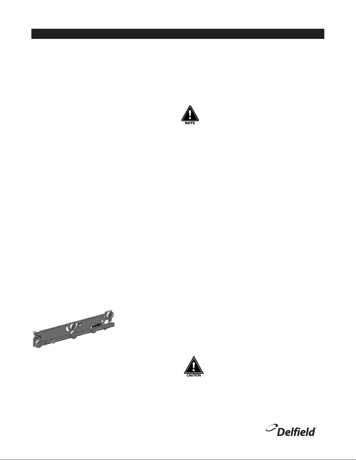
Tracks
The drawer box assembly must be removed. Pull the drawer tracks
out until they hit a stop. Locate blue safety clips towards the back
of each drawer track. Blue safety clips have a tab on the top. Push
the tab back until it clicks.
Lift up and pull the drawer
tracks all the way out of the
drawer cage. The drawer
tracks are dishwasher safe
or can be cleaned in a sink
with detergents and a soft
bristle brush. Drawers and
tracks should be cleaned on a weekly basis. Using a soft bristle brush,
wash the track making sure each roller is thoroughly cleaned. The
drawer cage should be cleaned with a soft bristle brush, removing
any food and debris gathered on the bottom ledge. Once it’s cleaned
thoroughly with a soft bristle brush, wipe remaining debris clean with
a soft towel.
Reassembly
Push the drawer tracks into the drawer cage. The blue safety clip
must remain pushed towards the back. Lift up and slide the drawer
track all the way into the drawer cage. The blue safety clip will lock
in place automatically. Once all tracks are replaced, insert the drawer
box. Rest the drawer box bottom track on the front track roller. Then
push the drawer back in place SLOWLY. When the drawer box is about
half way in you will hit a STOP. You must lift the front of the drawer up
approximately ½” (1.3cm) to continue inward. Clean tracks as often
as possible. The cleaner the tracks are the better they will operate.
Caster Maintenance
Wipe casters with a damp cloth monthly to prevent corrosion.
The power switch must be turned to OFF and the
unit disconnected from the power source whenever
performing service, maintenance functions or cleaning
the refrigerated area.
Refrigerators and Freezers
The interior and exterior can be cleaned using soap and warm water.
If this isn’t sufficient, try ammonia and water or a nonabrasive liquid
cleaner. When cleaning the exterior, always rub with the “grain” of
the stainless steel to avoid marring the finish. Do not use an abrasive
cleaner because it will scratch the stainless steel and can damage the
breaker strips and gaskets.
Stainless Steel Care and Cleaning
To prevent discoloration of rust on stainless steel several important
steps need to be taken. First, we need to understand the properties
of stainless steel. Stainless steel contains 70- 80% iron, which will
rust. It also contains 12-30% chromium, which forms an invisible
passive film over the steels surface, which acts as a shield against
corrosion. As long as the protective layer is intact, the metal is still
stainless. If the film is broken or contaminated, outside elements
can begin to breakdown the steel and begin to form discoloration of
rust. Proper cleaning of stainless steel requires soft cloths or plastic
scouring pads.
NEVER USE STEEL PADS, WIRE BRUSHES OR SCRAPERS!
Cleaning solutions need to be alkaline based or non-chloride cleaners.
Any cleaner containing chlorides will damage the protective film of
the stainless steel. Chlorides are also commonly found in hard water,
salts, and household and industrial cleaners. If cleaners containing
chlorides are used be sure to rinse repeatedly and dry thoroughly.
Routine cleaning of stainless steel can be done with soap and water.
Extreme stains or grease should be cleaned with a non-abrasive
cleaner and plastic scrub pad. Always rub with the grain of the
steel. There are stainless steel cleaners available which can restore
and preserve the finish of the steels protective layer. Early signs of
stainless steel breakdown are small pits and cracks. If this has begun,
clean thoroughly and start to apply stainless steel cleaners in attempt
to restore the passivity of the steel.
Never use an acid based cleaning solution! Many food
products have an acidic content, which can deteriorate
the finish. Be sure to clean the stainless steel surfaces
of ALL food products. Common items include, tomatoes,
peppers and other vegetables.
Cleaning the Condenser Coil
In order to maintain proper refrigeration performance, the
condenser fins must be cleaned of dust, dirt and grease regularly.
It is recommended that this be done at least every three months.
tab on top of
blue safety clip

18600 and CTP-NB Series Service and Installation Manual
11
For customer service, call (800) 733-8829, (800) 773-8821, Fax (989) 773-3210, www.delfield.com
Care & Cleaning, continued
If conditions are such that the condenser is totally blocked in three
months, the frequency of cleaning should be increased. Clean the
condenser with a vacuum cleaner or stiff brush. If extremely dirty, a
commercially available condenser cleaner may be required.
Failure to maintain a clean condenser coil can initially cause high
temperatures and excessive run times. Continuous operation with
a dirty or clogged condenser coil can result in compressor failure.
Neglecting the condenser coil cleaning procedures will void any
warranties associated with the compressor and cost to replace the
compressor.
Never use a high-pressure water wash for this
cleaning procedure as water can damage the electrical
components located near or at the condenser coil.
Doors/Hinges
Over time and with heavy use doors the hinges may become loose. If
this happens tighten the screws that mount the hinge brackets to the
frame of the unit. Loose or sagging doors can cause the hinges to pull
out of the frame, which may damage both the doors and the hinges. In
some cases this may require qualified service agents or maintenance
personnel to perform repairs.
Do not place hot pans on/against the blue ABS liner.
Do not throw items into the storage area. Failure to
follow these recommendations could result in damage
to the interior of the cabinet or to the blower coil.
Overloading the storage area, restricting the airflow,
and continuous opening and closing of the doors and
drawers will hamper the units ability to maintain
operational temperature.
Refrigerated rail units
Product in the rail should be removed to the refrigerated base at the
end of the day. This allows you to turn the rail off at night to save
energy and to defrost the rail. It also helps maintain product quality.
The standard wrapped refrigerated rail units are controlled by a low-
pressure control that is set to maintain the proper rail temperature.
An on/off switch is also provided for the rail and is required to be shut
off at night. With a LiquiTec rail a thermostat is provided to maintain
rail temperature as well as the rail on/off switch. The LiquiTec rail
is required to be shut off at night as well to allow for defrosting. To
ensure product quality in the rail it is recommended that product be
rotated every four hours.
If adding any item to the unit, be sure to keep in mind
the location of the refrigeration lines on wrapped rail
units. A refrigeration leak in a rail is extremely difficult
and costly to repair. In some cases it cannot be repaired
at all.
Preventing blower coil corrosion
To help prevent corrosion of the blower coil, store all acidic items,
such as pickles and tomatoes, in sealable containers. Immediately
wipe up all spills.
Units with pans should be operated with pans in place.
Operating the unit without all pans in place will lower
efficiency and may damage the unit.
Continuous opening and closing of the doors will hamper the unit’s
ability to maintain optimum refrigeration temperature. Top section is
not intended for overnight storage. Product should be removed from
pans. Pans can remain in unit while empty.

18600 and CTP-NB Series Service and Installation Manual
For customer service, call (800) 733-8829, (800) 773-8821, Fax (989) 773-3210, www.delfield.com
12
Wiring Diagram - 18600PTBM Series
Wiring Diagram - 18600PTL Series

18600 and CTP-NB Series Service and Installation Manual
13
For customer service, call (800) 733-8829, (800) 773-8821, Fax (989) 773-3210, www.delfield.com
Wiring Diagram - 18600BUCM & BSTM Series
Wiring Diagram - 18600PDL Series

18600 and CTP-NB Series Service and Installation Manual
For customer service, call (800) 733-8829, (800) 773-8821, Fax (989) 773-3210, www.delfield.com
14
POWER SWITCH
CONDENSING UNIT
TEMPERATURE CONTROLS THE CONDENSING UNIT
L1 N
G
Wiring Diagram - CTP-NB Series

18600 and CTP-NB Series Service and Installation Manual
15
For customer service, call (800) 733-8829, (800) 773-8821, Fax (989) 773-3210, www.delfield.com
18600PTBM Replacement Parts
All 18600PTBM Models
3234290 1" Shelf Support
9321132 1.5" Shelf Support Screw
3234160 Caster, 5, Plate ,Swivel
3234161 Caster, 5, Plate, Swivel, Break
3234392 Hinge, Pan Cover, Center
3234282 Hinge, Pan Cover, End, LH
3234266 Hinge, Pan Cover, End, RH
2190154 Switch, Rocker, 20A/125V,
186114PTBM 18699PTBM 18691PTBM 18672PTBM 18660PTBM 18648PTBM
*000-BN5-0030 Assembly, 1/4 HP Condensing Unit X
*000-BN5-0037 Assembly, 1/3 Condensing Unit X
*000-BN5-0035 Assembly, 1/2 HP Condenser, Med X X X
*000-BN5-0036 Assembly, 3/4 HP Condenser, Med X
*000-187-007Y Assembly, Dr, Ref, 19X26, LT, 430 X
*000-187-007X Assembly, Dr, Ref, 19X26, RT, 430 X
*000-187-0082 Assembly, Dr, Ref, 27X26, LT, 430 X X X
*000-187-0081 Assembly, Dr, Ref, 27X26, RT,430 X X X X
*000-187-0084 Assembly, Dr, Ref, 32X26, LT, 430 X
*000-187-0083 Assembly, Dr, Ref, 32X26, RT, 430 X
*000-402-004Q Assembly, Hinged Cover, 6 Pan, RT X
*000-402-004V Assembly, Hinged Cover, 8 Pan X
*000-402-004U Assembly, Hinged Cover, 8 Pan, RT X
*000-402-004X Assembly, Hinged Cover, 10 Pan, LT X X
*000-402-004Y Assembly, Hinged Cover, 10 Pan, RT X X
*000-402-0050 Assembly, Hinged Cover, 12 Pan X
*000-402-0051 Assembly, Hinged Cover, 12 Pan, LT X X
*000-402-0052 Assembly, Hinged Cover, 12 Pan, RT X
*000-282-006I Assembly, Control, Tstat & Pressure Control X
*000-282-006D Assembly, Tstat & Low Pressure Control X X X
*000-282-006C Assembly, Tstat & Low Pressure Control X X
*000-248-0030 Coil Assembly, R404A X X X X X
*000-248-0037 Coil Assembly, R404A, Fan Lt X
*359-478-003C Panel, Louver, 14.0, PTB X
*359-478-003E Panel, Louver, 15.0, PTB X
*359-478-003D Panel, Louver, 18.0, PTB X X X X
3977984 Shelf, Wire, 19X32DP X X
3977983 Shelf, Wire, 32X32 DP X
3978014 Shelf, Wire, Coated X X X X X
*Exploded assemblies and part prints are on the following pages.

18600 and CTP-NB Series Service and Installation Manual
For customer service, call (800) 733-8829, (800) 773-8821, Fax (989) 773-3210, www.delfield.com
16
All 18600BUCM Models
3234290 1" Shelf Support
9321132 1.5" Shelf Support Screw
3234160 Caster, 5, Plate, Swivel
3234161 Caster, 5, Plate, Swivel, Brake
*000-298-003P Control Assembly
186114BUCM 18699BUCM 18691BUCM 18672BUCM 18660BUCM 18648BUCM
*000-BN5-0031 Assembly, 1/5 Condensing Unit X X
*000-BN5-0030 Assembly, 1/4 HP Condensing Unit X X X
*000-BN5-0037 Assembly, 1/3 Condensing Unit X
*000-187-007Y Assembly, Dr, Ref, 19X26, LT, 430 X
*000-187-007X Assembly, Dr, Ref, 19X26, RT, 430 X
*000-187-0082 Assembly, Dr, Ref, 27X26, LT, 430 X X X X
*000-187-0081 Assembly, Dr, Ref, 27X26, RT, 430 X X X X
*000-187-0084 Assembly, Dr, Ref, 32X26, LT, 430 X
*000-187-0083 Assembly, Dr, Ref, 32X26, RT, 430 X
*000-248-0030 Coil Assembly, R404A X X X X X
*000-248-0037 Coil Assembly, R404A, Fan Lt X
*359-478-0040 Panel, Louver, 14, Hanging X
*359-478-0042 Panel, Louver, 15, Hanging X
*359-478-0041 Panel, Louver, 18, Hanging X X X X
3977984 Shelf, Wire, 19X32DP X X
3977983 Shelf, Wire, 32X32DP X
3978014 Shelf, Wire, Coated X X X X X
*Exploded assemblies and part prints are on the following pages.
18600BUCM Replacement Parts

18600 and CTP-NB Series Service and Installation Manual
17
For customer service, call (800) 733-8829, (800) 773-8821, Fax (989) 773-3210, www.delfield.com
All 18600BSTM Models
3234290 1" Shelf Support
9321132 1.5" Shelf Support Screw
3234160 Caster, 5, Plate, Swivel
3234161 Caster, 5, Plate, Swivel, Brake
*000-298-003P Control Assembly
186114BSTM 18699BSTM 18691BSTM 18672BSTM 18660BSTM 18648BSTM
*000-BN5-0031 Assembly, 1/5 Condensing Unit X X
*000-BN5-0030 Assembly, 1/4 HP Condensing Unit X X X
*000-BN5-0037 Assembly, 1/3 Condensing Unit X
*000-187-007Y Assembly, Dr, Ref, 19X26, LT, 430 X
*000-187-007X Assembly, Dr, Ref, 19X26, RT, 430 X
*000-187-0082 Assembly, Dr, Ref, 27X26, LT, 430 X X X X
*000-187-0081 Assembly, Dr, Ref, 27X26, RT, 430 X X X X
*000-187-0084 Assembly, Dr, Ref, 32X26, LT, 430 X
*000-187-0083 Assembly, Dr, Ref, 32X26, RT, 430 X
*000-248-0030 Coil Assembly, R404A X X X X X
*000-248-0037 Coil Assembly, R404A, Fan Lt X
*359-478-0040 Panel, Louver, 14, Hanging X
*359-478-0042 Panel, Louver, 15, Hanging X
*359-478-0041 Panel, Louver, 18, Hanging X X X X
3977984 Shelf, Wire, 19X32DP X X
3977983 Shelf, Wire, 32X32DP X
3978014 Shelf, Wire, Coated X X X X X
All 18600PTL Models
3234290 1" Shelf Support 3516053 Coil, Solenoid, 120V
9321132 1.5" Shelf Support Screw 3234392 Hinge, Pan Cover, Center
*000-187-0082 Assembly, Dr, Ref, 27X26, LT, 430 3234282 Hinge, Pan Cover, End, LH
*000-402-0055 Assembly, Hinged Cover, 12 Pan, PTL 3234266 Hinge, Pan Cover, End, RH
263-ASB-0030 Bracket, Cutting Board, Center 3978014 Shelf, Wire, Coated
263-110-0034 Bracket, Cutting Board, LH 2190154 Switch, Rocker, 20A/125V
263-110-0036 Bracket, Cutting Board, RF 3516225 Valve, Expansion, Frz, 1/4Ton
3234160 Caster, 5, Plate, Swivel 3516102 Valve, Solenoid, 1/4ODF
3234161 Caster, 5, Plate, Swivel, Brake
18699PTL 18672PTL 18648PTL
*000-BN5-0030 Assembly, 1/4 HP Condensing Unit X
*000-BN5-0035 Assembly, 1/2HP Condenser, MED X X
*000-282-006L Assembly, Control, 15A X
*000-282-006M Assembly, Control, 20A X X
*000-187-0081 Assembly, Dr, Ref, 27X26, RT, 430 X X
*000-402-0054 Assembly, Hinged Cover, 6 Pan, PTL X
*000-248-0030 Coil Assembly, R404A X X
*000-248-0037 Coil Assembly, R404A, Fan Lt X
18600BSTM & 18600PTL Replacement Parts

18600 and CTP-NB Series Service and Installation Manual
For customer service, call (800) 733-8829, (800) 773-8821, Fax (989) 773-3210, www.delfield.com
18
All CTP8000-NB Models
243-ALS-0032 Divider, Bar, Cold
3234392 Hinge, Pan Cover, Center
3234282 Hinge, Pan Cover, End, LH
3234266 Hinge, Pan Cover, End, RH
9321374 Pin, Hinge, Salad Pan
CTP8175-NB CTP8160-NB CTP8146-NB
*000-254-Z000B Condenser Assembly, 1/5HP, CTP-8100 X
*000-AUX-0038 Condensing Unit Assembly, 1/5HP, CTP X X
*223-016-Z000P Cover, Hinged, CTP X
*265-016-003U Cover, Pan, Rail, 8 Pan X
*265-016-003W Cover, Pan, Rail, 12 Pan X
243-ALS-0030 Divider, Bar, Cold X
243-ALS-0036 Divider, Bar, Cold X X
*356-411-Z0009 Louver, Front, CTP-8100 X
*026-411-Z000A Louver, Rear, CTP-8100 X
*356-411-0004 Panel, Louver, Front CTP-8100 X X
All 18600PDL Models
*000-187-0082 Assembly, Door, Ref, 27X26, LT, 430 3234266 Hinge, Pan Cover, End, RH
*000-402-0054 Assembly, Hinged Cover, 6 Pan, PTL 9321374 Pin, Hinge, Salad Pan
263-110-0034 Bracket, Cutting Board 3978014 Shelf, Wire, Coated
263-110-0036 Bracket, Cutting Board 3234290 Support, Shelf, Plastic
3234186 Caster, 3DIA, Swivel, Plate 2190154 Switch, Rocker, 20A/125V
3234392 Hinge, Pan Cover 3516135 Thermometer, Hanging, 4
3234282 Hinge, Pan Cover, End, LH
Part Number Description 18672PDL 18648PDL
*000-BN5-003Y Assembly, 1/2-1/5 Cond Unit Stacked X
*000-BN5-0040 Assembly, 1/3-1/5 Cond Unit Stacked X
*000-282-006V Assembly, Control, L/T, 48” X
*000-282-006K Assembly, Control, L/T, 72” X
*000-187-0081 Assembly, Door, Ref, 27X26, RT, 430 X
*000-248-0030 Coil Assembly, R404A X
*000-248-0037 Coil Assembly, R404A, Fan Lt X
*359-478-003E Panel, Louver, 15.0, PTB X
*359-478-003D Panel, Louver, 18.0, PTB X
*Exploded assemblies and part prints are on the following pages.
CTP8000-NB & 18600PDL Replacement Parts

18600 and CTP-NB Series Service and Installation Manual
19
For customer service, call (800) 733-8829, (800) 773-8821, Fax (989) 773-3210, www.delfield.com
Key Part Number Description
- 000-282-006I Thermostat & Dual Pressure Control Assembly
12193942 Dual pressure control
22190154 Rocker switch, 20A/125V
32194824 Control, Danfoss, GDM, 115V
1
2
3
Key Part Number Description
-000-282-006C &
000-282-006D
Thermostat & Low Pressure Control Assembly
12193927 Low pressure control
22190154 Rocker switch, 20A/125V
32194824 Control, Danfoss, GDM, 115V
1
2
3
Replacement Parts - Control Assemblies
Key Part Number Description
- 000-298-003P Control Assembly
12194810 Control, Danfoss, GDM, 115V
22190154 Rocker switch, 20A/125V
12
Key Part Number Description
- 000-282-006L &
000-282-006M
Control Assembly, LiquiTec, 2SW
12193927 Low pressure control
2000-282-0051 Tstat Assembly, Danfoss, MK7
32190154 Rocker switch, 20A/125V
42194824 Control, Danfoss, GDM, 115V
1234
123
12
Key Part Number Description
- 000-282-006K 72” LiquiTec Dual Rail Control Assembly
1000-282-0051 Tstat Assembly, Danfoss, MK7
22190154 Rocker switch, 20A/125V
32194824 Control, Danfoss, GDM, 115V
Key Part Number Description
- 000-282-006V 48” LiquiTec Dual Rail Control Assembly
1000-282-0053 Tstat Assembly, Danfoss, MK7
22190154 Rocker switch, 20A/125V
32194824 Control, Danfoss, GDM, 115V

18600 and CTP-NB Series Service and Installation Manual
For customer service, call (800) 733-8829, (800) 773-8821, Fax (989) 773-3210, www.delfield.com
20
1
2
4
5
6
8
3
7
1
2
4
5
6
7
8
3
Replacement Parts - Condensing Unit Assemblies
Key Part Number Description
-000-BN5-0030 Assembly, 1/4 HP Condensing Unit
13516457 Fan Blade
22160020 Fan Guard
32162717 Fan Motor
43526999 Compressor, Danfoss, NF5.5CLX
52194787 Start Capacitor
63516322 Filter Dryer
7 075-231-0030 Condensate Pan
83516454 Condenser Coil
- 000-BN5-0031 Assembly, 1/5 Condensing Unit
13516457 Fan Blade
22160020 Fan Guard
32162717 Fan Motor
43526997 Compressor, Danfoss, TF4CLS
52194787 Start Capacitor
63516322 Filter Dryer
7 075-231-0030 Condensate Pan
83516454 Condenser Coil
2
1
3
5
7
8
4
9
6
-000-BN5-0035 Assembly, 1/2HP Condenser, Med
13516554 Condenser fan blade
22160019 Condenser fan guard
32162716 Condenser fan motor, 115V
43516462 Capacitor, start-run assy
53527026 Compressor, Danfoss, SC12MLX
63516331 Hi pressure switch
73516322 Filter Drier
8 075-231-0031 Pan, Condensate
93516455 Condenser coil
Part Number Description
000-AUX-0038 Condensing Unit Assembly, 1/5HP, CTP
3526694 Compressor
3516082 Condenser Coil
3516172 Fan Blade
2162691 Fan Motor
031-264-0000 Fan Motor Bracket
3516191 Filter Drier
3516047 Temp Control
This manual suits for next models
31
Table of contents
Other Manitowoc Commercial Food Equipment manuals

Manitowoc
Manitowoc Garland Induction Designer Series User manual

Manitowoc
Manitowoc U65 User manual

Manitowoc
Manitowoc Cleveland KET-3-T User manual

Manitowoc
Manitowoc LuminIce User manual

Manitowoc
Manitowoc K00497 User manual

Manitowoc
Manitowoc Frymaster FilterQuick FQE30 User manual

Manitowoc
Manitowoc Delfield N8100B User manual