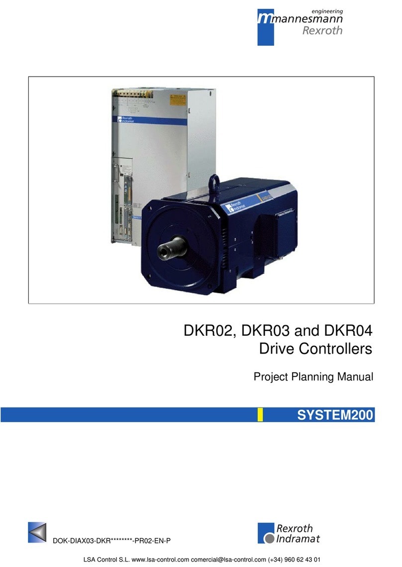
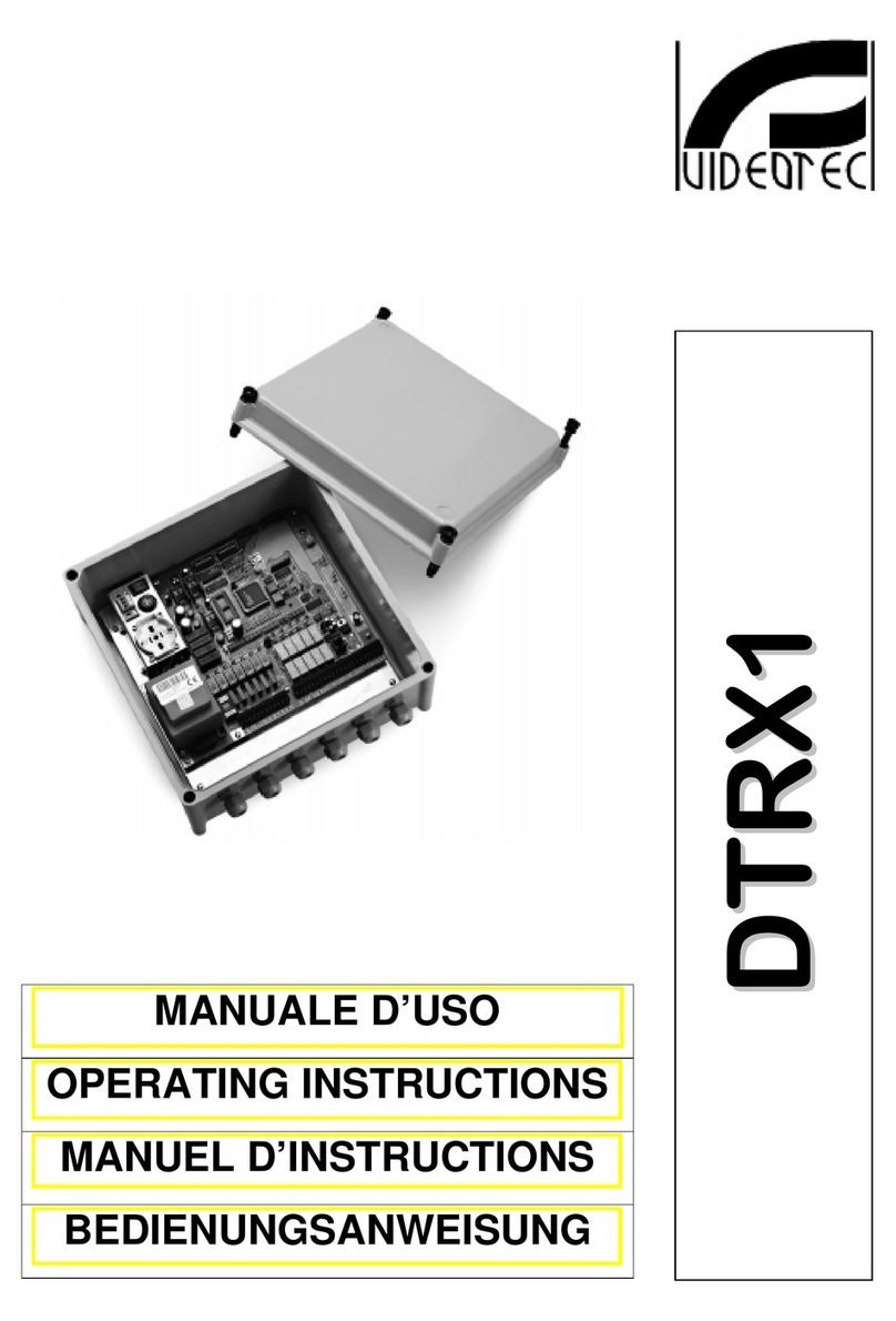
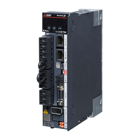
Mannesmann Rexroth Indramat ECODRIVE DKC01.1 Technical manual

ECODRIVE
DKC01.1/DKC11.1Drive Controllers
DOK-ECODRV-DKC01/11.1*-PRJ3-EN-P
Project Planning Manual
mannesmann
Rexroth
engineering
Indramat
270950

About this documentation ECODRIVE DKC01.1/DKC11.1 Drive Controllers
DOK-ECODRV-DKC01/11.1*-PRJ3-EN-P
ECODRIVE DKC01.1/DKC11.1 Drive Controllers
Project Planning
DOK-ECODRV-DKC01/11.1*-PRJ3-EN-P
• 209-0069-4390-03
Document identification of
previous editions Date Remark
209-0069-4390-00 EN/05.96
209-0069-4390-01 EN/06.96
DOK-ECODRV-DKC01/11.1*-PRJ1-EN-P
DOK-ECODRV-DKC01/11.1*-PRJ1-EN-P
DOK-ECODRV-DKC01/11.1*-PRJ3-EN-P
May 96
June 96
July 96
May 97
Feb. 98
First edition
Revision
2nd edition
2nd Revision
new edition
INDRAMAT GmbH, 1996
The reproduction and transmission of this document, the use and com-
munication of its content to third parties without the expressed consent of
INDRAMAT GmbH are forbidden. Violators are liable for the payment of
damages. All rights are reserved in the event a patent is granted or a util-
ity model is registered (DIN 34-1).
INDRAMAT GmbH •Bgm.-Dr.-Nebel-Str. 2 •D-97816 Lohr a. Main
Telephone +49 (09352) 40-0 •Telex 689421 •Fax +49 (09352) 40-4885
Dept. ENA (VS, HE)
The contents of this documentation and the availability of the product are
subject to change.
Title
Type of document
Document code
Internal file reference
Editing sequence
Copyright
Publisher
Validity

ECODRIVE DKC01.1/DKC11.1 Drive Controllers About this documentation
DOK-ECODRV-DKC01/11.1*-PRJ3-EN-P
It supplies information on:
• planning the mechanical control cabinet
• planning the electrical system in the control cabinet
• logistic handling of the equipment
• preparing the resources for start-up
"ECODRIVE DKC Servo Drives with MKD"
- Selection Lists -
DOK-ECODRV-DKC+MKD****-AUS1-EN-P
for selecting the motor controller combination.
"MKD Digital AC Motors"
- Project Planning Manual -
DOK-MOTOR*-MKD********-PRJ2-EN-P
for a detailed description of the servomotors and for the selection of the
required cable.
"ECODRIVE DKC01.1/DKC11.1 Drive Controllers"
- Description of Functions -
DOK-ECODRV-DKC01/11.1-FKB1-EN-P
for testing and selecting the functions.
"EMC in Drive and Control Systems"
- Project Planning -
209-0049-4305-02 EN/04.96
for the EMC-compliant planning and installation of the drive system (EMC
= Electromagnetic Compatibility).
What is this
documentation for?
Supplementary documentation

About this documentation ECODRIVE DKC01.1/DKC11.1 Drive Controllers
DOK-ECODRV-DKC01/11.1*-PRJ3-EN-P
Notes

ECODRIVE DKC01.1/DKC11.1 Drive Controllers Table of contents I
DOK-ECODRV-DKC01/11.1*-PRJ3-EN-P
Table of contents
1 Introduction to the system 1-1
1.1 Application features..............................................................................................................................1-1
1.2 Overview of the functions.....................................................................................................................1-1
2 Safety instructions for electrical drives 2-1
2.1 General ................................................................................................................................................2-1
2.2 Protection against contact with electrical parts....................................................................................2-2
2.3 Protection against shocks caused by safety extra-low voltage (SELV).........................................2-3
2.4 Protection against dangerous movements...........................................................................................2-4
2.5 Protection against magnetic and electromagnetic fields during operation and assembly ...................2-6
2.6 Protection during handling and assembly............................................................................................2-7
2.7 Safe battery usage...............................................................................................................................2-7
3 Selecting the components 3-1
3.1 Overview of the required components.................................................................................................3-1
3.2 Selection procedure.............................................................................................................................3-2
3.3 Compiling the required data.................................................................................................................3-3
4 ECODRIVE DKC drive controllers 4-1
4.1 Hardware..............................................................................................................................................4-1
View of unit....................................................................................................................................4-1
Dimensional sheets and installation dimensions...........................................................................4-2
Technical data...............................................................................................................................4-4
Type code and rating plate............................................................................................................4-7
4.2 Firmware..............................................................................................................................................4-8
4.3 An overview of the electrical connections............................................................................................4-9
Front view with supply terminals...................................................................................................4-9
Overall connection diagrams.......................................................................................................4-10
4.4 Electrical connection to the supply terminal strips.............................................................................4-14
Serial interface X1.......................................................................................................................4-14
X2 positioning or stepper interface..............................................................................................4-18
X3 analog inputs and outputs......................................................................................................4-25
X4 terminals for the control circuit...............................................................................................4-29
X5, X6, X7 motor connections ....................................................................................................4-30
X9 DC bus connection ................................................................................................................4-30

II Table of contents ECODRIVE DKC01.1/DKC11.1 Drive Controllers
DOK-ECODRV-DKC01/11.1*-PRJ3-EN-P
5 BZM auxiliary bleeder module 5-1
5.1 Dimensioning the components relevant for regeneration ....................................................................5-1
5.2 Dimensional data and installation dimensions.....................................................................................5-5
5.3 Technical data......................................................................................................................................5-6
5.4 Front view.............................................................................................................................................5-6
5.5 Electrical connections..........................................................................................................................5-7
5.6 Type code and rating plate...................................................................................................................5-7
6 CZM Auxiliary Capacitance Module 6-1
6.1 Dimensioning .......................................................................................................................................6-1
6.2 Dimensional data and installation dimensions.....................................................................................6-3
6.3 Front view.............................................................................................................................................6-4
6.4 Electrical connection............................................................................................................................6-4
6.5 Type code and rating plate...................................................................................................................6-5
7 DC24V NTM power supplies 7-1
7.1 Application recommendations..............................................................................................................7-1
7.2 Technical data......................................................................................................................................7-1
7.3 Dimensional data and installation dimensions.....................................................................................7-2
7.4 Front views...........................................................................................................................................7-2
7.5 Electrical connection............................................................................................................................7-3
7.6 Type code ............................................................................................................................................7-4
8 NFD / NFE line filter 8-1
8.1 Selection ..............................................................................................................................................8-1
8.2 Dimensional data and installation dimensions.....................................................................................8-2
8.3 Electrical connection............................................................................................................................8-3
8.4 Line filters for DC24V NTM power supplies.........................................................................................8-5
8.5 Type code ............................................................................................................................................8-5
9 DST / DLT transformers 9-1
9.1 Selection ..............................................................................................................................................9-1
9.2 Autotransformers for DKC**.*-040-7-FW.............................................................................................9-1
9.3 Autotransformers for DKC**.*-030-3-FW.............................................................................................9-4
9.4 Electrical connection of the DKC via transformer ................................................................................9-6
9.5 Type code ............................................................................................................................................9-7
10 Planning the control cabinet 10-1
10.1 Notes on installing the control cabinet.............................................................................................10-1
Power dissipation........................................................................................................................10-1
10.2 Using heat-exchange units in the control cabinets ..........................................................................10-2

ECODRIVE DKC01.1/DKC11.1 Drive Controllers Table of contents III
DOK-ECODRV-DKC01/11.1*-PRJ3-EN-P
11 Power connection 11-1
11.1 Direct power connection...................................................................................................................11-1
11.2 Line contactor/fuse protector ...........................................................................................................11-2
Calculating the phase current at the power connection..............................................................11-2
Selecting fuse protector Q1 and line contactor K1......................................................................11-3
11.3 Control circuit to the power connection............................................................................................11-4
11.4 Protection against indirect contact...................................................................................................11-5
12 Preparing for Startup 12-1
Required equipment....................................................................................................................12-1
13 Condition of the drive components on delivery 13-1
Packaging ...................................................................................................................................13-1
Accompanying documents..........................................................................................................13-1
Identification of the components .................................................................................................13-1
14 Index 14-1

IV Table of contents ECODRIVE DKC01.1/DKC11.1 Drive Controllers
DOK-ECODRV-DKC01/11.1*-PRJ3-EN-P
Notes

ECODRIVE DKC01.1/DKC11.1 Drive Controllers Introduction to the system 1-1
DOK-ECODRV-DKC01/11.1*-PRJ3-EN-P
1 Introduction to the system
1.1 Application features
The drive system with the ECODRIVE drive controllers is the most cost-
effective solution offering the highest functionality for almost any field of
application in which translatory or rotary motions are to be automated.
Outstanding performance data, an extensive range of functions as well as
an excellent price-to-performance ratio represent the salient features of
this drive system.
Product features in terms of the technical applications are:
• universal implementation
• lower total costs
• digital drive concept
• highly dynamic operation
• cost-effective direct connection to the power connection
• software travel limit switch
• absolute or incremental position detection
• absolute or incremental position output
• integrated holding brake control
• increased operating safety
• adjustable error response
• automatic parameter matching
• easy startup operation
1.2 Overview of the functions
The functions of the digital, intelligent drive system are differentiated pri-
marily according to the interface of the higher-level control. The fields of
application for the ECODRIVE drive controllers vary accordingly.
The drive controller DKC01.1 is used as a:
• servodrive with integrated position control
• servodrive with analog speed interface and integrated actual position
detection
• servodrive with stepper interface.
• servodrive with electronic gearbox function
The drive controller DKC11.1 represents a particularly cost-effective solu-
tion. It is used as a:
• servodrive with analog speed interface and integrated actual position
detection

1-2 Introduction to the system ECODRIVE DKC01.1/DKC11.1 Drive Controllers
DOK-ECODRV-DKC01/11.1*-PRJ3-EN-P
Servodrive with integrated position control
SPS-Control DKC01.1Drive controller
with POSITIONING-interface AC-servo motor
MKD
I/O _ card
Selection
of the
positioning
records
Control inputs
Status outputs
Actual
position
value
MS-DOS - PC
®
Parameters
Diagnosis
Operating data
RS 485
Stored
positioning
records
Fine interpolation
Position control
Speed control
Field-orinted
stator current
control
2° position 1
21position 2
22.
.
24position 32
Drive processor
M
3~
~
FS0200.fh5
High-resolution
positioning interface
~
RS 232
Fig. 1-1: Servodrive with integrated position control
• Up to 32 positioning blocks can be stored in the drive controller and
selected over parallel inputs. The positioning block is executed
autonomously.
• Mechanical translatory elements such as gear ratios or feed constants
are adapted in the drive.
• All position, speed, and acceleration data can be weighted independ-
ently of the axis kinematics.
• A drive-internal referencing procedure is available for creating a refer-
ence dimension.
• The axis can be moved with the jog function during setup operation.
• The positioning speed can be influenced via the feedrate override.
• Travel limit switch inputs and axis limit values which can be parame-
terized are available for limiting the travel range.
• The drive status can be detected via status outputs.

ECODRIVE DKC01.1/DKC11.1 Drive Controllers Introduction to the system 1-3
DOK-ECODRV-DKC01/11.1*-PRJ3-EN-P
Servodrive with analog speed interface and integrated actual
position detection
M
Kv
+W
-X
A
DA
D
RS 485
FS0201.fh5
RS 232
®
3
~
~
~
DKC01.1 or DKC11.1 drive
controller with ANALOG interface MKD
AC servo motor
Control unit
with position control
Positioning
interface
Speed
Actual
position
value
analog
Drive processor
Speed control
Field-oriented
stator current
control
Linear scale
High-resolution
positioning interface
Position
command
value
Diagnosis
Operating data
Parameters
MS-DOS - PC
Parameters
Diagnosis
Operating data
command
value
±10V
Fig. 1-2: Servodrive with analog speed interface and integrated actual position
detection
• The analog speed command value can be set to any value.
• The actual position value is output either incrementally or absolutely.
• Using a switching input, the drive can be shut down independent of the
command value and stopped free of drift during active control.

1-4 Introduction to the system ECODRIVE DKC01.1/DKC11.1 Drive Controllers
DOK-ECODRV-DKC01/11.1*-PRJ3-EN-P
Servodrive with stepper interface
M
RS 485
FS0202.fh5
MS-DOS - PC
®
RS 232
3
~
~
~
DKC01.1 drive controller
with STEPPER interface MKD
AC servo motor
Control unit
with step pulse generation
Drive processor
Fine interpolation
Position control
Speed control
Field-oriented
stator current
control
High-resolution
position interface
Interpolation
Actual
position
value
forwards
backwards
Stepper
interface
Step pulse
generation
Parameters
Operating data
Diagnosis
Fig. 1-3: Servodrive with stepper interface
• The number of steps per rotor rotation can be set to any value be-
tween 16 and 65536.
• The maximum step frequency is independent of the load. It is techni-
cally impossible to "skip" steps due to the position controlled operation.
• The stepper interface can be set to three standard signal definitions for
exchanging signals between the control and the drive controller.
- quadrature signals
- forwards/backwards signals
- step and direction signal
• A drive-internal referencing procedure is available for creating a refer-
ence dimension.
• The axis can be moved with the jog function during setup operation.
• The referencing and jog speed can be influenced via the feedrate
override.
• Travel limit switch inputs and axis limit values which can be parame-
terized are available for limiting the travel range.

ECODRIVE DKC01.1/DKC11.1 Drive Controllers Introduction to the system 1-5
DOK-ECODRV-DKC01/11.1*-PRJ3-EN-P
Servodrive with electronic gearbox function
M
Servodrive DKC01.1
with electronic gearbox function AC-Servomotor
MKD
Drive processor
electronic gearbox
Position control
Speed control
Field-oriented
stator current
control
High-resolution
position interface
RS 485
Step motor
interface
Lead axis
transmitter
FS0203.fh5
MS-DOS - PC
®
Parameters
Diagnosis
Operating data
RS 232
Lead axis
position 3~
~
~
Fig. 1-4: Servodrive with electronic gearbox function
• Operating modes
Speed synchronization
Angle synchronization
• The lead axis position is given in degrees (360 degrees represent one
lead axis encoder revolution)
• The lead axis encoder must be connected to the DKC stepper inter-
face.
The maximum allowable signal frequency fmax on the stepper interface
limits the number of lines Zlwhich can be emulated.

1-6 Introduction to the system ECODRIVE DKC01.1/DKC11.1 Drive Controllers
DOK-ECODRV-DKC01/11.1*-PRJ3-EN-P
Notes

ECODRIVE DKC01.1/DKC11.1 Drive Controllers Safety instructions for electrical drives 2-1
DOK-ECODRV-DKC01/11.1*-PRJ3-EN-P
2 Safety instructions for electrical drives
Please read the following instructions carefully before initial startup.
These safety instructions must be observed at all times.
If the product is transferred to a third-party, the safety instructions must be
included.
WARNING
Improper use of this equipment and non-compliance
with the safety instructions provided can result in
damage, personal injury or, in extreme cases, death.
2.1 General
INDRAMAT GmbH is not liable for any damages resulting from failure
to observe the safety instructions in this document.
• Documentation in the relevant national language should be obtained
before initial startup if the language in this documentation is not per-
fectly understood.
• Proper transport, correct storage, assembly, and installation as well as
care in operation and maintenance are prerequisites for optimum and
safe operation of this equipment.
• Qualified personnel:
Only qualified personnel should be permitted to operate this equipment
or work in its immediate vicinity. Personnel is considered qualified if it
has sufficient knowledge of the assembly, installation, and operation of
the product as well as all warnings and precautionary measures in this
documentation.
Furthermore, personnel should be trained, instructed or authorized to
switch electrical circuits on and off and to ground and mark them in
accordance with the requirements of safety engineering. Personnel
should possess adequate safety equipment and be trained in first aid.
• Use only replacement parts approved by the manufacturer.
• All safety regulations and requirements for the specific application
must be followed.
• The equipment is designed to be installed in machines for commercial
use.
• Startup is only permitted once it is sure that the machine in which the
products are installed complies with the requirements of the national
safety regulations and safety specifications of the application.
European countries: EC Directive 89/392/EEC (Machine Guideline)
• Operation is only permitted if the national EMC regulations for the spe-
cific application have been met. European countries: EC Directive
89/336/EEC (EMC Guideline)
The instructions for installation in accordance with EMC requirements
can be found in the document "EMC Drive and Control Systems."
The responsibility for adherence to the limiting values required by na-
tional regulations lies with the manufacturer of the equipment or ma-
chine.

2-2 Safety instructions for electrical drives ECODRIVE DKC01.1/DKC11.1 Drive Controllers
DOK-ECODRV-DKC01/11.1*-PRJ3-EN-P
• Technical specifications as well as the connection and installation re-
quirements can be found in the product documentation and must be
observed under all circumstances.
2.2 Protection against contact with electrical parts
Note: Only relevant for devices and drive components with voltages ex-
ceeding 50 volts.
Coming into contact with components carrying voltages greater than 50
volts can be dangerous. Certain parts are under dangerous voltage when
operating electrical devices.
DANGER
High Voltage!
Danger to life or risk of bodily injury!
⇒ Follow general construction and safety regulations
when working on electrical installations.
⇒ Before switching on power, be sure that the ground
wire is permanently connected to all electrical units
according to the connection diagram.
⇒ At no time may electrical equipment be operated if the
ground wire is not permanently connected to the
proper terminals, even for brief measurements or
tests.
⇒ Disconnect the equipment from the power supply line
or the voltage source before beginning work. Secure
equipment from reclosure.
⇒ Wait 5 minutes after switching off power to allow ca-
pacitors to discharge before using the equipment.
Measure the voltage of the capacitors before begin-
ning work in order to eliminate dangers arising from
touching components.
⇒ Never touch the electrical connection points of a com-
ponent while the power is turned on.
⇒ Cover live parts properly before switching the equip-
ment on so they cannot be touched. Covers provided
with the equipment must be installed before operating
the equipment to prevent contact with live parts. The
equipment may only be operated with the covers de-
signed for shock-hazard protection.
⇒ A GFCI protective device (ground fault circuit inter-
rupter) cannot be used for AC drives! Protection
against indirect contact must be ensured by other
means, for example, by using an overcurrent protec-
tion device in accordance with relevant standards.
European countries: in accordance with EN
50178/1994, section 5.3.2.3
⇒ For installation equipment protection against indirect
contact must be ensured using an external housing,
such as a control cabinet. European countries: in ac-
cordance with EN 50178/1994, section 5.3.2.3

ECODRIVE DKC01.1/DKC11.1 Drive Controllers Safety instructions for electrical drives 2-3
DOK-ECODRV-DKC01/11.1*-PRJ3-EN-P
WARNING
High discharge current!
Danger to life or risk of bodily injury!
⇒ All units and the motors must first be connected to a
grounding point with the ground wire or must be
grounded themselves before switching on power.
⇒ The discharge current is greater than 3.5 mA. A per-
manent connection to the power supply line is there-
fore required for all units. European countries (EN
50178/1994, section 5.3.2.3)
⇒ Before startup operation always connect the protec-
tive conductor or the ground conductor. Otherwise the
housing may harbor high voltages.
2.3 Protection against shocks caused by safety extra-low
voltage (SELV)
All connectors and terminals on INDRAMAT products with voltages from
5 to 50 volts are safety extra-low voltages offering a shockproof design to
meet the following standards:
• international: IEC 364-4-411.1.5
• European countries in the EC: EN 50178/1994, section 5.2.8.1
WARNING
High electrical voltages due to incorrect connec-
tions!
Danger to life or risk of bodily injury!
⇒ Only equipment and lines carrying protective extra low
voltage (PELV) may be connected to connectors and
terminals with voltages ranging from 0 to 50 volts.
⇒ Connect only voltages and circuits safely isolated from
dangerous voltages. Isolation can be achieved, for
example, by using safe isolation transformers, opto-
couplers or power supply independent battery opera-
tion.

2-4 Safety instructions for electrical drives ECODRIVE DKC01.1/DKC11.1 Drive Controllers
DOK-ECODRV-DKC01/11.1*-PRJ3-EN-P
2.4 Protection against dangerous movements
Dangerous movements can be caused if the connected motors are not
controlled correctly.
There are various causes of dangerous movements:
• faulty wiring or cable connections
• operating the components improperly
• defective measured value transmitters and primary detectors
• defective components
• errors in the software
These errors can occur just after the equipment has been switched on or
after an indefinite period of time.
The monitors in the drive components virtually exclude failure in the con-
nected drives. However, personnel safety requires that additional meas-
ures be taken to ensure correct operation. Faulty drive motions which are
influenced by the type of control and the operating status cannot be en-
tirely excluded until the installed monitors take effect.

ECODRIVE DKC01.1/DKC11.1 Drive Controllers Safety instructions for electrical drives 2-5
DOK-ECODRV-DKC01/11.1*-PRJ3-EN-P
DANGER
Dangerous movements!
Danger may result in equipment damage, personal injury
or death!
⇒ Personal safety must be ensured by higher-level,
monitoring at the installation or precautionary meas-
ures for the reasons listed above. These are provided
by the plant manufacturer according to the specific
conditions of the plant based on a danger and mal-
function analysis. The safety regulations in effect for
the plant are included herein.
Avoiding accidents:
⇒ Stay away from the machine’s movement area. Pos-
sible measures to be taken to prevent access by un-
authorized persons:
- protective fence
- protective railing
- protective covering
- light barrier
⇒ Fences and coverings should be strong enough to
withstand the maximum possible momentum.
⇒ Mount the emergency stop switch (E-stop) at an easily
accessible place in the immediate vicinity. Verify that
the E-stop switch works before starting operation.
⇒ Isolate the drive power connection by means of an E-
stop circuit or use a starting lock-out to prevent unin-
tentional startup.
⇒ Make sure that the drives have been shut down be-
fore accessing or entering the danger zone.
⇒ Disable electrical power to the equipment using a
master switch and secure against reclosure during:
- maintenance and repair work
- equipment cleaning
- long downtime periods
⇒ Avoid operating high-frequency, remote control, and
radio equipment near electrical equipment and their
supply leads. If the use of such equipment cannot be
avoided, verify that the system and plant are in perfect
working order in all working situations before initial
operation. If necessary, the plant must undergo spe-
cial EMC testing.

2-6 Safety instructions for electrical drives ECODRIVE DKC01.1/DKC11.1 Drive Controllers
DOK-ECODRV-DKC01/11.1*-PRJ3-EN-P
2.5 Protection against magnetic and electromagnetic fields
during operation and assembly
Magnetic and electromagnetic fields near current-carrying conductors and
permanent magnets pose a serious health hazard for persons with pace-
makers, metal implants and hearing aids.
WARNING
Health hazard for persons with pacemakers, metal
implants and hearing aids in the immediate vicinity
of electrical equipment.
⇒ Persons with pacemakers and metal implants must
not be permitted access to the following areas:
− Areas in which electrical equipment and parts are
mounted, operated or put into operation.
− Areas in which motor parts with permanent mag-
nets are stored, repaired or mounted.
⇒ If it becomes necessary for a person with a pace-
maker to enter such an area, this must be approved
by a physician beforehand.
Implanted pacemakers or those to be implanted have
a varying degrees of resistance to interference, mak-
ing it impossible to establish any general guidelines.
⇒ Persons with metal implants or metal splitters as well
as hearing aids should consult a physician before en-
tering such areas since they represent a health haz-
ard.
This manual suits for next models
1
Table of contents
Other Mannesmann Rexroth Controllers manuals
