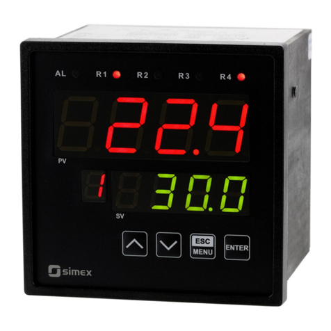
Simex MultiCon CMC-99/141 User manual

Assisting the automation
industry since 1986
User manual
CONTROLLER/ ATA RECOR ER
MultiCon CMC-99/141
•Firmware: v.5.03.0 or higher
Read the user's manual carefully before starting to use the unit or software.
The producer reserves the right to change any part of this document at any time
without prior notice.
2018.10.08 ultiCon C C-99/141_INSSXEN_v.1.21.006

User Manual For - CONTROLLER/DATA RECORDER MultiCon CMC-99/141
CONTENTS
1. BASIC REQUIREMENTS AND USER SAFETY.......................................................................................5
1.1. TOUCH-SCREEN USE.....................................................................................................................6
2. GENERAL CHARACTERISTICS...............................................................................................................6
3. TECHNICAL DATA....................................................................................................................................9
4. DEVICE INSTALLATION.........................................................................................................................10
4.1. UNPACKING...................................................................................................................................11
4.2. ASSEMBLY.....................................................................................................................................12
4.3. CONNECTION METHOD...............................................................................................................14
4.3.1. Availa le modules..................................................................................................................17
4.4. MAINTENANCE..............................................................................................................................31
5. INTRODUCTION TO MULTICON CMC-99 141.......................................................................................31
5.1. UNDERSTANDING CONTROLLER/DATA RECORDER MULTICON CMC-99/141.....................31
5.1.1. Logical channels....................................................................................................................32
5.1.2. Groups...................................................................................................................................34
5.2. HARDWARE CONFIGURATIONS ................................................................................................35
6. WORKING WITH THE MULTICON CMC-99 141....................................................................................36
6.1. MULTICON CMC-99/141 POWER UP...........................................................................................36
6.2. THE USE OF THE TOUCH-SCREEN............................................................................................36
6.3. DISPLAY.........................................................................................................................................36
6.3.1. Information ar.......................................................................................................................37
6.3.2. Navigation ar........................................................................................................................38
6.3.3. Data panels............................................................................................................................39
6.3.4. Important messages..............................................................................................................42
7. CONFIGURATION OF THE MULTICON CMC-99 141...........................................................................44
7.1. EDIT DIALOGUES..........................................................................................................................44
7.2. MAIN MENU SELECTION PANEL.................................................................................................47
7.3. FILES MANAGEMENT...................................................................................................................48
7.4. DEVICE INFORMATION, LICENCE, FIRMWARE UPDATE, REMOTE DISPLAY, EXPORT
MANUAL AND RENEW CONFIGURATION..........................................................................................58
7.5. DEVICE CONFIGURATION............................................................................................................62
7.6. CONFIGURATION MENU STRUCTURE.......................................................................................65
7.7. GENERAL SETTINGS....................................................................................................................71
7.8. LOGICAL CHANNELS....................................................................................................................75
7.8.1. Logical Channels - General settings.....................................................................................75
7.8.2. Logical channels - Hardware input mode..............................................................................94
7.8.3. Logical Channels - Hardware output monitor mode..............................................................97
7.8.4. Logical Channels - Mod us mode.........................................................................................99
7.8.5. Logical Channels - Set point value mode............................................................................102
7.8.6. Logical Channels - Math function mode..............................................................................105
7.8.7. Logical Channels - Controller mode....................................................................................115
7.8.8. Logical Channels - Profile/timer mode.................................................................................117
7.8.9. Logical Channels - Profile/timer (cycle counter) mode........................................................119
7.8.10. Logical Channels - Data from other channel mode...........................................................120
7.8.11. Examples of Logical Channels configuration....................................................................121
7.8.11.1. Application of the Logical channel in the Hardware input mode for the UI4
module...............................................................................................................................121
7.8.11.2. Application of Logical channel in the Hardware input mode for TC4 modules 128
7.8.11.3. Application of Logical channel in the Hardware input mode for RT4 modules. 131
7.8.11.4. Application of Logical channel in the Hardware output monitor mode for R45
modules.............................................................................................................................134
7.8.11.5. Application of Logical channel in the Mod us mode........................................136
7.8.11.6. Application of Logical channel in the Hardware input for TC8 modules..........138
7.8.11.7. Application in Math function mode....................................................................140
7.8.11.8. Application of Logical channel in the Controller mode.....................................142
7.8.11.9. Application of Logical channel in the Profile/timer mode.................................144
2

User Manual For - CONTROLLER/DATA RECORDER MultiCon CMC-99/141
7.8.11.10. Application of Logical channel in the Hardware input mode and Data from
other channel for FT4 module...........................................................................................146
7.9. BUILT-IN INPUTS.........................................................................................................................148
7.9.1. Built-in inputs - General settings.........................................................................................148
7.9.2. Built-in inputs - Input modules.............................................................................................150
7.9.3. Built-in inputs - Binary input Inp.X2 : Digital 24V................................................................150
7.9.4. Built-in inputs - Demo input num ered X3, X4, X5..............................................................151
7.9.5. Built-in inputs – Modules.....................................................................................................152
7.9.5.1. Voltage and current measurement modules........................................................152
7.9.5.2. Mixed UIN/UID modules......................................................................................152
7.9.5.3. Isolated current inputs module.............................................................................154
7.9.5.4. Analogue flowmeter modules..............................................................................154
7.9.5.5. Pulse flowmeter modules.....................................................................................155
7.9.5.6. Thermocouples sensor measurement modules..................................................157
7.9.5.7. RTD measurement modules................................................................................158
7.9.5.8. Isolated universal inputs modules.......................................................................158
7.9.5.9. Optoisolated digital inputs modules.....................................................................159
7.9.5.10. Optoisolated universal counters modules.........................................................160
7.9.5.11. Optoizolated hourmeters modules.....................................................................161
7.10. BUILT-IN OUTPUTS...................................................................................................................163
7.10.1. Built-in outputs - General settings.....................................................................................163
7.10.2. Built-in Output - Relays, Sound signal, Virtual relays.......................................................165
7.10.3. Built-in output - PWM (Pulse-width modulation) mode for SSR relay output...................169
7.10.4. Built-in output - Current output..........................................................................................171
7.10.5. Examples of uild-in output configurations.......................................................................173
7.10.5.1. Application of the output for R45 modules.......................................................173
7.10.5.2. Application of output for IO modules................................................................175
7.11. EXTERNAL OUTPUTS...............................................................................................................177
7.11.1. External outputs - General settings...................................................................................177
7.11.2. External outputs - Control type: as a relay........................................................................179
7.11.3. External outputs - Control type: as a linear output............................................................180
7.11.4. Examples of external output configurations......................................................................183
7.11.4.1. Application of external output for protocol Mod us in the MASTER mode.......183
7.12. PROFILES/TIMERS....................................................................................................................186
7.12.1. Profile/timer - General settings..........................................................................................186
7.12.2. Profiles/timers - Triggering mode: level (gate), edge (once), edge (retrig.)......................191
7.12.3. Profiles/timers - Triggering mode: on time........................................................................193
7.12.4. Examples of Profile/timer configurations...........................................................................195
7.12.4.1. Application of the Profiles/timers......................................................................195
7.12.4.2. Application of the Profiles/timers triggered on time..........................................197
7.13. CONTROLLERS.........................................................................................................................199
7.13.1. Controllers - General settings............................................................................................199
7.13.2. Examples of Controller configurations...............................................................................214
7.13.2.1. Application of the Controllers............................................................................214
7.13.2.2. Application of the Controllers in cooperation with heater which is controlled y
SSR output........................................................................................................................215
7.14. GROUPS.....................................................................................................................................218
7.14.1. Groups - General settings..................................................................................................218
7.14.2. Groups - Logging options..................................................................................................224
7.14.3. Groups - Examples of visualisations of groups.................................................................225
7.14.3.1. Single channel - one ig needle.......................................................................225
7.14.3.2. Three channels view - one igger, two smaller................................................226
7.14.4. Groups – SCADALite.........................................................................................................227
7.15. MODBUS.....................................................................................................................................234
7.15.1. Mod us - General settings................................................................................................235
7.15.2. Mod us - SLAVE mode.....................................................................................................236
7.15.2.1. Mod us SLAVE - Mod us Templates for SLAVE mode...................................237
3

User Manual For - CONTROLLER/DATA RECORDER MultiCon CMC-99/141
7.15.2.2. Mod us SLAVE - Device channels for SLAVE mode.......................................238
7.15.2.3. Mod us SLAVE - The Mod us protocol handling.............................................239
7.15.2.4. Mod us SLAVE - List of registers.....................................................................239
7.15.2.5. Mod us SLAVE - Transmission errors handling...............................................241
7.15.2.6. Mod us SLAVE- Example of query/answer frames..........................................241
7.15.3. Mod us - MASTER mode..................................................................................................242
7.15.3.1. Mod us MASTER - Device templates parameter lock....................................243
7.15.3.2. Mod us MASTER - Device channels parameter lock.....................................244
7.15.3.3. Mod us MASTER - Register settings................................................................246
7.15.3.4. Mod us MASTER - Register locks parameter lock.......................................246
7.15.4. Mod us - Example of Mod us protocol configuration in the device.................................248
7.15.4.1. Input configuration of Mod us protocol in MASTER mode..............................248
7.15.4.2. Configuration of the Mod us Input in the MASTER mode...............................251
7.16. NETWORK AND REMOTE DISPLAY SETTINGS.....................................................................254
7.17. ACCESS OPTIONS....................................................................................................................256
7.18. PRINTOUTS................................................................................................................................260
7.19. E-MAIL NOTIFICATIONS...........................................................................................................262
8. APPENDICES.........................................................................................................................................265
8.1. PS3, PS4, PS32, PS42 - POWER SUPPLY MODULE................................................................265
8.2. UI4, UI8, UI12, U16, U24, I16, I24 – VOLTAGE AND CURRENT MEASUREMENT MODULES
..............................................................................................................................................................266
8.3. UI4N8, UI4D8, UI8N8, UI8D8 – MIXED UIN/UID MODULES......................................................272
8.4. IS6 – ISOLATED CURRENT INPUTS MODULE.........................................................................274
8.5. FI2. FI4, FT2, FT4 – FLOWMETER MODULES..........................................................................276
8.6. TC4, TC8, TC12 – THERMOCOUPLE SENSOR MEASUREMENT MODULES........................279
8.7. RT4 , RT6 – RTD MEASUREMENT MODULES..........................................................................282
8.8. UN3, UN5 – OPTOISOLATED UNIVERSAL INPUTS MODULES..............................................285
8.9. D8, D16, D24 – OPTOISOLATED DIGITAL INPUTS MODULE..................................................291
8.10. CP2, CP4 – OPTOISOLATED UNIVERSAL COUNTERS MODULES......................................293
8.11. HM2, HM4 – OPTOIZOLATED HOURMETERS MODULES.....................................................296
8.12. S8, S16, S24 - SOLID STATE RELAY DRIVERS MODULES...................................................298
8.13. R45, R81, R65, R121 - RELAY MODULES................................................................................302
8.14. IO2, IO4, IO6, IO8 – PASSIVE CURRENT OUTPUT................................................................304
8.15. COMMUNICATION MODULES..................................................................................................308
8.16. MULTIPRINT MLP-149 – EXTERNAL PRINTER.......................................................................309
8.16.1. General characteristic........................................................................................................309
8.16.2. Technical data....................................................................................................................309
8.16.3. Working with MultiPrint MLP-149......................................................................................310
8.17. DATA FORMAT...........................................................................................................................315
8.18. DIRECT ACCESS TO LOG FILES USING HTTP PROTOCOL................................................325
8.19. WWW PAGE...............................................................................................................................328
8.19.1. Menu..................................................................................................................................329
8.19.2. Documentation...................................................................................................................330
8.19.3. Logging and User menu.....................................................................................................330
4

User Manual For - CONTROLLER/DATA RECORDER MultiCon CMC-99/141
Explanation of the symbols used in the manual:
- This sym ol denotes especially important guidelines concerning the installation and
operation of the device. Not complying with the guidelines denoted y this sym ol
may cause an accident, damage or equipment destruction.
IF THE DEVICE IS NOT USED ACCORDING TO THE MANUAL, THE USER IS HELD
RESPONSIBLE IN ACCORDANCE WITH THIS MANUAL FOR POSSIBLE DAMAGE.
- This sym ol denotes especially important characteristics of the unit.
Read any information regarding this sym ol carefully
1. BASIC REQUIREMENTS AND USER SAFETY
- The manufacturer is not responsible for any damage caused by inappropriate
installation, not maintaining the proper environmental conditions and using the
unit contrary to its assignment.
- Installation must be performed by qualified personnel . During installation all
available safety requirements must be considered. The fitter is responsible for
executing the installation in accordance with this manual, local safety and E C
regulations.
- Protective conductor terminal of the device must be connected to an external
protective earthing system .
- The unit must be properly set-up, according to the application. Incorrect
configuration may cause defective operation, which can lead to unit damage or
an accident.
- In case of a unit malfunction there is a risk of a serious threat to the safety
of people or property additional. Independent systems and solutions to
prevent such a threat must be used.
- The unit uses dangerous voltage that can cause a lethal accident. The
unit must be switched off and disconnected from the power supply prior to
starting installation of troubleshooting (in case of malfunction).
- Neighbouring and connected equipment must meet appropriate standards and
regulations concerning safety and be equipped with adequate overvoltage and
interference filters.
- Do not attempt to disassemble, repair or modify the unit yourself. The unit has
no user serviceable parts. Defective units must be disconnected and submitted
for repairs at an authorized service centre.
- In order to minimize a fire or electric shock hazard, the unit must be protected
against atmospheric precipitation and excessive humidity.
- Do not use the unit in areas threatened with excessive shocks, vibrations, dust,
humidity, corrosive gasses and oils.
- Do not use the unit in areas where there is a risk of explosions.
5
i
!
!
!

User Manual For - CONTROLLER/DATA RECORDER MultiCon CMC-99/141
- Do not use the unit in areas with significant temperature variations, exposure to
condensation or ice.
- Do not use the unit in areas exposed to direct sunlight.
- ake sure that the ambient temperature (e.g. inside the control box) does not
exceed the recommended values. In such cases forced cooling of the unit must
be considered (e.g. by using a ventilator).
The unit is designed for operation in an industrial environment and must
not be used in a household environment or similar.
1.1. TOUCH-SCREEN USE
Do not use pointers with sharp edges (like tips of pencils and pens, knives, scissors,
needles, wires, nails, screws, bolts etc.) while working with the touch-screen. It is strongly
recommended to use a special stylus made of plastic or another soft material with rounded
ends (for example the stylus delivered with the device). The display of the MultiCon CMC-
/141 should also be protected against aggressive substances and extremely high and low
temperatures (see Chapter 3. TECHNICAL DATA).
2. G ENERAL CHARACTERISTICS
The MultiCon CMC- /141 is a sophisticated multichannel unit which allows a
simultaneous measurement, visualisation and control of numerous channels. This device can
operate autonomously or in cooperation with external measurement devices and actuators.
Essential features of the MultiCon CMC- /141 are listed and briefly described below.
• Advanced processing unit and system based on LINUX
The powerful MultiCon CMC- /141 processor allows the device to run under the control
of a LINUX operating system. Such a solution makes the firmware flexible and gives the
possibility of a simultaneous operation of many processes (such as: measurement,
communication, visualisation). The use of LINUX also makes software independent of
installed hardware.
• Color TFT display with Touch-panel
The MultiCon CMC- /141 displays all data and dialogue on a legible, 320x240 pixels,
color TFT screen. Full control of the device is realised using the built-in touch-panel which
makes operating the MultiCon CMC- /141 easy and intuitive.
• Hardware flexibility and a large variety of possible configurations
MultiCon CMC- /141 is designed as a modular device consisting of a base and optional
input and output modules. The base contains:
– main processor,
– display with touch-screen,
– Switch ode Power Supply
• 19V...24...50V DC, 16V...24...35V AC
• 85V...230...260V,
– basic communication interfaces (USB and RS485).
– three slots (marked as A, B, C) designed for installation of input and/or output
modules.
!
!

User Manual For - CONTROLLER/DATA RECORDER MultiCon CMC-99/141
– one slot (marked as D) used for advanced communication module (additional USB
Host, RS-485, RS-485/RS-232 and the Ethernet).
All measurement and output modules are optional and can be installed inside the device
according to the customer's needs.
Input modules that can be installed:
– 4/8/16/24x Voltage/Current input module,
– 16/24x NTC/Voltage/Current/Digital mixed inputs module,
– 6x Isolated current input module,
– 4/6x RTD input module,
– 4/8/12x TC input module,
– 8/16/24x Optoisolated digital input,
– 3/5x universal input module,
– 2/4x universal counter module,
– 2/4x hourmeter module,
– 2/4x flowmeter input + 2/4x current input module.
– 2/4x pulse input + 2/4x current input module
Output modules that can be installed:
– 8/16/24x SSR driver module,
– 4/6x Relay module 5A/250V,
– 8/12x Relay module 1A/250V,
– 2/4/6/8x Passive current output module.
• Full freedom of data sources, presentation modes and controlling methods
The multi level structure of the MultiCon CMC- /141 firmware allows to select presented
data sources, presentation modes and controlling methods. The MultiCon CMC- /141
displays the values of virtual logical channels which can be fed with:
– measurement data from built-in physical channels,
– measurement data from remote channels (other devices connected to the MultiCon
CMC- /141 by RS-485 interface),
– output states and quantities (looped back results of controlling processes),
– generate profiles/timers or also the mathematical combination of one or more
logical channels.
All of these can be freely named and described by the user, and presented in many
forms:
– as numerical values,
– vertical and horizontal charts,
– vertical and horizontal bars,
– as needle graphs.
Every logical channel (visualised or not) can be used as input data for one or more
controlling processes. The MultiCon CMC- /141 implements many different controlling
methods:
– above a defined level,
– below a defined level,
– within a defined range,
– out of a defined range,
– PID control.
7

User Manual For - CONTROLLER/DATA RECORDER MultiCon CMC-99/141
Fig. 2.1. Basic structure of the multichannel device
Process control with built-in outputs can be done with programmable hysteresis and
delays of the outputs control. It is possible to control (linearly or bistably) remote
modules. Controlling processes can drive built-in physical outputs or virtual outputs
which can be used as inputs to logical channels.
8
Built-in analog input
Built-in binary input
External input (RS-485)
Profiles/timers
Controller
athematical & logical combination data
States of hardware & virtual outputs
Set point values
Interface
Display
Charts & bars
Grouping data
Needle indicator
Numeric, logical or text value
Interface
Built-in analog output
Built-in binary output
External output (RS-485)
Interface
Reading data via Ethernet
Reading data stored on the
Flash drive

User Manual For - CONTROLLER/DATA RECORDER MultiCon CMC-99/141
3. TECHNICAL DATA
Power supply voltage
(depending on version)
External Fuse (required)
Power consumption
85...230...260V AC/DC; 50 ÷ 60 Hz
or 19...24...50V DC; 16V...24...35V AC
T - type, max. 2 A
typically 15 VA; max. 20 VA
Display (depending on version) 3.5” or 5.7”, TFT color graphic display, 320 x 240
pixels, with LED backlight
Sensor power supply output 24V DC ± 5% / max. 200 mA,
Basic communication interfaces RS 485, 8N1/2, odbus RTU, 1200 bit/s ÷ 115200 bit/s
USB Host port, USB Device port
Digital input 1 input 0/15..24V DC, galvanic isolation (low state:
0÷1V, high state:8÷24V)
power consumption: 7,5 mA / 24V,
isolation: 1min @ 500V DC.
Optional communication module* Second USB Host port
Serial RS-485 and RS-485/RS-232
Ethernet 10 b/sec. RJ-45
Optional input modules* 4/8/16/24x Voltage (0÷10V) / Current (0÷20mA)**
16/24x NTC (0÷100k)/ Voltage (0÷10V)/
Current (0÷20mA)/ Digital (TTL,HTL)**
6x Isolated current (4÷20mA),
4/6x RTD (Pt100, Pt500, Pt1000, Cu50, Cu100)**
4/8x/12 TC (J, K, S, T, N, R, E, L(GOST), B, C**
8/16/24x Digital input**
3/5x Universal input**
2/4x Universal counter input**
2/4x Hourmeter module**
2/4x Flowmeter + 2/4x Current input**
2/4x Pulse input + 2/4x Current input**
Optional output modules* 4/6x Relay 5A/250V (cos j = 1)**
8/12x Relay 1A/250V (cos j = 1)**
8/16/24x SSR driver (10÷15V, up to 100mA per
output)**
2/4/6/8x IO Passive current output (4÷20mA)**
Protection level
IP 65 (device front side), optional IP 65 version
including gasket for panel cut-out sealing or
IP54 transparent door with key,
IP 40 (front USB version)
Housing type
Housing material
panel
NORYL - GFN2S E1
Housing dimensions 96 x 96 x 100 mm (small housing – 3.5” Display)
or 144 x 144 x 100 mm (big housing – 5.7” Display)
ounting hole 90.5 x 90.5 mm (small housing – 3.5” Display)
or 137 x 137 mm (big housing – 5.7” Display)
9

User Manual For - CONTROLLER/DATA RECORDER MultiCon CMC-99/141
Assembly depth
Panel thickness
102 mm
max. 5 mm
Operating temperature
(depending on version)
0°C to +50°C
or -20°C to +50°C
Storage temperature
(depending on version)
-10°C to +70°C
or -20°C to +70°C
Humidity
Altitude
5 to 90% no condensation
up to 2000 meters above sea level
Screws tightening max. torque 0.5 Nm
ax. connection leads diameter 2.5 mm2
Safety requirements In accordance with to: PN-EN 61010-1
installation category: II
pollution degree: 2
voltage in relation to ground: 300V AC
isolation resistance: >20 W
isolation strength between power supply and
input/output terminal: 1min. @ 2300V (see Fig. 4.1)
E C PN-EN 61326-1
Weight 340g (only base, see Fig. 4.8)
* check the current list of measurement modules at the producer's website
** see the full specification in the Appendices
4. DEVICE INSTALLATION
The unit has been designed and manufactured in a way assuring a high level of user
safety and resistance to interference occurring in a typical industrial environment. In order to
take full advantage of these characteristics, installation of the unit must be conducted
correctly and in accordance with the local regulations.
- Read the basic safety requirements on page 5 prior to starting the installation.
- Ensure that the power supply network voltage corresponds to the nominal
voltage stated on the unit’s identification label.
- The load must correspond to the requirements listed in the technical data.
- All installation works must be conducted with a disconnected power supply.
- Protecting the power supply connections against unauthorized persons must
be taken into consideration.
10
!

User Manual For - CONTROLLER/DATA RECORDER MultiCon CMC-99/141
This is a class A unit. Class A equipment is suitable for use in all
establishments other than domestic and those directly connected to a low
voltage power supply network which supplies buildings used for
domestic purposes. This equipment is not intended for use in residential
environments and may not provide adequate protection to radio reception
in such environments.
This is group 1 unit. Group 1 contains all equipment in the scope of this
standard which is not classified as group 2 equipment. Group 2 contains
all ISM RF equipment in which radio-frequency energy in the frequency
range kHz to 400 GHz is intentionally generated and used or only used,
in the form of electromagnetic radiation, inductive and/or capacitive
coupling, for the treatment of material or inspection/analysis purposes.
Carefully check that the isolation used with the unit (Fig. 4.1) meets the
expectations and if necessary use appropriate measures for over-voltage
protection. Additionally, insure the appropriate air and surface insulation gaps while
installing.
Fig. 4.1. Schematic diagram showing the isolation between individual circuits of the unit.
4.1. UNPACKING
After removing the unit from the protective packaging, check for transportation damage.
Any transportation damage must be immediately reported to the carrier. Also, write down the
unit serial number located on the housing and report the damage to the manufacturer.
11
!
Internal circuits
External sensor
supply output Measurement inputs RS 485
interface
and
digital input
Isolation strength 1min @ 2300V AC
Isolation strength 1min @ 500V AC
No isolation
Outputs circuits
Power supply
!

User Manual For - CONTROLLER/DATA RECORDER MultiCon CMC-99/141
Attached with the unit please find:
– assembly brackets - 2 pieces,
– pointer for touch screen,
– user’s manual for MultiCon CMC- /141 unit (device) in pdf.,
4.2. ASSEMBLY
- The unit is designed for mounting inside housings (control panel, switchboard)
insuring appropriate protection against surges and interference. etal
housings must be connected to ground in a way that complies with the
governing regulations.
- Disconnect the power supply prior to starting assembly.
- Check the connections are wired correctly prior to switching the unit on.
- In order to install the unit, a mounting hole must be prepared in accordance
with Fig. 4.2. The thickness of the material the panel is made of must not
exceed 5mm. While preparing the mounting hole take the grooves for catches
located on both sides of the housing into consideration (Fig. 4.2). Place the
unit in the mounting hole inserting it from the front side of the panel, and then
fix it using the brackets (Fig. 4.4). The minimum distances between the centre
points of multiple units - due to the thermal and mechanical conditions of
operation - are shown in Fig. 4.3.
96 x 96 housing:
H, W = 90.5 mm
h = 16 mm
144 x 144 housing:
H, W = 137 mm
h= 38.5 mm
Fig. 4.2. Mounting hole dimensions
12
W
h
8 mm
8 mm
h
1 mm max. 5 mm
H
1 mm
!
!

User Manual For - CONTROLLER/DATA RECORDER MultiCon CMC-99/141
To avoid connectors slots destruction use the method shown in Fig. 4.5
Fig. 4.5. Connectors removing method
4.3. CONNECTION METHOD
Caution
- Installation should be conducted by qualified personnel. During installation all
available safety requirements should be considered. The fitter is responsible for
executing the installation in accordance with this manual, local safety and E C
regulations.
- The unit is not equipped with an internal fuse or power supply circuit breaker.
Because of this, an external time-delay cut-out fuse with a small nominal current
value must be used (recommended bipolar, max. 2A) and a power supply circuit-
breaker located near the unit (Fig. 4.6). In case of using a monopolar fuse it must
be mounted on the active wire (L).
- The power supply network cable diameter must be selected in such a way so that
in case of a short circuit of the cable from the side of the unit, the cable shall be
protected against destruction by an electrical installation fuse.
- Wiring must meet appropriate standards and local legal regulations and laws.
- In order to secure against accidental short circuit, the connection cables must be
terminated with appropriate insulated cable tips.
14
!
ack side
of device
connector
GOOD
ack side
of device
connector
WRONG

User Manual For - CONTROLLER/DATA RECORDER MultiCon CMC-99/141
- Tighten the clamping screws. The recommended tightening torque is 0.5 Nm.
Loose screws can cause fire or defective operation. Over-tightening can lead to
damaging the connections inside the units and breaking the thread.
- In case of the unit fitted with separable clamps they should be inserted into
appropriate connectors in the unit, even if they are not used for any connections.
- Unused terminals (marked as n.c.) must not be used for connecting any
connecting cables (e.g. as bridges), because this can cause damage to the
equipment or electric shock.
- If the unit is equipped with a housing, covers and sealing to protect against water
intrusion, pay special attention to their correct tightening or clamping. In case of
any doubt consider using additional preventive measures (covers, roofing, seals,
etc.). Carelessly executed assembly can increase the risk of electric shock.
- After the installation is completed do not touch the unit’s connections when it is
switched on, because it brings the risk of electric shock.
Due to possible significant interference in industrial installations appropriate measures
assuring correct operation of the unit must be applied. To avoid, the unit of improper
indications, keep recommendations listed below.
Depending on version:
85...230...260V AC/DC or
19...24...50V DC; 16...24...35V AC
Fig. 4.6. Connection of power supply
• Avoid running signal cables and transmission cables together with power supply cables
and cables controlling inductive loads (e.g. contactors). Such cables should cross each
other at a right angle.
• Contactor coils and inductive loads should be equipped with interference protection
systems, e.g. RC-type.
• Use of screened signal cables is recommended. Signal cable screens should be
connected to the earthing only at one of the ends of the screened cable.
• In case of magnetically induced interference the use of twisted pair signal cables is
recommended. Twisted pair (best if shielded) must be used with RS-485 serial
transmission connections.
• If measurement or control signals are longer than 30m or go outside of the building, then
additional safety circuits are required.
• In case of interference from the power supply side, the use of appropriate interference
filters is recommended. Bear in mind that the connection between the filter and the unit
should be as short as possible and the metal housing of the filter must be connected to
the earth with the largest possible surface. The cables connected to the filter output must
not be run together with cables with interference (e.g. circuits controlling relays or
contactors).
15
!
!
FUSE
N
L
N
L
1
2

User Manual For - CONTROLLER/DATA RECORDER MultiCon CMC-99/141
Connections of power supply voltage and measurement signals are performed using the
screw connections at the back of the unit’s housing (see Fig. 4.7).
Fig. 4.7. Method of ca le isolation replacing and ca le terminals dimensions
All connections must be made while power supply is disconnected !
Fig. 4.8. Terminals description
The basic performance of the device (see Fig. 4.8) contains only the extreme left
terminals:
– Power supply,
– SERVICE,
– Sensor supply output +24V DC Imax=200mA,
– Digital input 0V...15...24V DC (low state: 0÷1V, high state:8÷24V)
– Interface RS-485,
1
!
5-6 mm
max. 1.5 mm
Slot D
Power supply
(depending on version)
1
2
Slot B
8
5
6
7
3
4
Slot A
Slot C
+24V DC ±5%
Imax. = 200mA
digital input
0/15..24V DC
RS-485
GND
GND
A+
B-
isolated
SERVICE

User Manual For - CONTROLLER/DATA RECORDER MultiCon CMC-99/141
– If the UN3 or UN5 module is installed, the +24V DC output is available only in
devices equipped with PS42 power supply module. In other cases there is
no +24V DC output available and these terminals remain disconnected.
Depending on customer's needs, the basic version of the device can be upgraded with:
– up to three I / O modules (installed in a place designated as Slot A, Slot B, Slot C),
– an advanced communication module (additional serial, USB and Ethernet interfaces
installed in Slot D).
According to the order these terminals can look different than those shown in Fig. 4.8 or be
not present. Terminals and connections of available modules are shown in Fig. 4. .÷Fig. 4.22
in Section 4.3.1. .
Shown below is an example of a configuration of the installed modules:
– base,
– Slot A - UI8 module (8 current input & 8 voltage input),
– Slot B - RT4 module (4 RTD input),
– Slot C - R81 module (8 relay output 1A/250V),
– Slot D - AC module (additional serial, USB and Ethernet interfaces).
4.3.1. Available modules
Fig. 4.9. Voltage and current input modules
17
i
U16
16 voltage inputs
n08
n0
n10
n11
n12
n04
n05
n06
n07
n01
n02
n03
n20
n16
n17
n18
n1
n13
n14
n15 GND
IN
IN10
IN11
IN12
4 x 0-10V
GND
IN13
IN14
IN15
IN16
4 x 0-10V
GND
IN1
IN2
IN3
IN4
4 x 0-10V
GND
IN5
IN6
IN7
IN8
4 x 0-10V
I16
16 current inputs
n08
n0
n10
n11
n12
n04
n05
n06
n07
n01
n02
n03
n20
n16
n17
n18
n1
n13
n14
n15
GND
IN1
IN2
IN3
IN4
4 x 0-20mA
GND
IN5
IN6
IN7
IN8
4 x 0-20mA
GND
IN
IN10
IN11
IN12
4 x 0-20mA
GND
IN13
IN14
IN15
IN16
4 x 0-20mA
UI4
4 current
+ 4 voltage inputs
n08
n0
n10
n04
n05
n06
n07
n01
n02
n03
GND
IN1
IN2
IN3
IN4
4 x 0-20mA
GND
IN5
IN6
IN7
IN8
4 x 0-10V
UI8
8 current
+ 8 voltage inputs
n08
n0
n10
n11
n12
n04
n05
n06
n07
n01
n02
n03
n20
n16
n17
n18
n1
n13
n14
n15
GND
IN1
IN2
IN3
IN4
4 x 0-20mA
GND
IN5
IN6
IN7
IN8
4 x 0-20mA
GND
IN
IN10
IN11
IN12
4 x 0-10V
GND
IN13
IN14
IN15
IN16
4 x 0-10V

User Manual For - CONTROLLER/DATA RECORDER MultiCon CMC-99/141
Fig. 4.10. Voltage and current input modules contd.
18
UI12
12 current
+ 12 voltage inputs
n08
n0
n10
n11
n12
n04
n05
n06
n07
n01
n02
n03
n20
n16
n17
n18
n1
n13
n14
n15
n21
n22
n30
n26
n27
n28
n2
n23
n24
n25
GND
IN1
IN2
IN3
IN4
4 x 0-20mA
GND
IN5
IN6
IN7
IN8
4 x 0-20mA
GND
IN21
IN22
IN23
IN24
4 x 0-10V
GND
IN13
IN14
IN15
IN16
4 x 0-10V
GND
IN17
IN18
IN1
IN20
4 x 0-10V
GND
IN
IN10
IN11
IN12
4 x 0-20mA
U24
24 voltage inputs
n08
n0
n10
n11
n12
n04
n05
n06
n07
n01
n02
n03
n20
n16
n17
n18
n1
n13
n14
n15
n11
n12
n20
n16
n17
n18
n1
n13
n14
n15
n21
n22
n30
n26
n27
n28
n2
n23
n24
n25
GND
IN
IN10
IN11
IN12
4 x 0-10V
GND
IN13
IN14
IN15
IN16
4 x 0-10V
GND
IN1
IN2
IN3
IN4
4 x 0-10V
GND
IN5
IN6
IN7
IN8
4 x 0-10V
GND
IN17
IN18
IN1
IN20
4 x 0-10V
GND
IN21
IN22
IN23
IN24
4 x 0-10V
I24
24 current inputs
n08
n0
n10
n11
n12
n04
n05
n06
n07
n01
n02
n03
n20
n16
n17
n18
n1
n13
n14
n15
n21
n22
n30
n26
n27
n28
n2
n23
n24
n25
GND
IN1
IN2
IN3
IN4
4 x 0-20mA
GND
IN5
IN6
IN7
IN8
4 x 0-20mA
GND
IN
IN10
IN11
IN12
4 x 0-20mA
GND
IN13
IN14
IN15
IN16
4 x 0-20mA
GND
IN17
IN18
IN1
IN20
4 x 0-20mA
GND
IN21
IN22
IN23
IN24
4 x 0-20mA

User Manual For - CONTROLLER/DATA RECORDER MultiCon CMC-99/141
Fig. 4.11. Mixed input modules
19
n01
n02
n03
n04
n05
n06
n07
n08
n0
n10
n11
n12
n13
n14
n15
n16
n17
n18
n1
n20
GND
IN
IN10
IN11
IN12
4 x 0-20mA
GND
IN5
IN6
IN8
IN7
4 x 0 - 100kΩ
IN1
IN2
IN4
IN3
GND
4 x 0 - 100kΩ
UI4N8
8 resistance
+ 4 current and 4 voltage inputs
GND
IN13
IN14
IN15
IN16
4 x 0-10V
n01
n02
n03
n04
n05
n06
n07
n08
n0
n10
n11
n12
n13
n14
n15
n16
n17
n18
n1
n20
UI4D8
4 current and 4 voltage
+ 8 digital inputs
GND
IN1
IN2
IN3
IN4
4 x 0-20mA
GND
IN5
IN6
IN7
IN8
4 x 0-10V
COM -12
IN
IN10
IN11
IN12
IN17
COM 13-16
IN13
IN14
IN15
IN16
IN18
n01
n02
n03
n04
n05
n06
n07
n08
n0
n10
n11
n12
n13
n14
n15
n16
n17
n18
n1
n20
n21
n22
n23
n24
n25
n26
n27
n28
n2
n30
GND
IN
IN10
IN11
IN12
4 x 0-20mA
GND
IN13
IN14
IN15
IN16
4 x 0-20mA
GND
IN5
IN6
IN8
IN7
4 x 0 - 100kΩ
IN1
IN2
IN4
IN3
GND
4 x 0 - 100kΩ
UI8N8
8 resistance
+ 8 current and voltage inputs
GND
IN17
IN18
IN1
IN20
4 x 0-10V
GND
IN21
IN22
IN23
IN24
4 x 0-10V
n01
n02
n03
n04
n05
n06
n07
n08
n0
n10
n11
n12
n13
n14
n15
n16
n17
n18
n1
n20
n21
n22
n23
n24
n25
n26
n27
n28
n2
n30
GND
IN1
IN2
IN3
IN4
4 x 0-20mA
GND
IN5
IN6
IN7
IN8
4 x 0-20mA
UI8D8
8 current and voltage
+ 8 digital inputs
GND
IN
IN10
IN11
IN12
4 x 0-10V
GND
IN13
IN14
IN15
IN16
4 x 0-10V
COM 17-20
IN17
IN18
IN1
IN20
IN25
COM 21-24
IN21
IN22
IN23
IN24
IN26
Table of contents
Other Simex Controllers manuals
Popular Controllers manuals by other brands
RADEMACHER
RADEMACHER Troll Comfort Mounting and operating instruction
HomeMatic
HomeMatic HM-LC-Sw4-DR-2 Installation and operating manual

Bosch Rexroth
Bosch Rexroth CDT1 Series manual
Dometic
Dometic SmartStart SMRTSTACRV Installation and operating manual
Delphi
Delphi YDT262 Operating and servicing manual

FISNAR
FISNAR VC300 operating manual

Triton Blue
Triton Blue TR C 1224 user manual

DriSteem
DriSteem D77 Installation, operation and maintenance manual
Mitsubishi
Mitsubishi Melsec A series user manual

National Instruments
National Instruments cDAQ-9132 quick start

Vacon
Vacon 20 CP/X Applications manual
Servomech
Servomech SA Instructions for installation, use and maintenance manual


