Manntek CBC User manual
CBC Operating Manual
manntek.se

Operating Manual
PR-101131-0121 Version 180905 2 of 16
Foreword
This operating manual applies to the persons using the Cryogenic Breakaway Couplings.
It is very important to read and understand this operation manual before use of this
coupling. Become familiar with the unit’s operation, applications and limitations. Be
particularly aware of its specific hazards. Store this manual in a clean area and always at a
readily available location. Additional copies at no charge can be obtained through written
requests.
IMPORTANT!!
READ THE COMPLETE DOCUMENTATION
The base for this manual follows the EU-Directives:
Pressure Equipment Directive 2014/68/EU of 15 May 2014
Potentially Explosion Atmosphere Directive 2014/34/EU of 29 March 2014
Do not make modifications that are not authorized by the manufacturer.
Read and respect all warnings and instructions provided to you.
Use only original MannTek spare parts for maintenance.
SUMMARY OF REVISIONS
Date of chan
g
e Description
2013-04-24 1. Edition
2014-02-17 Modified service instructions
2016-06-07 Updated photo and assembl
y
drawin
g
2018-01-09 General review & New front pa
g
e la
y
out, Updated EU-Directives
2018-09-05 Table 5 uppdated

Operating Manual
PR-101131-0121 Version 180905 3 of 16
TABLE OF CONTENT
Foreword....................................................................................................................................................... 1
Summary of revisions................................................................................................................................... 2
Table of Content........................................................................................................................................... 3
1Introduction .......................................................................................................................................... 4
1.1Intended use.................................................................................................................................... 4
1.2Product specification ....................................................................................................................... 5
1.3Technical data ................................................................................................................................. 5
1.4Breaking Pins................................................................................................................................... 6
1.5Identification plate e.g. for CBC 2½”-2½”NPT.............................................................................. 7
1.6Scope of delivery............................................................................................................................. 7
2General Safety Rules........................................................................................................................... 7
2.1Safety Instructions........................................................................................................................... 8
3Transport and Storage......................................................................................................................... 8
3.1Delivery Check................................................................................................................................. 8
3.2Complaints / Return of goods.......................................................................................................... 8
3.3Storage............................................................................................................................................ 8
4Installation............................................................................................................................................ 9
4.1Initial Operation................................................................................................................................ 9
4.2Installation........................................................................................................................................ 9
5Operation ........................................................................................................................................... 10
5.1General notes................................................................................................................................ 10
5.2Daily visual inspection ................................................................................................................... 10
5.3Dismantling.................................................................................................................................... 10
5.4Improper use.................................................................................................................................. 11
6Maintenance and repair..................................................................................................................... 11
6.1General information....................................................................................................................... 11
6.2Maintenance and service instruction............................................................................................. 12
6.3Spare parts and tools .................................................................................................................... 12
6.4Resetting after release .................................................................................................................. 13
6.5Pressure and tightness test........................................................................................................... 15
7Applicable documents........................................................................................................................ 16
7.1Declaration of Conformity.............................................................................................................. 16

Operating Manual
PR-101131-0121 Version 180905 4 of 16
1 INTRODUCTION
INTENDED USE
The Cryogenic Break-Away Coupling (CBC) acts as a safety
component in the supply line of mobile systems, preventing damage to
personnel and environment, instead of a supply hose or pipe rupture
during filling or emptying due to a change in location of the tank. The
coupling valves on the tank and on the supply line immediately close
whenever the CBC halves separates.
The CBC is specially designed for trouble free operation in cryogenic
service conditions down to -196ºC. Reliable and safe operation is
dependent upon the correct installation and handling of the equipment.
Regular and appropriate maintenance is essential to ensure both safety
and reliability over the life of the equipment. Take care that the product
is only used inside the limits of the following product specification.
There are two kinds of CBCs available. A marine type version is designed for offshore applications. The specific design
requires an installation between two hoses. It is only possible to release the coupling by axial force.
The length of the hose segments should not be less
than L=a/57,3 x (r+d/2).
L = min. required hose length
a = max. bending angle
r = min. bending radius
d = outer hose diameter
Figure 1: min. required hose length depending on bending
angle shown for hoses according to EN12115
The second CBC type is an industrial version. Regularly it is connected to a tank or a fix connection point inside a
loading station on one side and a hose or a loading arm on the other side. This makes that the CBC can be released
under a pull force angle up to 90º.

Operating Manual
PR-101131-0121 Version 180905 5 of 16
PRODUCT SPECIFICATION
Product name: Cr
y
o
g
enic Break-
A
wa
y
Couplin
g
Sizes: 1”, 2“, 2½“, 3“, 4” and 6”
Thread Connection: NPT-Thread ANSI B1.20.1
Flan
g
e Connection: Flan
g
e EN 1092,
A
NSI B16.5
Other Connection: On reques
t
Material: EN 10272 – 1.4401/1.4404+AT
ASTM A479 – S31603 (316L)
Workin
g
pressure: 10 bar / 16 bar / 25 bar / 150 psi / 300 psi
Max test pressure: 16 bar / 25 bar / 40 bar / 240 psi / 450 psi
Temperature ran
g
e: -196ºC to +80ºC
TECHNICAL DATA
Table 1: Nominal Widths, Weight and Dimensions [mm]
NominalwidthBreakingforceConnectionkg(stainless)D[mm]L[mm]
1“3,2kN1“Thread1,774126
1“Flange4,2115132
2“13kN2“Thread2,6114178
2“Flange7,3165178
2½“22kN2½“Thread7,4140251
2½“Flange13,2191214
3“33kN3“Thread8,5174279
3“Flange15,1210222
4“52kN4“Thread15,5211320
4“Flange20,7254239
5“81kN5“NPTmale32,0269362
5“Victaulic31,0269341
6“92kN6“Thread46,8304400
6“Flange57,6318384
Table 2: Materials
ComponentMaterialno.StandardOperatingtemperature
Housing
Checkvalve
1.4401
1.4404
EN10272–1.4401+AT
EN10272–1.4404+AT‐200°Cto250°C
Spring1.4401EN10270–1.4401‐200°Cto250°C

Operating Manual
PR-101131-0121 Version 180905 6 of 16
BREAKING PINS
Mann Teknik AB delivers breaking pins according to customer specification. The breaking force should be
specified for the weakest component.
Without any specification we supply our couplings with bolts according to the following table.
Example: On the ID-plate of the coupling the mentioned pressure rate is 25 bar. If the minimum burst
pressure of the hose is 4 times 25 bar = 100 bar. For a DN65 (2½”) coupling the standard breaking
bolts are 22 kN.
Table 4: Recommended breaking force for different hose burst pressures:
BurstpressurehoseDN25DN50DN65DN80DN100DN125DN150
30bar 4kN7kN11kN18kN28kN40kN
40bar 6kN10kN15kN24kN37kN54kN
48bar 7kN12kN18kN28kN45kN65kN
60bar 9kN15kN23kN36kN56kN81kN
68bar 92kN
80bar3,0kN12kN20kN30kN48kN75kN108kN
100bar3,2kN13kN22kN33kN52kN81kN117kN
600psi 6kN10kN15kN24kN39kN56kN
1200psi3,1kN12kN21kN31kN49kN78kN112kN
For your special application you can specify the breaking force depending on the burst pressure of
your hose or depending on another weak point in your installation.
The breaking forces become reduced by increasing internal pressure. The influence per nominal diameter is
independent from the breaking bolts. The following table shows the influence.
Table 5: Reduced force to release the coupling because of internal pressure
BreakingForceatDN25DN50DN65DN80DN100DN125DN150
0bar3,2kN13kN22kN33kN52kN81kN92kN
6bar2,6kN11,6kN19,5kN29,5kN46,3kN73,1kN80,7kN
10bar2,3kN10,6kN17,8kN26,2kN42,5kN67,8kN73,1kN
16bar1,7kN9,2kN15,3kN23,7kN36,8kN59,8kN61,8kN
25bar7,1kN11,5kN18,4kN28,3kN47,9kN44,8kN
37,5bar4,1kN6,3kN11,1kN16,4kN31,3kN21,2kN
40bar3,5kN5,3kN9,7kN14,0kN28,0kN16,5kN
150psi2,2kN10,5kN17,7kN27,0kN42,2kN67,3kN72,5kN
300psi8,1kN13,3kN20,9kN32,3kN53,6kN53,0kN

Operating Manual
PR-101131-0121 Version 180905 7 of 16
IDENTIFICATION PLATE E.G.FOR CBC 2½”-2½”NPT
Industrial T
y
pe Marine T
y
pe
Article no: NC313D44*NC313M44*
Working Pressure PS:
Max Test Pressure PT: 25 bar
37,5 bar 25 bar
37,5 bar
Breakin
g
force BF: 22 kN 22 kN
Seal: PTFE PTFE
Mtrl: Stainless Steel Stainless steel
Size: DN65
–
2½“ DN65
–
2½“
*Forkeyofarticleno.pleaseaskforexplanationlist.
SCOPE OF DELIVERY
1 pcs NC313D44 Cryogenic Break-Away Coupling
In case of flange connection gaskets and bolts to mount the coupling into the application is not part of the
delivery. For NPT thread use PTFE tape for sealing (see chapter 4.2).
2 GENERAL SAFETY RULES
For a safe operation, read this manual completely before operating this product.
Failure to follow the warnings may result in serious personal injury, property damage, leakage or unexpected
separation.
Before you install any MannTek equipment it is essential to check that the material and performance
specifications are acceptable for your specific application. The pressure ratings and primary materials of the
couplings are clearly indicated on the identification plate of each MannTek product. A drawing showing the
materials of construction relating to each individual component is available upon request. Specification
checks should always be carried out before the product is supplied, but if unsure, ask!
As with all equipment, a check should be made to ensure that the installation fulfils the requirements of
applicable prevailing industry, local, national and international standards. Particular attention should be paid
to pressure ratings, safety factors and the position of upstream and downstream affiliated closures.
Operating Manual
PR-101131-0121 Version 180905 8 of 16
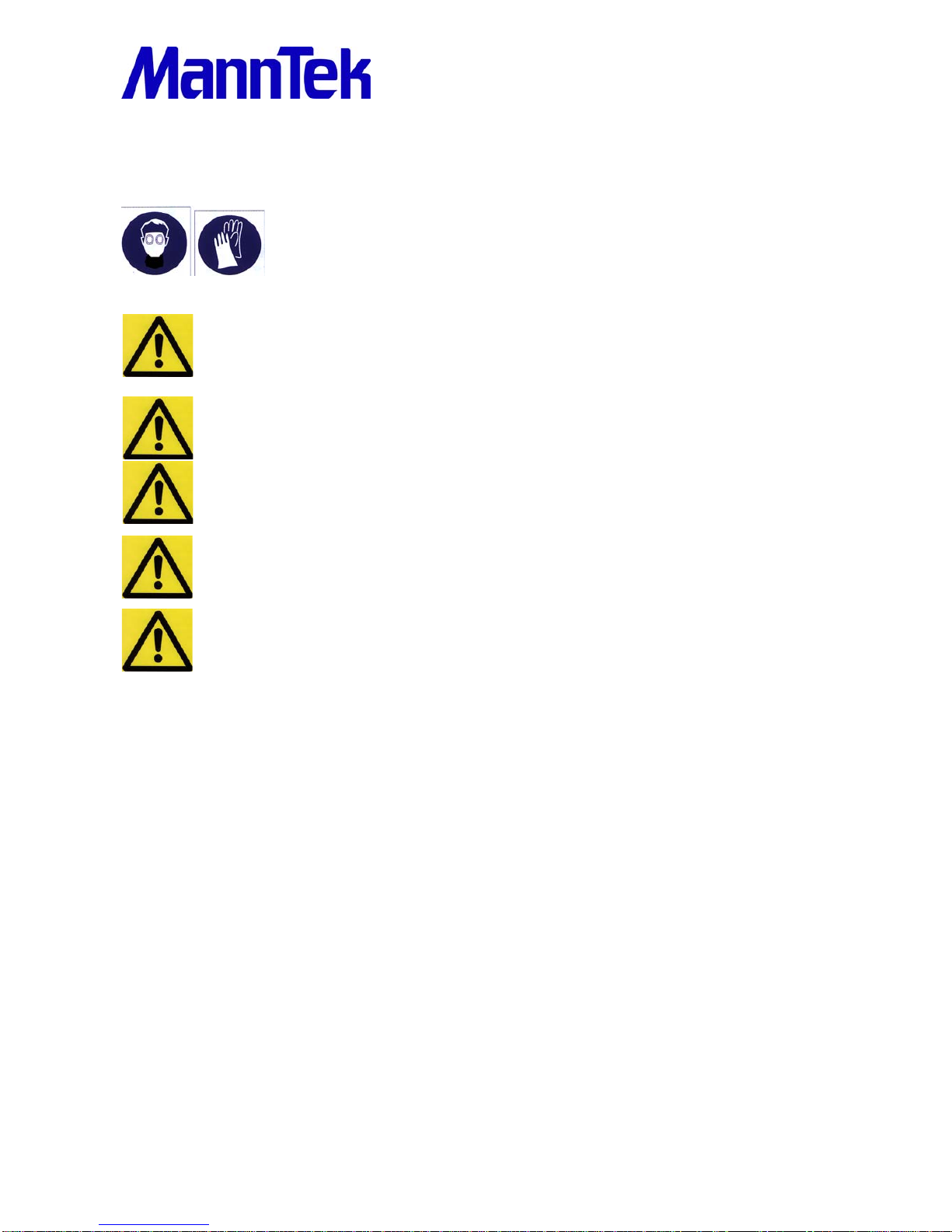
SAFETY INSTRUCTIONS
Wear proper safety clothing consists of thermal gloves, full face shield
approved for cryogenic use and solid shoes capable to withstand cryogenic
spill whenever operating Cryogenic Break-Away Couplings.
Make sure the operating space is clear to avoid accidental contact with others and the
coupling interface is clean and dry. Use dry air or nitrogen to blow out the coupling
interface.
Do not use the CBCoupling in any way, not described in the specification. The user is
responsible to comply with all applicable federal, state and local laws and regulations.
Do not operate the CBCoupling if there is any visible damage. Stop immediately if
leakage occurs.
Make sure that there is no trapped liquid or excessive pressure.
Authorized and qualified personnel must carry out all assembly and maintenance
operations as described in this operating manual.
3 TRANSPORT AND STORAGE
The product may only be transported or stored absolutely clean. Suitable protection must be used for both
openings to ensure no damage occurs to the surfaces/sealed areas. The storage location must guarantee
adequate protection from corrosion or extreme temperatures.
DELIVERY CHECK
Check for any transportation damage. If so report this immediately to the forwarder.
Check that the products and quantities are in accordance with the delivery note.
COMPLAINTS /RETURN OF GOODS
If returning goods please contact Mann Teknik AB to receive a Complaint Report form.
Complete the form with as much details as possible.
Return the goods with the Complaint Report attached on the outside of the package!
STORAGE
Store coupling in a dry, dust free, dark place, in ambient temperature.

Operating Manual
PR-101131-0121 Version 180905 9 of 16
4 INSTALLATION
INITIAL OPERATION
The correct installation of all MannTek products is essential to ensure safe and satisfactory operation.
Checks should be made to ensure that the fitting of MannTek products does not interfere with the correct
operation of affiliated equipment (i.e. isolation valve, excess flow valves, etc). Before securing the flange or
thread connections to mating equipment (i.e. hose, loading arm and storage tank) ensure that no foreign
objects, dirt, grit, water (moisture) etc. are present in the coupling.
All flange and thread connections should be made without imparting excessive strain to the equipment. All
gaskets and sealing materials used to make the permanent connection should be of suitable material.
Each MannTek product is designed to take reasonable axial loads associated with good handling practice
but is not designed to accept continuous excessive load values associated with maladjustment or poor
installation. Continuous excessive strain will equate to increased component wear and possibly premature
failure if not corrected.
When MannTek equipment is used with hoses, attention should be paid to hose length to ensure correct
handling characteristics. The hose assembly should be designed such that the minimum hose length is
supported by the coupling or the operator. Hoses should be of sufficient length to ensure operation well
within the stipulated hose minimum bend radius up to the maximum operation envelope.
INSTALLATION
When installing MannTek equipment to new pipe work, tanks, etc. ensure the system is free from debris that
may be transferred through the coupling. Where the hose or loading arm assembly is the primary static
dissipation or earth route, the electrical continuity value of the assembly shall be checked to ensure
regulatory compliance. Special attention should be paid to the balancing of loading arms. It is usual for
loading arm balance settings to account of weight variations due to differences in the full / empty cycle. The
loading arm should be set to balance in the condition present at the time of connection.
Before mounting the CBCouplings ensure that trapped liquid never can occur in the installation. In
combination with a Dry Cryogenic Coupling or Emergency Shut Down Valve measures shall be taken to
ensure that no liquid can be trapped in any operating mode.
Then the CBCoupling can be installed directly in the product line and is ready for use after removing the
transport protection.
Operating Manual
PR-101131-0121 Version 180905 10 of 16
The installation is as follows:
Remove the packaging.
Check the coupling for damages before mounting.
Ensure that the product line is empty and all valves are closed before you assemble the coupling
into the line.
To prevent damages during mounting a suitable wrench should be used for the intended nut flats
on the coupling (threaded connection) or the bolts (flanged connection).
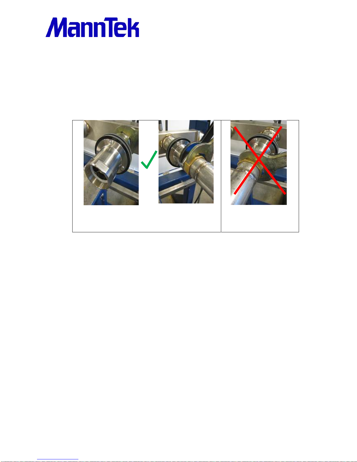
Usealwaysafittingwrenchtomountthecouplingtoahose,apipeor
atank.Tightenthefittingusingthewrenchontherespectiveside
wheretheconnectionismade.
Torqueforcesshouldneverbe
transferredviatheCBCouplingand
thebreakingpins.
The start-up may take place only when the CBCouplings has been mounted as instructed and the necessary
function tests and leak tests have been conducted by the approved authorities.
5 OPERATION
GENERAL NOTES
Operators are obliged to provide qualified and trained personnel familiar with the handling of supply pipes,
safety couplings, any fluid being pumped as well as its danger potential. Such staff must also be familiar with
the applicable safety regulations and the regulations of the employer’s liability association.
DAILY VISUAL INSPECTION
All couplings should be inspected at the start of each day’s operation. Check for leakage and any obvious
physical damage (such as impacts, etc.).
DISMANTLING
When the CBCoupling is taken out of service, the risk of liquid or gas spurting out should be taken into
consideration. Special protective measures such as personal protection equipment must therefore be
adopted.
Operating Manual
PR-101131-0121 Version 180905 11 of 16
How to dismantle:
a. Wear suitable personal safety equipment.
b. Make sure that the coupling is depressurized and empty.
c. Unscrew coupling always with a wrench fit for purpose.
IMPROPER USE
The equipment should never be used in the case of visible damage or where there is prior knowledge of
damage that may lead to malfunction.
6 MAINTENANCE AND REPAIR
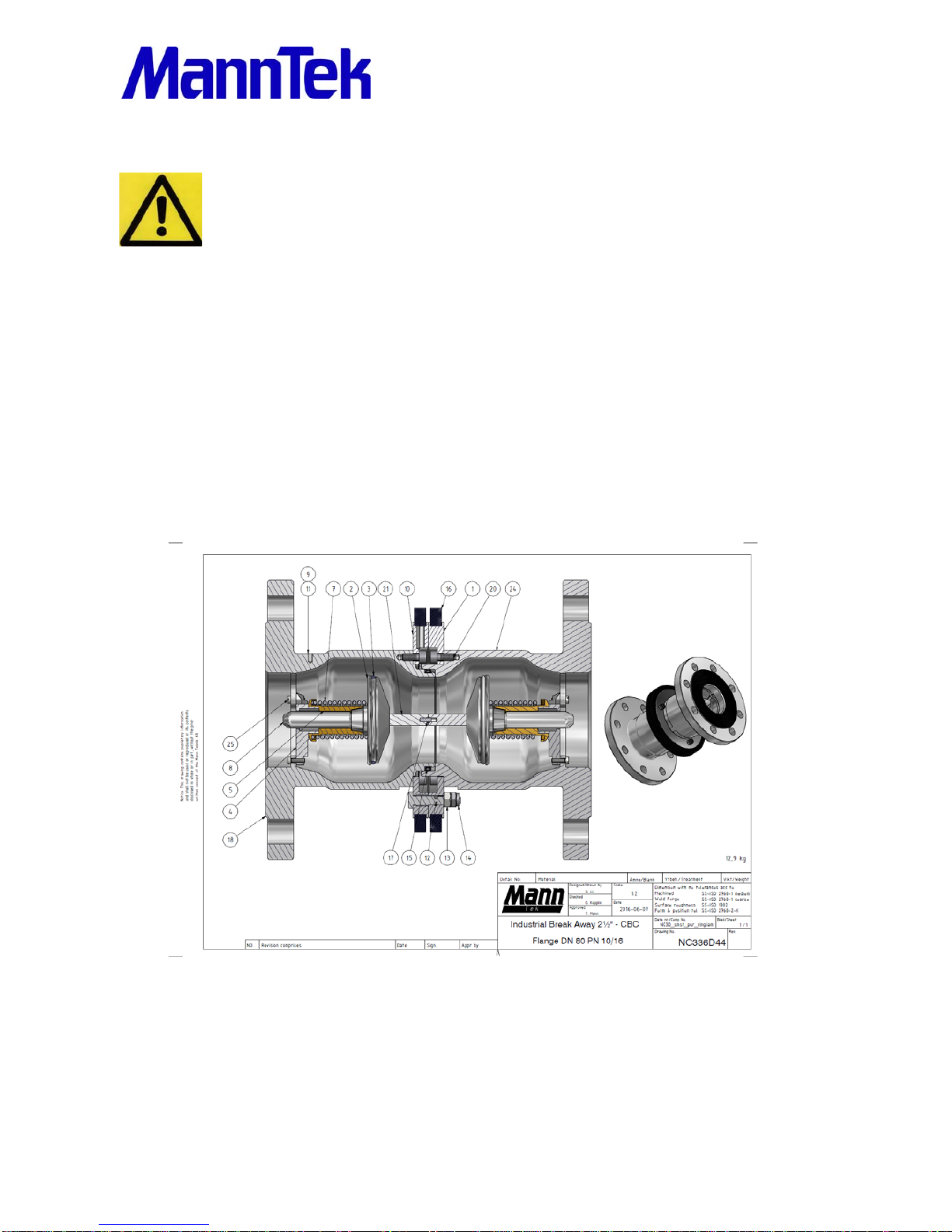
GENERAL INFORMATION
The CBCoupling consists of two housing halves with a check valve in each. The housings are held together
by three breaking bolts during normal operation. The two check valves support each other during normal
operation and keep the conduit open.
In case the supplying tank, e.g. a tank truck, moves from the filling area and someone forgot to disconnect
the supply line, the CBC is activated as follows:
Before the supply line is stressed by undue external forces the breaking pins will break. The CBC halves are
separated from each other and the spring-loaded check valves instantaneously close both ends of the line.
On the industrial version one half of the coupling remains firmly connected to the tank wagon while the other
half of the coupling remains connected to the supply line. The marine type is always placed between two

Operating Manual
PR-101131-0121 Version 180905 12 of 16
hoses. The pull force is only working in axial direction. After releasing both halves remain at the end of each
hose. This prevents the outflow of liquids or gases from both product carrying ends of the line.
Maintenance tasks, to put the released coupling back into service, may be performed only by
trained personnel from an authorised professional workshop. All measures necessary for
inspection, maintenance and repair must be carried out in accordance with the national
regulations of the country where the system is installed.
MAINTENANCE AND SERVICE INSTRUCTION
Always depressurise the system and rinse off the parts before beginning any maintenance
work. Use protective goggles. Do not handle O-ring seals if the material appears charred,
gummy or sticky.
Use tweezers; wear gloves and protective goggles in appropriate material, consult the material
safety data sheet (MSDS) of your product. Do not touch adjacent parts with unprotected
hands. Rinse off the parts once again before starting the “daily inspection”
SPARE PARTS AND TOOLS
Breaking-bolt-kit
3 Breaking bolts.
In case of failure or break away order the CBC-BOLT SET and carry
out repairs according to the assembly instructions.
Attention: Do not forget to specify the proper size and breaking force!
Please check with the information on the ID-plate and the head of the
bolt.
Outer body sealing ring
Operating Manual
PR-101131-0121 Version 180905 13 of 16
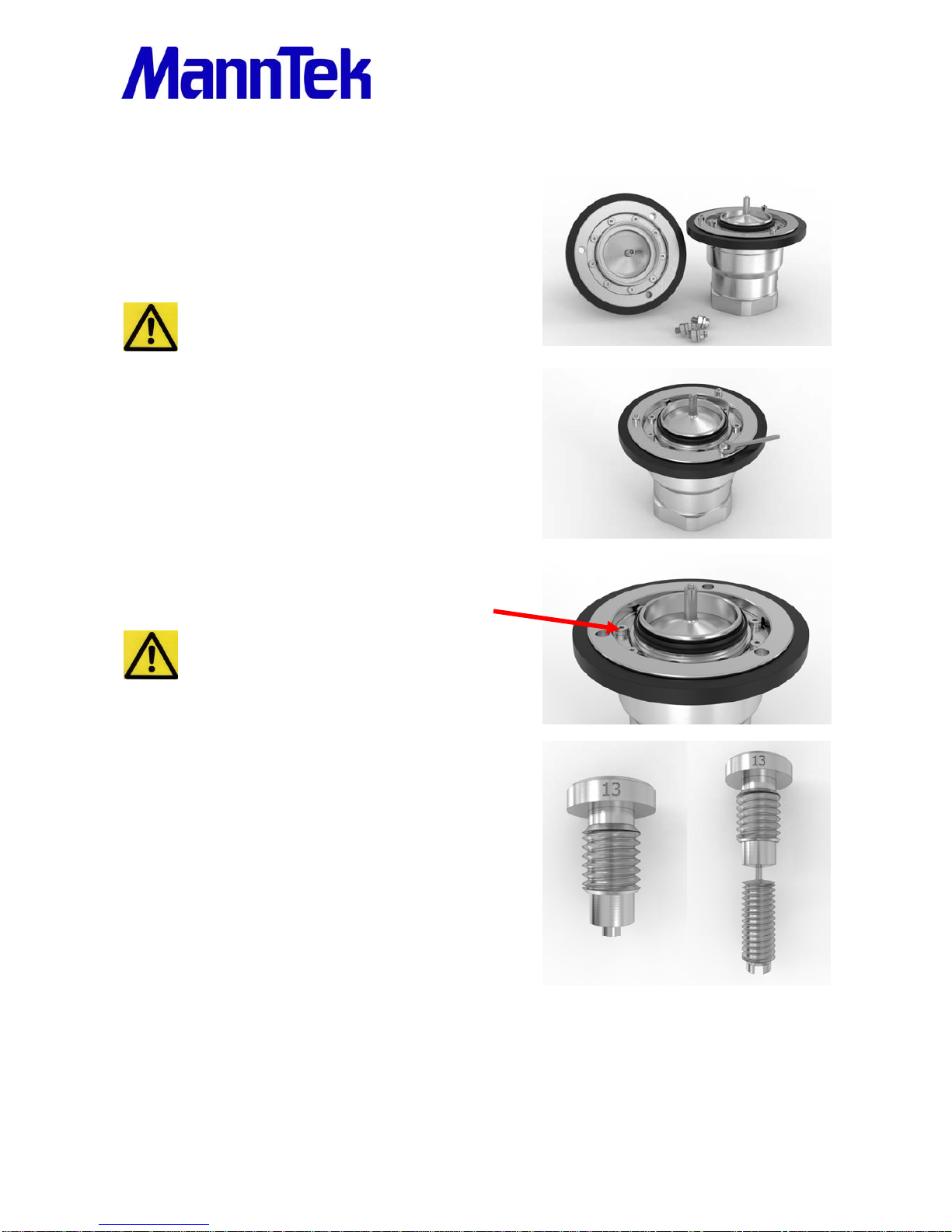
RESETTING AFTER RELEASE
DISMANTLING
When the coupling is taken out of service and dismantled
there is a danger that the fluid will spurt out. Special protective
measures such as personal protection equipment must
therefore be adopted.
a. Wear suitable personal safety equipment.
b. Make sure that the coupling is depressurized
and empty.
VISUAL INSPECTION
Screw out the destroyed parts of the breaking bolts.
Check for dirt, seal damage and any obvious physical damage
(such as impacts, etc.).
Tool: wrench size acc. to Table 6, bolt.
OUTER BODY SEALING RING
Replace the sealing ring on the body with a new one.
Make sure that the seal doesn’t get scratched when
mounting. The open profile should be in the
direction which is shown in the picture.
BREAKING BOLTS
Replace the bolts only by original spare parts from Mann Tek
with the same breaking force.
Example shows 13 kN breaking bolts
Operating Manual
PR-101131-0121 Version 180905 14 of 16
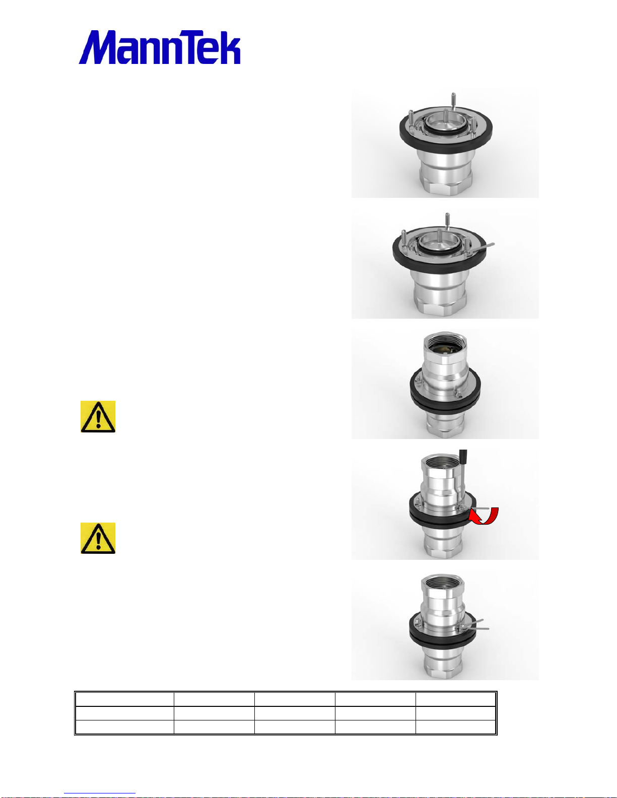
BREAKING BOLTS
Screw in the bolts into the intended position.
BREAKING BOLTS
If necessary tighten the bolt with a wrench.
Tool: Standard wrench size acc. to Table 6, bolt.
FIX BREAKING BOLTS
Screw on the nuts by hand until stop when halves are pressed
together.
Do not use force for tightening! Risk of destroying
bolts.
FIX BREAKING BOLTS
Fasten it a little bit with a wrench, max 45 degrees.
Tool: Standard wrench acc. to Table 6, nut.
It is important that all 3 bolts are mounted in the
same way. Risk that 1 bolt will be destroyed before
the others.
FIX BREAKING BOLTS
Screw on the second nut and lock the first one. Hold the
first one with a wrench to avoid forces on the breaking bolt.
After the coupling is completely reassembled provide a
pressure test according to test procedure on page 10.
Table 6: Standard Wrench size
StandardwrenchforDN25DN50/65/80DN100DN150
Nut8mm10mm13mm17mm
Bolt4mm6mm7mm9mm

Operating Manual
PR-101131-0121 Version 180905 15 of 16
PRESSURE AND TIGHTNESS TEST
After each service a pressure and tightness test of each coupling is mandatory. Test each half separately
before you connect both halves with the breaking pins. The following test parameters are in accordance with
EN12266 and ISO5208:
Shell tightness test: 1,5 x Working Pressure stop time 1 min.
Seat tightness test: 6 bar +/- 1bar stop time 15 s.
0,1 x Working Pressure stop time 15 s.
Instead of water we recommend to make the tightness test with gas, e.g. N2. If water is used as testing
media, after testing all water must be removed from the couplings to avoid freezing under low temperature
service.
If a pressure test should be achieved for the coupling mounted in an assembly follow the respective test
instructions for the equipment but do not exceed our recommended maximum test pressure of the coupling
which you will find in the following table. If testing with higher pressure is necessary please ask our sales
department for a special test bolt kit.
DN25DN50DN65DN80DN100DN125DN150
kNbarkNbarkNbarkNbarkNbarkNbarkNbar
4107101110181028104010
61610161516241637165416
72012201820282045206520
92515202325362556258125
4,825 9225
3161250203030354835754010840
3,2161337,52237,53337,55237,58137,511737,5
Table 8: Maximum Test Pressure depending on size and breaking force:

Operating Manual
PR-101131-0121 Version 180905 16 of 16
7 APPLICABLE DOCUMENTS
EU Guideline 2014/68/EU PED, 2014/34/EU ATEX
International Transport of Dangerous Goods ADR, RID, IMDG
Test standards EN12266, EN14432, ISO5208
Thread standards ISO 228, ANSI B1.20.1 - Flange standards EN 1092, ANSI B16.5
For use in other countries:
Respective national requirements and guidelines
7.1 DECLARATION OF CONFORMITY
2014/68/EU PED 2014/34/EU ATEX
© Copyright 2014 Mann Teknik AB. Mann Teknik AB reserves the right to make changes at any time in
prices, materials, specifications and models and to discontinue models without notice or obligations.
Mann Teknik AB
Strandvägen 16, S-54231 Mariestad, Sweden
Phone +46 501 393200 • Fax +46 501 393209
ISO9001-company.
Table of contents
Other Manntek Industrial Equipment manuals

Manntek
Manntek DCC Original operating manual

Manntek
Manntek DDC Original operating manual

Manntek
Manntek SBC User manual

Manntek
Manntek SBC Original operating manual

Manntek
Manntek DAC User manual

Manntek
Manntek PERC Original operating manual

Manntek
Manntek DCC Original operating manual

Manntek
Manntek SBC User manual

Manntek
Manntek DDC Original operating manual

Manntek
Manntek SBC Original operating manual


