manroland Roland 700 User manual

ROLAND 700
Option
ROLAND InlineInspector

Imprint
Type of document: Option
ROLAND InlineInspector
Product: ROLAND 700
Series: 778
Construction year: 2021
Target group: ●Owner-user of a printing shop
●Operating personnel (Helper ‒Skilled worker: printing machine operator)
Language: EN ‒English
Ref.no.: 80 95A EN H025
Publication status: 08.03.2021
Remarks concerning this manual The instructions of this manual correspond to the technical development of your print-
ing machine at the time of publication of the manual.
All rights reserved, subject to changes any time.
The original manual is written in German. All EC translations are based on the lan-
guage of the original manual.
manroland sheetfed GmbH
Mühlheimer Straße 341
63075 Offenbach am Main
Germany
© Copyright by manroland sheetfed GmbH 2021
All parts of this documentation are protected by copyright.
Any use outside the limits of the copyright is not allowed without the written consent of manroland. This applies, in particular, to the
publication, reproduction and translation of this documentation or parts of it as well as to the storage and processing of its contents
by electronic data processing systems.

22.02.2021 08:18:48 - 778 - 80 95A EN H025
Contents
ROLAND 700 ‒Option I
Contents
1 Specifications on the documentation . . . . . . . . . . . . . . . . . . . . . . . . . . . . . . . . . . . . 1
1.1 Documentation of your printing machine . . . . . . . . . . . . . . . . . . . . . . . . . . . . . . . . . . . . 1
1.2 Contentofthismanual ............................................... 1
1.2.1 Note for representation of parameters and screen masks . . . . . . . . . . . . . . . . . . . 1
1.2.2 Note on auxiliary equipment (aids, tools, testing and other devices) . . . . . . . . . . . . . 1
2 Safety ......................................................... 2
2.1 Safetynotes ..................................................... 2
2.2 Intendeduse ..................................................... 2
2.2.1 Instructions for the Safety chapter . . . . . . . . . . . . . . . . . . . . . . . . . . . . . . . . . . 2
2.2.2 Documentation ............................................. 3
3 Sheet inspection system - what is that? . . . . . . . . . . . . . . . . . . . . . . . . . . . . . . . . . . . 4
3.1 Description ...................................................... 4
4 Centralcontrolconsole ............................................. 5
4.1 Overviewofcomponents.............................................. 5
4.1.1 Central control console with switch cabinet of the sheet inspection system . . . . . . . . . 5
4.1.2 Hazardpoints .............................................. 6
4.1.3 Main switch of the sheet inspection system . . . . . . . . . . . . . . . . . . . . . . . . . . . . 6
4.1.4 Useofthemainswitch ......................................... 6
4.2 Software operation of the sheet inspection system . . . . . . . . . . . . . . . . . . . . . . . . . . . . . . 7
4.3 CreatePDF ...................................................... 7
4.4 Typicalfalsealarms ................................................. 7
5 Printingmodule .................................................. 8
5.1 Settingtheclockedblastair ............................................ 8
5.2 Elements of the sheet inspection system . . . . . . . . . . . . . . . . . . . . . . . . . . . . . . . . . . . . 8
5.3 Cardboardprinting ................................................. 9
5.4 Sheetguidingelement ............................................... 9
5.4.1 Removing the sheet guiding element . . . . . . . . . . . . . . . . . . . . . . . . . . . . . . . . 9
5.4.2 Removingthebaffleplate ...................................... 10
5.5 Cleaning the sheet inspection system . . . . . . . . . . . . . . . . . . . . . . . . . . . . . . . . . . . . . 11
5.5.1 CleaningtheLEDlamp ....................................... 11
5.5.2 Cleaning the outside of the glass pane of the camera housing . . . . . . . . . . . . . . . 12

22.02.2021 08:18:48 - 778 - 80 95A EN H025
Contents
II ROLAND 700 ‒Option
6 Delivery ....................................................... 13
6.1 Stripinsertingdevice ............................................... 13
6.1.1 Removing the strip inserting device . . . . . . . . . . . . . . . . . . . . . . . . . . . . . . . . 13
6.1.2 Installing the strip inserting device . . . . . . . . . . . . . . . . . . . . . . . . . . . . . . . . . 13
A Maintenanceschedule ............................................. 15
A.1 Work not dependent on operating hours (max. 20 000 s/h) . . . . . . . . . . . . . . . . . . . . . . . . 15
A.2 Work not dependent on operating hours (up to 18 200 s/h) . . . . . . . . . . . . . . . . . . . . . . . . 15

22.02.2021 08:18:48 - 778 - 80 95A EN H025
Specifications on the documentation
Documentation of your printing machine 1
ROLAND 700 ‒Option 1
1 Specifications on the documentation
1.1 Documentation of your printing machine
This manual is one part of the technical documentation for your printing press.
1.2 Content of this manual
The manual contains the information required for operating and maintaining this option.
manroland assumes that you read and understood the entire technical documentation that belongs to your
printing machine.
1.2.1 Note for representation of parameters and screen masks
Parameters and screen masks are used for illustration purposes.
Parameter
The values of the parameters represented in the manual (e.g. sheets per hour: 1,000 to 10,000 s/h) - in the text
and in screen masks - are used for illustration purposes. The parameters may deviate depending on the configura-
tion and combination of options of your printing machine.
Screes The screen masks represented in the manual are used for illustration purposes. The machine, components and
ancillary equipment shown may deviate from your printing machine.
1.2.2 Note on auxiliary equipment (aids, tools, testing and other de-
vices)
The aids, tools and testing and other devices described in chapter ’Equipment’ are required in order to
perform the tasks described in this manual correctly. However, not all of this auxiliary equipment is part of
the standard scope of delivery of your printing press. You can order individual items of auxiliary equipment
from manroland by quoting the reference numbers listed. Items of auxiliary equipment listed in this manual
without a reference number, are not part of the standard scope of delivery and cannot be ordered from
manroland. The optional auxiliary equipment available from manroland is indicated as follows in this
manual:
(*) Optional and not included in the standard scope of delivery
22.02.2021 08:18:48 - 778 - 80 95A EN H025
2
Safety
Safety notes
2ROLAND 700 ‒Option
2 Safety
2.1 Safety notes
Function of the warnings
Warnings warn of dangers when handling the product. According to the risk level (degree of danger), the
dangers are classified, designated, described and supplemented by notes to avoid them.
A warning placed at the beginning of a task signalizes that the risk prevails during the entire job.
A warning placed directly before an instruction signalizes that the risk relates to the next step to be taken.
Design of warnings
All warnings are designated by a signal word and a triangular warning symbol. The combination of signal
word and warning symbol determines the risk level (degree of danger).
Note
The warning symbol can be supported by pictographs showing the type of danger or how to avoid it in
order to focus the reader's attention.
DANGER
Designates an imminent danger that is certain to cause serious injury or death.
WARNING
designates an imminent danger that may cause serious injury or death.
CAUTION
designates a potentially dangerous situation that may cause minor injuries.
CAUTION
designates a possible situation during which the machine or an object in its vicinity may be damaged.
CAUTION
Designates a possible situation during which may cause environmental damage.
2.2 Intended use
2.2.1 Instructions for the Safety chapter
The manuals Operation and Maintenance of the printing machine contain detailed instructions for the safety
of the printing machine. These instructions logically also apply to the option described here.
●You must have read and understood chapter 1 Documentation of your printing machine and chapter 2
Safety in the Operation manual and in the Maintenance manual of the printing machine before starting
the tasks described in this manual.
●You must have read and understood the safety notices in the supplied documentation of the manufactur-
ers of the ancillary equipment before starting the tasks described in this manual. These manuals are part
of the technical documentation of your printing machine.

22.02.2021 08:18:48 - 778 - 80 95A EN H025
Safety
Intended use 2
ROLAND 700 ‒Option 3
2.2.2 Documentation
Operating manuals contain instructions for the safe, adequate and economical handling of your printing ma-
chine. Carry out all work exactly in accordance with the instructions of the operating manual to avoid dan-
gers, to reduce repair costs and down-times as well as to increase the reliability and service life of your print-
ing machine.
▶You must have read and understood all manuals belonging to the machine before you work on it.
▶You must have read and understood the documentation of the ancillary equipment manufacturers. These
manuals are part of the technical documentation of your printing machine.
22.02.2021 08:18:48 - 778 - 80 95A EN H025
3
Sheet inspection system - what is that?
Description
4ROLAND 700 ‒Option
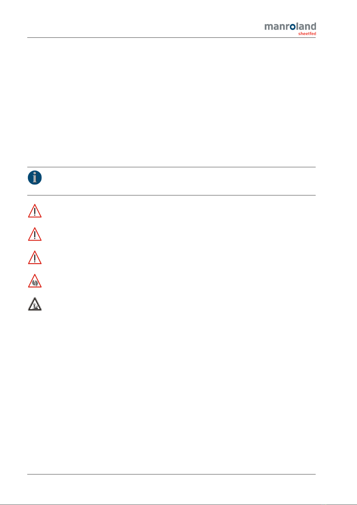
3 Sheet inspection system - what is that?
3.1 Description
LS-09841-1
During sheet travel, the sheet inspection system checks the printed sheet in the last printing module for pos-
sible faults. These errors could be dirt, scratches, creases, streaks in the printing material or fluctuations in
the printing process.
A camera (1) scans the freshly printed sheet (2) line by line on the impression cylinder (3). The recorded
data are compared in a computer with the reference sheet data. In the event of deviations, a warning signal
sounds and the detected errors are displayed and logged.
During inspection, the printer can analyze the detected faults on the screen (4). The printer can immediately
eliminate faults caused by the printing process.
In the delivery, faulty printed sheets are marked with a stripe.
It is possible to immediately eject the sheets using a sheet ejector (optional).
The sheets can be numbered consecutively (ROLAND InlineNumbering option). In the error log, the num-
bered sheets are assigned to the respective errors.

22.02.2021 08:18:48 - 778 - 80 95A EN H025
Central control console
Overview of components 4
ROLAND 700 ‒Option 5
4 Central control console
4.1 Overview of components
4.1.1 Central control console with switch cabinet of the sheet inspec-
tion system
LS-09842-1
1 Switch cabinet of the sheet inspection
system

22.02.2021 08:18:48 - 778 - 80 95A EN H025
4
Central control console
Overview of components
6ROLAND 700 ‒Option
4.1.2 Hazard points
CAUTION
Risk of damage by actuating the main switch. The installed software and the available data may be
damaged or deleted.
▶Only in an emergency is the operator allowed to actuate the main switch in order to cut off the
current of the sheet inspection system.
▶Only specially trained and authorized expert personnel from manroland or our sales/service part-
ner is allowed to actuate the main switch of the sheet inspection system.
CAUTION
Risk of distorted inspection results. The inspection system interprets foreign bodies in the inspec-
tion area as errors.
▶Prevent objects and body parts from entering the visual range of the camera.
4.1.3 Main switch of the sheet inspection system
K1169
Switching the sheet inspection system on or off in
dangerous situations.
Note
The main switch must always be in the posi-
tion ON.
4.1.4 Use of the main switch
Note
An actuation of the main switch causes the immediate standstill of the sheet inspection system without
a data backup. It does not affect the printing press.
Procedure
CAUTION
Risk of data loss. Risk of data loss when the main switch is actuated.
▶Actuate the main switch in an emergency only.

22.02.2021 08:18:48 - 778 - 80 95A EN H025
Central control console
Software operation of the sheet inspection system 4
ROLAND 700 ‒Option 7
K1169
▶In a dangerous situation, actuate the ’main
switch’ of the sheet inspection system.
◁The sheet inspection system will be switched
off.
◁Data that is not saved is lost.
4.2 Software operation of the sheet inspection system
Note
Information about operating the software is located in the instruction manual of the manufacturer.
4.3 Create PDF
Note
Follow the PDF specification and the checklist for creating a PDF –see Manufacturer's Operating
Instructions.
4.4 Typical false alarms
The following typical false alarms can occur by misinterpretation of the sheet inspection system.
Fault due to unsuitable reference sheet
If the sheet inspection system signals a larger number of faults at the start of the inspection, the cause often
is an unsuitable reference sheet. In this case you will have to read in a new reference sheet.
Note
For more information, see the manufacturer's operating manual.
Fault at the sheet tail edge
When printing cardboard starting from 130 N/mm, it is possible that the sheet tail edge lifts off from the im-
pression cylinder.
Redefine the area to be inspected to ignore the lift-off of the sheet tail edge.
Note
For more information, see the manufacturer's operating manual.
22.02.2021 08:18:48 - 778 - 80 95A EN H025
5
Printing module
Setting the clocked blast air
8ROLAND 700 ‒Option
5 Printing module
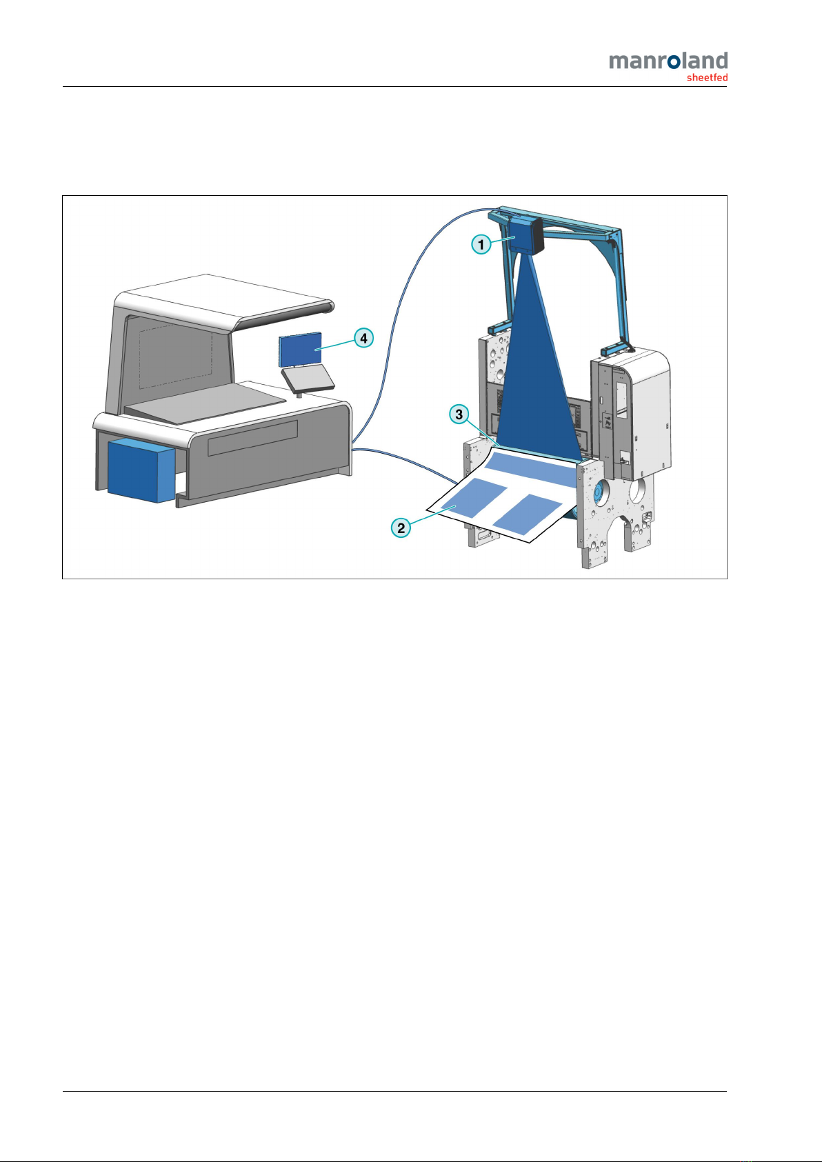
5.1 Setting the clocked blast air
Note
The blast air prevents the deflection of the sheet tail edge onto the baffle plate or the inspection lamp,
as well as the formation of corrugation with thin printing materials (<150 g/m²)
Procedure
05-09047-2
▶Set the blast air with rotary button (1).
Technical data
Turning to the left = more blast air
Turning to the right = less blast air
Turning to the right up to the stop = Blast air is switched
off
5.2 Elements of the sheet inspection system
05-09840-4
1 Sheet guiding element
2 Inspection lamp
3 Baffle plate with blast tube
22.02.2021 08:18:48 - 778 - 80 95A EN H025
Printing module
Cardboard printing 5
ROLAND 700 ‒Option 9
5.3 Cardboard printing
If necessary in cardboard printing, you can remove various elements to improve the printing result.
Elements to be removed Inspection restrictions ICP restrictions
●Baffle plate with blast tube ●for UV intermediate dryer
●for printing material <150 g/m² -/-
●Sheet guiding element
and
●Baffle plate with blast tube
●for UV intermediate dryer
●for printing material <150 g/m²
●for UV intermediate dryer
●for inspection
Note
The inspection lamp must be switched
off.
5.4 Sheet guiding element
5.4.1 Removing the sheet guiding element
DANGER
Risk of personal injuries. Risk of injuries if this work is performed by a single person.
▶Always perform this task together with a second person.
Note
If you want to wash the impression cylinder manually, it will be necessary to remove the sheet guiding
element.
Procedure
1. Lock the printing machine with the ’Stop-Safe’ key - see the manual Operation.
2. Open guard 9.8 over the impression cylinder.

22.02.2021 08:18:48 - 778 - 80 95A EN H025
5
Printing module
Sheet guiding element
10 ROLAND 700 ‒Option
05-09839-1
3. Fold the retaining frame (1) open.
Option: UV final drier
◁The inspection lamp and the baffle
plate can be seen.
05-09845-2
4. Pull the locking mechanism (1) (A+B-side) out-
ward in the direction of the arrow and swing it
down in the direction of the arrow.
5. Reach into the intended cutouts (2) and pull the
sheet guiding element (3) evenly and parallel
out of the machine.
Note
For installing the sheet guiding ele-
ments, proceed in the reverse order.
Final tasks
▶Close guard 9.8 over the impression cylinder.
5.4.2 Removing the baffle plate
Material
Socket wrench, width across flats 10
Note
If possible, carry out this task together with a second person.

22.02.2021 08:18:48 - 778 - 80 95A EN H025
Printing module
Cleaning the sheet inspection system 5
ROLAND 700 ‒Option 11
Procedure
1. Lock the printing machine with the ’Stop-Safe’ key - see the manual Operation.
05-07076-1
2. Open guard 9.8 over the impression cylinder.
05-08090-1
3. Turn the threaded spindle (1) (B-side) out up to
the stop.
Material
Socket wrench, width across flats 10
◁The UV-drier protective housing is
unlocked.
4. Take UV-dryer protective housing (2) in the
direction of the arrow out of the machine.
5.5 Cleaning the sheet inspection system
5.5.1 Cleaning the LED lamp
Material
Lintfree cloth
Preliminary operations
1. Lock the printing machine with the ’Stop-Safe’ key - see the manual Operation.
2. Open guard 9.8 over the impression cylinder.

22.02.2021 08:18:48 - 778 - 80 95A EN H025
5
Printing module
Cleaning the sheet inspection system
12 ROLAND 700 ‒Option
Procedure
▶Clean the LED lamp.
Material
Lintfree cloth
Note
If you determine that the output of the LED lamp decreases, contact our sales/service partner.
Final tasks
▶Close guard 9.8 over the impression cylinder.
5.5.2 Cleaning the outside of the glass pane of the camera housing
Material
Lintfree cloth
Procedure
▶Clean the outside of the glass pane of the camera housing.
Material
Lintfree cloth
22.02.2021 08:18:48 - 778 - 80 95A EN H025
Delivery
Strip inserting device 6
ROLAND 700 ‒Option 13
6 Delivery
6.1 Strip inserting device
6.1.1 Removing the strip inserting device
Preliminary operations
1. Lock the printing machine with the ’Stop-Safe’ key - see the manual Operation.
2. Open guard 40 in front of the sheet removal zone.
Procedure
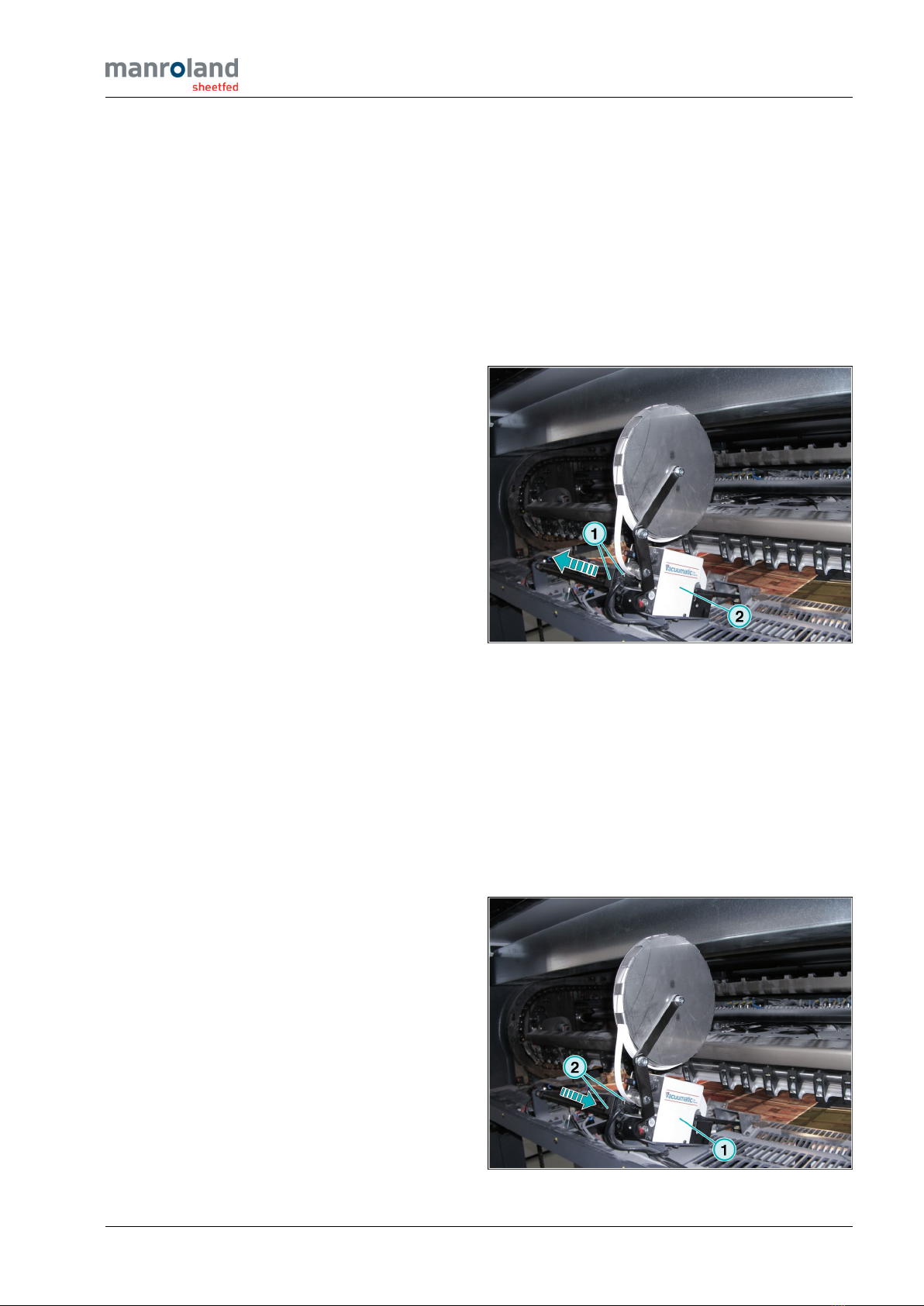
10-07722-2
1. Pull off both connectors (1) from the strip in-
serting device.
2. Carefully lift strip inserting device (2) in the
direction of the arrow out of the delivery.
Final tasks
▶Close guard 40 in front of the sheet removal zone.
6.1.2 Installing the strip inserting device
Preliminary operations
1. Lock the printing machine with the ’Stop-Safe’ key - see the manual Operation.
2. Open guard 40 in front of the sheet removal zone.
Procedure
10-07723-2
1. Carefully lift the strip inserting device (1) onto
the fixing plate at the delivery until it engages.
2. Connect the two connectors (2) to the strip
inserting device.

22.02.2021 08:18:48 - 778 - 80 95A EN H025
6
Delivery
Strip inserting device
14 ROLAND 700 ‒Option
Final tasks
▶Close guard 40 in front of the sheet removal zone.

22.02.2021 08:18:48 - 778 - 80 95A EN H025
Maintenance schedule
Work not dependent on operating hours (max. 20 000 s/h) A
ROLAND 700 ‒Option 15
Appendix
A Maintenance schedule
A.1 Work not dependent on operating hours (max. 20 000 s/h)
Interval Maintenance tasks Page
Once per week Cleaning the LED lamp 11
Once per month Cleaning the outside of the glass pane of the camera housing 12
A.2 Work not dependent on operating hours (up to 18 200 s/h)
Interval Maintenance tasks Page
Once per week Cleaning the LED lamp 11
Once per month Cleaning the outside of the glass pane of the camera housing 12

22.02.2021 08:18:48 - 778 - 80 95A EN H025
Index
16 ROLAND 700 ‒Option
Index
C
Cleaning
LEDlamp........................... 11
Clocked blast air
Setting .............................. 8
D
Description
Sheet inspection system . . . . . . . . . . . . . . . 4
E
Elements of the sheet inspection sys-
tem ................................... 8
F
False alarm
Sheetfrontedge...................... 7
Sheetrearedge ...................... 7
H
Hazard points
Mainswitch.......................... 6
I
Installation
Strip inserting device . . . . . . . . . . . . . . . . . 13
M
Main switch
Hazardpoints ........................ 6
Sheet inspection system . . . . . . . . . . . . . . . 6
Usage .............................. 6
R
Removal
Sheet guiding element . . . . . . . . . . . . . . . . . 9
Strip inserting device . . . . . . . . . . . . . . . . . 13
S
Setting
Clockedblastair...................... 8
Sheet front edge
Falsealarm.......................... 7
Sheet guiding element
Removal ............................ 9
Sheet inspection system
Description .......................... 4
Mainswitch.......................... 6
Sheet rear edge
Falsealarm.......................... 7
Strip inserting device
Installation.......................... 13
Removal ........................... 13
U
Usage
Mainswitch.......................... 6
Table of contents


